1
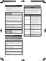
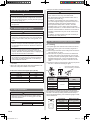
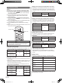
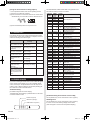
(3) Remote controller setting
1. Turn on all of the indoor units.
*1 Turn on the indoor unit with the unit number 0 last.
(Within 1 minute)
*2 When the indoor units are turned on, error codes
01 and 31 will be displayed; however, these error
codes will be deleted by setting the remote controller.
Therefore, continue with the setting procedure.
2. Set the refrigerant circuit address. (Assign the same
number to all of the indoor units connected to an
outdoor unit.)
Refrigerant circuit
address
Function Number
02
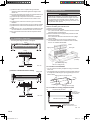
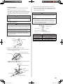
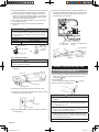
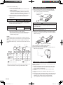
(1) Open up the knockout hole for the fresh-air intake, as
shown in the figure. (If using half-concealed installation,
open up the top knockout hole instead.)
For half concealed
installation
Indoor unit
Setting Value
00~15
3. Set the “master” and “slave” settings. (Set the indoor
unit that is connected to the outdoor unit using a transmission cable as the “master”.)
Function Number
Master
Slave
14. FRESH-AIR INTAKE
Setting Value
00
01
51
4. After completing the function settings, turn off all of the
indoor units, and then turn them back on.
* If error code 01, 1F, 30, 31, or 32 is displayed, there
may be an incorrect setting. Perform the remote
controller setting again.
CAUTION
• When removing the cabinet (iron plate), be careful not
to damage the indoor unit internal parts and surrounding
area (outer case).
• When processing the cabinet (iron plate), be careful not
to injure yourself with burrs, etc.
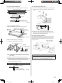
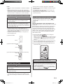
(2) Fasten the round flange (optional) to the fresh-air intake,
as shown in the figure. (If using half-concealed installation,
attach to the top.)
NOTE
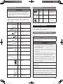
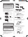
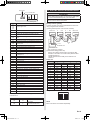
When different indoor unit models are connected using the
group control system, some functions may no longer be available.
If the group control system contains multiple units that are
operated simultaneously, connect and set the units as shown
below.
Round duct (option parts)
Standard Simultaneous
pair
twin
Simultaneous
triple
Outdoor
unit ①
Outdoor
unit ②
Indoor
unit
Indoor
unit
Indoor
unit
Indoor
unit
DIP switch setting
(Indoor unit)
0
1
2
3
4
5
Remote controller
setting
・
adress
00
01
01
02
02
02
00
00
01
00
01
01
Remote
controller
・Master/Slave
Outdoor
unit ③
[After completing “3. INSTALLATION WORK”...]
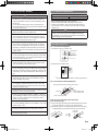
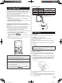
(3) Connect the duct to the round flange.
(4) Seal with a band and vinyl tape, etc. so that air does not
leak from the connection.
Indoor Indoor
unit
unit
: Transmission cable, Power supply cable
: Power supply cable
: Remote controller cable
: Bus wire
*Make sure that the indoor unit with the unit number 0 is connected to the outdoor unit using a transmission cable.
Duct
15. CUSTOMER GUIDANCE
Explain the following to the customer in accordance with the
operating manual:
(1) Starting and stopping method, operation switching, temperature adjustment, timer, air flow switching, and other
remote control unit operations.
(2) Air filter removal and cleaning, and how to use the air
louvers.
(3) Give the operating and Installation Manuals to the customer.
(4) If the signal code is changed, explain to the customer how
it changed (the system returns to signal code A when the
batteries in the remote control unit are replaced).
*(4) is applicable to using wireless remote control.
En-16
1125-9379122009.indd
16
2008/11/26
7:57:06