1
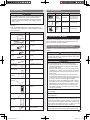
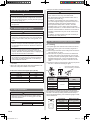
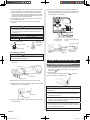
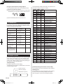
2.3. Accessories
2.4. Optional parts
Exterior
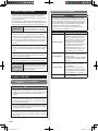
WARNING
• For installation purposes, be sure to use the parts supplied by the manufacturer or other prescribed parts.
The use of non-prescribed parts can cause serious accidents such as the unit falling, water leakage, electric
shock, or fire.
• The following installation parts are furnished. Use them as
required.
• Keep the Installation Manual in a safe place and do not
discard any other accessories until the installation work has
been completed.
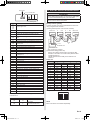
Name and Shape
Q’ty
Drain hose insulation
Coupler heat insulation
(Large)
Coupler heat insulation
(Small)
UTB-*UD
Round
duct
Drain
pump
unit
UTD-RF204
Unit control is performed by wired
remote controller
For Ceiling type
UTR-DPB241 For Ceiling type
3. INSTALLATION WORK
1
For fixing the drain hose
L : 280 mm
2
For indoor side pipe joint
(Gas pipe)
1
For indoor side pipe joint
(Liquid pipe)
4
For fixing the coupler heat
insulator
Binder
(Small)
4
For fixing the coupler heat
insulator
Special nut A
(Large flange)
4
Special nut B
(Small flange)
4
Installation
template
1
For installing indoor unit
For installing indoor unit
For positioning the indoor
unit
For connecting the piping
1
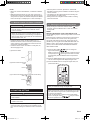
Remote control
unit
Use for air conditioner
operation
1
Battery (Penlight)
For remote control unit
Remote control
unit holder
Use as remote control unit
holder
1
2
Especially, the installation place is very important for the split
type air conditioner because it is very difficult to move from
place to place after the first installation.
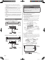
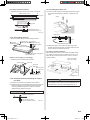
3.1. Selecting an installation location
Decide the mounting position together with the customer as
follows.
WARNING
• Select installation locations that can properly support the
weight of the indoor unit. Install the units securely so that
they do not topple or fall.
CAUTION
• Do not install the indoor unit in the following areas:
• Area with high salt content, such as at the seaside. It
will deteriorate metal parts, causing the parts to fall or
the unit to leak water.
• Area filled with mineral oil or containing a large amount
of splashed oil or steam, such as a kitchen. It will deteriorate plastic parts, causing the parts to fall or the unit
to leak water.
• Area that generates substances that adversely affect
the equipment, such as sulfuric gas, chlorine gas, acid,
or alkali. It will cause the copper pipes and brazed joints
to corrode, which can cause refrigerant leakage.
• Area that can cause combustible gas to leak, contains
suspended carbon fibers or flammable dust, or volatile
inflammables such as paint thinner or gasoline. If gas
leaks and settles around the unit, it can cause a fire.
• Area where animals may urinate on the unit or ammonia may be generated.
• Do not install where there is the danger of combustible
gas leakage.
2
Screw
(M3 × 12)
Wired
remote
controller
Summary
Description
Binder
(Large)
Auxiliary pipe
assembly
Model No.
Adhesive type 70 × 230
1
VT wire
Parts name
For remote control unit
holder installation
• Do not install the unit near a source of heat, steam, or
flammable gas.
• Install the indoor unit, outdoor unit, power supply cable,
transmission cable, and remote control cable at least 1 m
away from a television or radio receivers. The purpose of
this is to prevent TV reception interference or radio noise.
(Even if they are installed more than 1 m apart, you could
still receive noise under some signal conditions.)
• If children under 10 years old may approach the unit, take
preventive measures so that they cannot reach the unit.
En-3
1125-9379122009.indd
3
2008/11/26
7:57:04