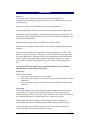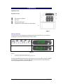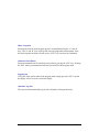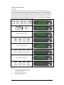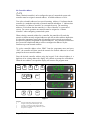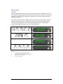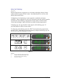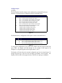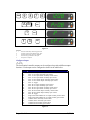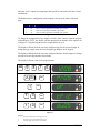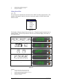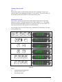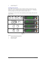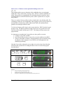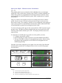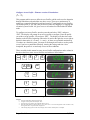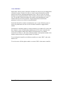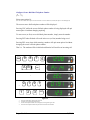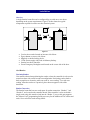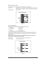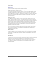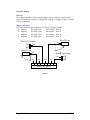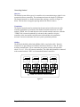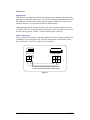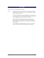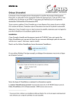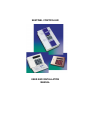
1
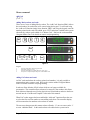
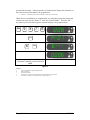
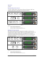
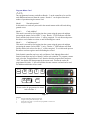
SENTINEL CONTROLLER
USER AND INSTALLATION
MANUAL
Input Connections.............................................. 30
Introduction ................................................3
Controller Outputs..........................................31
Overview..........................................................3
Overview ........................................................... 31
Output Connections........................................... 31
Interfacing ........................................................3
Networking.......................................................3
Programming................................................5
System access ............................................5
Keypad Overview ................................................ 5
Entering Passcode................................................ 5
Menu Navigation ................................................. 6
Command Cancellation ....................................... 6
Logging Out......................................................... 6
Automatic Log Out.............................................. 6
Menu commands ......................................7
Add Card.............................................................. 7
Adding Morley tokens and cards ................... 7
Adding PAC tokens and cards........................ 7
Delete Card .......................................................... 9
Removing Morley tokens and cards............... 9
Removing PAC tokens and cards................... 9
Program Master Card ........................................ 10
Change System Passcode .................................. 11
Set Controller Address ...................................... 12
Reset Controller................................................. 13
Select Card Technology .................................... 14
Configure Input.................................................. 15
Configure Output............................................... 16
Change System Time......................................... 18
Automatic Door Override.................................. 19
Setting a Door Override................................19
Cancelling a door Override ..........................20
Select Access - Firmware versions upto and
including version 2.25 ..................................21
Select Access Profile - Firmware versions
2.26 and above ..............................................22
Configure Access Profile - Firmware versions
up to and including 2.25 ...............................23
Configure Access Profile - Firmware versions
2.26 and above ..............................................24
Secure Dial-Back............................................... 25
Configure Secure Dial-Back Telephone
Number .........................................................26
Networking Sentinel.......................................32
Overview ........................................................... 32
Termination ....................................................... 32
Cabling............................................................... 32
Printer Port .....................................................33
Requirements..................................................... 33
Printer Connections ........................................... 33
Error Codes................................................ 34
Technical Support...................................... 35
Contacting Technical Support ........................35
Controller User Profile Template ............ 36
Card Record Template.............................. 37
Installation ..................................................27
Overview........................................................27
Card Readers...................................................... 27
Proximity Readers ............................................. 27
Reader Connection ............................................ 27
Morley Electronics Readers .........................28
PAC Proximity Readers ...............................28
Power Supply .................................................29
Requirements ..................................................... 29
Battery Backup .................................................. 29
Thermal Fuse ..................................................... 29
Overview............................................................ 30
Page 2 of 41
18/02/04
Introduction
Overview
The Sentinel 2 door controller range has been designed using the latest
microprocessor technology to provide an effective, easy to install and operate access
control package.
Sentinel can operate in both standalone and networked applications.
Sentinel supports up to 4,000 users in both stand-alone and networked applications.
Sentinel provides a comprehensive audit trail via the onboard serial printer port. The
audit trail is capable of holding 4,000 events, such as card addition and deletion, door
alarms and card transactions.
Both the transaction log and the card database are battery backed.
Sentinel provides a battery backed real time clock, which is displayed during normal
operation.
Sentinel accepts both Morley format and PAC format proximity card readers. The
Sentinel controller will accept a wide range of close, medium and long-range readers
for various applications, Sentinel will also accept combined proximity and biometric
readers, together with smart readers. Sentinel is also able to offer users a range of
token options, including ‘half clamshell’ cards, ISO cards for ID printing and key
fobs.
Note that PAC KeyPac readers are not included in this list. For any further
questions please contact Morley Electronics.
Interfacing
Each controller provides:
• Two ports for the connection of card readers.
• Four clean contact inputs for the connection of egress buttons and door contact
monitoring.
• Four relay outputs for the control of door release mechanisms and door alarm
indication.
Networking
The network capable version of the Sentinel controller supports connection of up to
16 controllers on a simple two-wire network, allowing a 32-reader system to be
created without the need for PC control. When networked, user cards can be added at
any controller and can be used immediately at any reader on the system.
When further controllers are added to an existing system the card database is
automatically synchronised, enabling simple no bother expansion of the system.
A fire alarm input is provided for connection to a fire alarm panel, allowing the
release of all doors on the system using only one input.
Page 3 of 41
18/02/04
Printer interface
A serial printer port is available to output log transactions. The data is formatted in
the PCL (level 5) printer language. This format is compatible with most commonly
available Inkjet and laser printers on the market today. For those users who have
parallel connection printers, Morley has a serial to parallel converter as an available
option; please contact Morley for further details.
All transactions are colour keyed to allow easy identification; however this does not
prevent the use of black & white printers, as coloured text will appear as black text.
Sentinel Enclosure Options
Sentinel controllers are available in optional housings.
Sentinel Wallmount controllers are housed in intruder keypads and require an external
power supply unit to power the controller.
Sentinel ruggedised controllers are housed in steel enclosures and have an on-board
power supply within the housing. There is also space for back-up batteries.
Sentinel Reader Options
Morley format readers are based on the HID range and Sentinel will accept any of the
readers in the HID range and combined proximity access and biometric fingerprint
readers. Sentinel also accepts smart card readers. For further details of the readers
available, please contact Morley Electronics Ltd.
Page 4 of 41
18/02/04
Programming
System access
Keypad Overview
Green Power indicator.
Not used.
Illuminated Keypad.
Flip down lid with Sentinel user instructions
Figure 1
Entering Passcode
To gain access to the Sentinel programming menu, press the ESC key and enter the
4-digit passcode, the default factory passcode is 9876.
ESC
9
8
7
6
1
2
Figure 2
Program
1.
2.
Press ESC followed by the four-digit passcode.
The display now shows the first option in the programming menu.
If at any point during passcode entry an incorrect key is pressed the escape key should
be used and the passcode re-entered. When the correct passcode is entered into the
system, the program menu will be displayed.
Page 5 of 41
18/02/04
Menu Navigation
Selecting the desired menu program option is accomplished using the ‘A’ and ‘B’
keys. The ‘A’ and ‘B’ keys scroll up and down the programme menu options. Once
the desired option has been selected, use the ‘ENT’ key to activate the command
Command Cancellation
Selected commands can be cancelled at any point by pressing the ‘ESC’ key. Pressing
the ‘ESC’ during a command will take the system back to the program menu.
Logging Out
To log out of the system when in the program menu simply press the ‘ESC’ key and
the display will revert to the clock time display.
Automatic Log Out
The system will automatically log out after 10 minutes of keypad inactivity.
Page 6 of 41
18/02/04
Menu commands
Add Card
[]
Adding Morley tokens and cards
There are two ways of adding Morley tokens. The ‘Add Card’ function (PR01) allows
the card number (on each token) to be entered using the keypad. To add cards using
the “Add card” function simply select function ‘PR01’ and using the keypad, enter the
number printed on the card to be added, press ‘ENT’ and token is added to the system.
Alternatively, tokens can be added via a ‘Master Card’. Refer to the section entitled
“Program Master Card” for details on master card programming.
ESC
9
8
7
6
1
ENT
2
3
3 0 5 7
ENT
Figure 3
Program
1.
2.
3.
4.
Press ESC followed by the four-digit passcode.
Select PR01, then press ‘ENT’
Enter the card number to be added, then press ‘ENT’ again
The process is complete. Repeat the process to add another token
Adding PAC tokens and cards
As PAC cards and tokens do not have printed card numbers, it is only possible to
program them using a master card. Refer to the section entitled “Program Master
Card” for details on master card programming.
In order to allow deletion of PAC tokens which are no longer available for
presentation. The controller allows tokens to be entered by slot number; this allows
their deletion without the need for the physical card. Slot numbers and user details are
entered into the ‘Card Record Template’ at the end of this manual.
When PAC reader support has been enabled the “Add card” function allows the user
to select the first card slot number to start adding cards from. The controller display
will increment the slot numbers as the tokens are added.
The user must then present their master tokens to Reader ‘1’* once to cause reader ‘1’
to enter ‘Addition Mode’. In this mode tokens to be added to the system can be
Page 7 of 41
18/02/04
presented to the reader. After presentation of each token the display will increment to
show the next card slot number to be programmed.
•
‘Reader 1’ is denoted on the Sentinel controller reader input connections.
When all new card additions are completed the user must then present the master card
a further two times to place Reader ‘1’ back into “Normal Mode”. Then the ‘ESC’
key must be pressed on the keypad to return the display to the program menu.
ESC
9
8
7
6
1
ENT
2
3
6
"""
ENT
4
Present master card to reader ‘1’ to select
“Add mode” and then present cards to be
added.
Figure 4
Program
1.
2.
3.
4.
5.
Press ESC followed by the four-digit passcode.
PR01 is displayed
Enter the slot number
The display now shows the slot number the next card presented will be placed at.
The process is complete. To add another token, repeat the process.
Page 8 of 41
18/02/04
Delete Card
[]
Removing Morley tokens and cards
To remove a Morley token or card select the “Delete card” function, “PR02” and
using the keypad enter the card number of the card to be removed.
9
ESC
8
7
6
1
2
3
A B
ENT
3 0 5 7
ENT
Figure 5
Program
1.
2.
3.
4.
Press ESC followed by the four-digit passcode.
Navigate to menu option PR02 then select it.
Enter the card number to be deleted, followed by ‘ENT’
The process is complete. To delete another token, repeat the process.
Removing PAC tokens and cards
PAC tokens can only be deleted by entering the slot number to which they were
allocated when first added to Sentinel. There are two deletion options; Pac tokens can
be deleted via the keypad by selecting ‘PR02’ and entering the PAC token slot
number into the keypad, followed by pressing the ‘ENT’ key, or via a Master Card.
For details on removing PAC tokens by Master Card, refer to the section entitled
“Program Master Card”.
9
ESC
8
7
6
1
2
A B
3
6
ENT
"""
ENT
Figure 6
Program
1.
2.
3.
4.
Press ESC followed by the four-digit passcode.
Navigate to menu option PR02 and press ‘ENT’.
Enter the slot number to be deleted and press ‘ENT’.
The process is complete. To delete further tokens, repeat the process.
Page 9 of 41
18/02/04
Program Master Card
[]
Once programmed a master card allows Reader ‘1’ on the controller to be used for
card addition and removal from the system. Reader ‘1’ can be placed into three
modes of operation using the master card.
Mode 1
“Normal operation”
In this mode user cards are processed in the normal manner with valid cards being
granted access.
Mode 2
“Card Addition”
This mode is entered by first logging into the system using the passcode and then
presenting the master card to reader ‘1’ once. Reader ‘1’ LED indicator will flash
slowly and the lock release for door ‘1’ will be energised. To exit this mode present
the master card a further two times or until all flashing has ceased.
Mode 3
“Card Removal”
This mode is entered by first logging into the system using the passcode and then
presenting the master card to reader ‘1’ twice. Reader ‘1’ LED indicator will flash
quickly and the lock release for door ‘1’ will be energised. To exit this mode present
the master card once again or until all flashing has ceased.
Each Sentinel controller may have only one Master Card, although Networked
Sentinel controllers may have a Master Card for each controller. To program a master
card, select the “Program Master Card” function from the program menu and press
‘ENT’, the display will then prompt for the master card. Present the card to be
programmed to reader ‘1’; the card will then become a master card and can be used
for addition and deletion of user cards.
9
ESC
8
7
6
1
2
A B
ENT
Present card to be programmed as master
card to Reader ‘1’
Figure 7
Program
1.
2.
3.
4.
Press ESC followed by the four-digit passcode.
Navigate to menu option PR03 and press ‘ENT’
Present the card to reader ‘1’, the card is then programmed as a master card
The process is complete.
Page 10 of 41
18/02/04
Change System Passcode
[]
To change the system passcode select “PR04” function from the program menu and press
‘ENT’. The display will then prompt for the current passcode. Enter the current four-digit
passcode, the display will then prompt for the new passcode. Entry of your new passcode
must be carried out twice for verification purposes. Only when the current passcode and new
passcode have been entered correctly and verified will your new passcode become valid.
From this point on the new passcode must be used to gain access to the system, although the
default passcode will be shown in further examples.
9
ESC
8
7
6
1
A B
2
ENT
Enter current passcode
9
8
7
6
""""
3
Enter new passcode
?
?
?
?
""""
4
Re-enter new passcode
?
?
?
?
""""
5
Figure 8
Program
1.
2.
3.
4.
5.
6.
Press ESC followed by the four-digit passcode.
Navigate to menu option PR04 and press ‘ENT’
Enter the four-digit passcode.
Enter the new four-digit passcode.
Re-enter the new four-digit passcode.
The process is complete.
Page 11 of 41
18/02/04
Set Controller Address
[]
When a Sentinel controller is to be configured as part of a networked system each
controller must be assigned a network address. Available addresses are 0-16.
Two of the selectable addresses have special meaning. Address ‘0’ indicates that the
controller is a standalone unit with no network attached and address ‘1’ indicates that
the controller is a “Master Controller” in a networked system. The remaining
addresses 2-16 indicate that the controller is a “Slave controller” in a networked
system. For correct operation one controller must be assigned as a “Master
controller” when configuring a networked system.
When selecting a network address for a controller, the controller will search the
network to obtain currently assigned addresses and will not allow address duplication.
It is therefore important to ensure that all controllers on the network are connected
and powered up before assignment of network addresses. Any controller connected to
the system with a duplicated address will be reconfigured to address 0 by the
firmware to prevent network conflicts.
To set the controller address select ‘PR05’ from the programme menu and press
‘ENT’, the controller will then search the network for network addresses in use and
prompt for the new controller address.
Enter the desired controller address using the keypad, if the selected address is a
duplicate of an existing address the display will continue to prompt for valid address.
When the new address is accepted the display will return to the program menu.
9
ESC
8
7
6
1
2
A B
ENT
3
4
0
1
ENT
Figure 9
Program
1.
2.
3.
4.
5.
Press ESC followed by the four-digit passcode.
Navigate to menu option PR05 and press ‘ENT’
Controller is searching for used network addresses.
Enter address for controller being added to the system.
The process is complete.
Page 12 of 41
18/02/04
Reset Controller
[]
The reset controller function allows the user to clear down the card database and reset
the controller configuration back to its factory default, once this function is carried out
data retrieval is not possible and for this reason the user must enter their passcode to
initiate this function.
To initiate this function select ‘PR06’ from the program menu. The display will then
prompt for the system passcode. Enter the current system passcode on the keypad.
Once the passcode has been verified the system database will be cleared and the
controller configuration will be reset to it’s factory defaults.
9
ESC
8
7
6
1
2
A B
ENT
3
9
8
7
6
""""
4
Figure 10
Program
1.
2.
3.
4.
5.
Press ESC followed by the four-digit passcode.
Navigate to menu option PR06 and press ‘ENT’.
Requesting the user to re-enter the four-digit passcode.
Re-enter the four-digit passcode.
The process is complete
Page 13 of 41
18/02/04
Select Card Technology
[]
Sentinel controllers have support for two card reader technologies: Morley format
readers and direct support for PAC readers. By default Sentinel is set for use with
Morley format card readers.
Configuration of card technology is only supported on standalone and master
controllers. When configured as a slave on a networked system the sentinel controller
will obtain the card technology configuration from the master controller and the
“Select card technology” option will not be accessible from the program menu.
Technology type ‘00’ provides PAC reader support, with technology type ‘01’
providing support for Morley format readers.
To change the card technology select the “PR07” function from the program menu
and press ‘ENT’, the display will show the currently configured technology type; the
user can now enter the technology to be used.
9
ESC
8
7
6
1
2
3
A B
ENT
0
ENT
0
Figure 11
Program
1.
2.
3.
4.
Press ESC followed by the four-digit passcode.
Navigate to menu option PR07 and press ‘ENT’.
Enter the required card reader technology.
The process is complete.
Page 14 of 41
18/02/04
Configure Input
[ ]
The four Sentinel controller inputs can be configured to perform different input
functions. Each input can be configured as shown in the table below.
Type
11
12
13
14
21
22
23
24
30
32
33
34
35
Function
Door ‘A’ Egress button normally closed contact.
Door ‘A’ Egress button normally open contact.
Door ‘A’ Door Monitor input normally closed contact.
Door ‘A’ Door Monitor input normally open contact.
Door ‘B’ Egress button normally closed contact.
Door ‘B’ Egress button normally open contact.
Door ‘B’ Door Monitor input normally closed contact.
Door ‘B’ Door Monitor input normally open contact.
Global Fire input normally closed contact.
Common Alarm. Normally closed contact.
Common Alarm. Normally open contact.
Common Fault. Normally closed contact.
Common Fault. Normally open contact.
Figure 12
The Default factory configuration of the inputs is shown in the table below.
Input
1
2
3
4
Type
12
13
22
23
Function
Door ‘A’ Egress button normally open contact.
Door ‘A’ Door Monitor input normally closed contact.
Door ‘B’ Egress button normally open contact.
Door ‘B’ Door Monitor input normally closed contact.
Figure 13
To change the configuration of any input select ‘PR08’ from the program menu and
press ‘ENT’, the display will then prompt for the number of the input to be
configured. Using the keypad enter the input number (1 to 4).
The display will then show the currently configured type for the selected input. To
change the input type, enter the new two-digit type number on the keypad. The
display will then return to the program menu, with the new input type configured.
Page 15 of 41
18/02/04
9
ESC
8
7
6
1
2
A B
3
4
1
ENT
"
ENT
1
3
ENT
Figure 14
Program
1.
2.
3.
4.
5.
Press ESC followed by the four-digit passcode.
Navigate to menu option PR08 and press ‘ENT’
Enter the number of the input to be modified.
Enter the new type number for this input.
The process is complete.
Configure Output
[!]
The four Sentinel controller outputs can be configured to perform different output
functions. Each output can be configured as shown in the table below.
Type
11
12
13
14
15
16
17
21
22
23
24
25
26
27
30
31
32
33
34
35
Function
Door ‘A’ Go output. Normally closed contact.
Door ‘A’ Go output. Normally open contact.
Door ‘A’ Door open alarm. Normally closed contact.
Door ‘A’ Door open alarm. Normally open contact.
Door ‘A’ Door alarm output. Normally closed contact.
Door ‘A’ Door alarm output. Normally open contact.
Door ‘A’ Toggle.
Door ‘B’ Go output. Normally closed contact.
Door ‘B’ Go output. Normally open contact.
Door ‘B’ Door open alarm. Normally closed contact.
Door ‘B’ Door open alarm. Normally open contact.
Door ‘B’ Door alarm output. Normally closed contact.
Door ‘B’ Door alarm output normally open contact.
Door ‘B’ Toggle.
Single Door Read in/Read out. Go output normally closed contact.
Single Door Read in/Read out. Go output normally open contact.
Common Alarm. Normally closed contact.
Common Alarm. Normally open contact.
Common Fault. Normally closed contact.
Common Fault. Normally open contact.
Figure 15
Page 16 of 41
18/02/04
Note that ‘Lock’ outputs are output types that would be connected to the door release
mechanisms.
The Default factory configuration of the outputs is shown in the table on the next
page.
Output
1
2
3
4
Type
12
14
22
24
Function
Door ‘A’ Lock output. Normally open contact.
Door ‘A’ Door open alarm. Normally open contact.
Door ‘B’ Lock output. Normally open contact.
Door ‘B’ Door open alarm. Normally open contact.
Figure 16
To change the configuration of any output select the ‘Pr09’ function from the program
menu and press ‘ENT’, the display will then prompt for the number of the output to be
configured. Using the keypad enter the output number (1 to 4).
The display will then show the currently configured type for the selected output, to
change the type simply enter the new two digit type number on the keypad.
The display will then show the currently configured duration for this output; to change
enter the new two-digit duration (in seconds).
The display will then return to the program menu.
9
ESC
8
7
6
1
2
A B
3
4
5
1
!
ENT
"
ENT
1
3
ENT
1
0
ENT
Figure 17
Program
1.
2.
3.
Press ESC followed by the four-digit passcode.
Navigate to menu option PR09 and press ‘ENT’.
Enter the number of the output to be modified.
Page 17 of 41
18/02/04
4.
5.
6.
Enter the new type number for this output.
Enter the new duration for this output.
The process is complete.
Change System Time
[]
To set the current controller day and time select ‘PR10’ from the program menu. The
display will prompt for the day, enter the current day number as shown in the table
below/overleaf.
Day
1
2
3
4
5
6
7
Function
Sunday
Monday
Tuesday
Wednesday
Thursday
Friday
Saturday
Figure 18
The display will then prompt for the current time. Using the keypad, enter the time in
24-hour format. The new day and time will now be set and the display will return to
the program menu.
9
ESC
8
7
6
1
2
A B
3
4
ENT
1
"
ENT
1 3 5 6
""""
5
Figure 19
Program
1.
2.
3.
4.
5.
6.
Press ESC followed by the four-digit passcode.
Navigate to menu option PR10 and press ‘ENT’.
Enter the current day number from the day table above.
Enter the current time (24 hour format).
Display now shows the current time.
The process is complete.
Page 18 of 41
18/02/04
Automatic Door Override
[]
The automatic door override function allows the user to program free access on a
reader for either 5 days (Monday to Friday) or 7 days a week. The system allows for
one override period to be defined for each reader on the system.
Setting a Door Override
Select “PR11” from the program menu and the display will prompt for the reader
number to override. Using the keypad enter the reader number 1 or 2. The display
will now prompt for the number of days to override the reader for, enter either 5 or 7.
Then enter the start time and end times (in 24-hour format).
Once configured the override will take effect immediately and the display will return
to the program menu.
9
ESC
8
7
6
1
2
A B
3
4
5
6
ENT
1
ENT
"
5
ENT
"
1 3 0 0
1 7 0 0
Figure 20
Program
1.
2.
3.
4.
5.
Press ESC followed by the four-digit passcode.
Navigate menu option PR11 and press ‘ENT’.
Select reader 1 (or 2) for override.
Enter 5 for five-day override.
Enter start time for override.
Page 19 of 41
18/02/04
6.
7.
Enter finish time for override.
The process is complete.
Cancelling a door Override
Select ‘PR11’ from the program menu, the display will then prompt for the reader
number to override. Using the keypad, enter the reader number 1 or 2. The display
will now prompt for the next step to override the reader, enter ‘0’.
Cancelling the override will take effect immediately and the display will return to the
program menu.
9
ESC
8
7
6
1
2
A B
3
4
ENT
1
ENT
"
0
ENT
"
Figure 21
Program
1.
2.
3.
4.
5.
Press ESC followed by the four-digit passcode.
Navigate to menu option PR11 and press ‘ENT’
Select reader 1 for override.
Enter 0 to cancel override.
The process is complete.
Page 20 of 41
18/02/04
Select Access - Firmware versions upto and including version 2.25
[]
This program enables users to determine which cardholders have access through
which doors. This is achieved by selecting a door ‘Profile’ to which cardholders are
added. Door profiles are programmable for stand alone Sentinel controllers and as
common profiles in networked Sentinel systems. (PR13 explains how to set up the
door profiles).
There are a total of 10 door profiles, the first of which (00) is the default profile. The
remaining 9 profiles are user configurable. After logging in to the system, profile 00 is
automatically selected and any tokens added in this mode will automatically be
granted access through each door reader.
To select an alternate profile, log in to the system and select ‘PR12’ from the keypad
and press enter. The display will then prompt for the new access profile to be used.
Enter the profile number and then press ‘ENT’. The display will then return to the
program menu.
It is important to remember that if you wish to use door profiles you must;
1. Configure your profile via PR13
2. Select the profile you wish to activate for your token additions from PR12
3. Then go to the PR01 or Master Card programming sequence without exiting
the program, thus keeping the Access Profile active throughout the card
addition programming.
Note that if you wish to change the access rights of an active token, first delete that
token from the system before re-adding the token via the Access Profile program
described above.
9
ESC
8
7
6
1
2
A B
3
1
ENT
"
ENT
Figure 22
Program
1.
2.
3.
4.
Press ESC followed by the four-digit passcode.
Navigate to menu option PR12 and press ‘ENT’
Enter the new access profile to be used and press ‘ENT’
The process is complete and you are ready to add tokens with this profile active.
Page 21 of 41
18/02/04
Select Access Profile - Firmware versions 2.26 and above
[]
This program enables users to determine which cardholders have access through
which doors. This is achieved by selecting a door ‘Profile’ to which cardholders are
added. Door profiles are programmable for stand alone Sentinel controllers and as
common profiles in networked Sentinel systems. (PR13 explains how to set up the
door profiles).
There are a total of 9 door profiles, the first two of which (00 and 01) are default
profiles. 00 gives access to all doors on the system and 01 gives no access to any
doors on the system. The remaining 7 profiles are user configurable. After logging in
to the system, profile 00 is automatically selected and any tokens added in this mode
will automatically be granted access through each door reader.
To select an alternate profile, log in to the system and select ‘PR12’ from the keypad
and press enter. The display will then prompt for the new access profile to be used.
Enter the profile number and then press ‘ENT’. The display will then return to the
program menu.
It is important to remember that if you wish to use door profiles you must;
1. Configure your profile via PR13.
2. Select the profile you wish to activate for your token additions from PR12.
3. Then go to the PR01 or Master Card programming sequence without exiting
the program, thus keeping the Access Profile active throughout the card
addition programming.
Note that if you wish to change the access rights of an active token, first delete that
token from the system before re-adding the token via the Access Profile program
described above.
9
ESC
8
7
6
1
2
A B
3
1
ENT
"
ENT
Figure 23
Program
1.
2.
3.
4.
Press ESC followed by the four-digit passcode.
Navigate to menu option PR12 and press ‘ENT’
Enter the new access profile to be used and press ‘ENT’
The process is complete and you are ready to add tokens with this profile active.
Page 22 of 41
18/02/04
Configure Access Profile - Firmware versions up to and including 2.25
[]
This program enables users to define Access Profiles, which can be used to determine
through which doors token holders may have access. There are a maximum of 32
readers on a networked Sentinel system and a total of 9 configurable Access Profiles.
The default profile is ‘00’ and is the profile used when first logging or re-logging into
a Sentinel system. Profile ‘00’ gives access to all readers for tokens added in default
mode.
To configure an Access Profile, enter the passcode and select ‘PR13’ and press
‘ENT’. The display will prompt for an access profile to configure. Enter the profile
you wish to set up (profiles 1-9) and press ‘ENT’. The display will show the reader
number on the left side (beginning with reader 01) and on the right, the access right or
denial for that reader (0 = no entry, 1 = entry). As there are a potential maximum of
32 readers on a Sentinel system, you must scroll through each reader to set the profile
(even if you have a stand alone Sentinel), entering the setting each time. Once
completed, the profile is set and ready for use in token additions.
There are tables in this manual to enter Access Profile configurations and a column in
the token data list to enter Access Profiles used with user issued tokens.
9
ESC
8
7
6
1
2
A B
3
ENT
1
ENT
"
1
ENT
"
1
ENT
"
Figure 24
Program
1.
2.
3.
4.
5.
Press ESC followed by the four-digit passcode.
Navigate to menu option PR13 and press ‘ENT’
Enter the new access profile to be configured and press ‘ENT’
With the reader number on the left, select ‘0’ for no access and ‘1’ for access through each of the 32 readers in turn,
entering each time to accept the reader configuration.
After entering the program for reader 32, the display returns to PR13 and the process is complete.
Page 23 of 41
18/02/04
Configure Access Profile - Firmware versions 2.26 and above
[]
This program enables users to define Access Profiles, which can be used to determine
through which doors token holders may have access. There are a maximum of 32
readers on a networked Sentinel system and a total of 7 configurable Access Profiles.
The default profile is ‘00’ and is the profile used when first logging or re-logging into
a Sentinel system. Profile ‘00’ gives access to all readers for tokens added in default
mode.
To configure an Access Profile, enter the passcode and select ‘PR13’ and press
‘ENT’. The display will prompt for an access profile to configure. Enter the profile
you wish to set up (profiles 2-8) and press ‘ENT’. The display will show the reader
number on the left side (beginning with reader 01) and on the right, the access right or
denial for that reader (0 = no entry, 1 = entry). As there are a potential maximum of
32 readers on a Sentinel system, you must scroll through each reader to set the profile
(even if you have a stand alone Sentinel), entering the setting each time. Once
completed, the profile is set and ready for use in token additions.
There are tables in this manual to enter Access Profile configurations and a column in
the token data list to enter Access Profiles used with user issued tokens.
9
ESC
8
7
6
1
2
A B
3
ENT
"
1
ENT
1
ENT
"
1
ENT
"
Figure 25
Program
1.
2.
3.
4.
5.
Press ESC followed by the four-digit passcode.
Navigate to menu option PR13 and press ‘ENT’
Enter the new access profile to be configured and press ‘ENT’
With the reader number on the left, select ‘0’ for no access and ‘1’ for access through each of the 32 readers in turn,
entering each time to accept the reader configuration.
After entering the program for reader 32, the display returns to PR13 and the process is complete.
Page 24 of 41
18/02/04
Secure Dial-Back
Sentinel has a facility for the connection of modems for remote access & management
of Sentinel systems. Sentinel Lite software controls modem functionality and this
software must be the controlling/management source. However, there are control
functions to be programmed into the remote Sentinel network which is to be dialled
into. This includes setting the telephone line number and establishing the secure
modem link between the two locations. Programming Sentinel with modem
parameters is achieved via ‘PR14’ as described below.
Sentinel & Sentinel Lite modem communications uses a secure dial back system to
ensure only authorised users have access to Sentinel controllers equipped with a
modem.
The Sentinel to which the modem is connected must be set as address 01 (master) and
there must be a secure call back phone number entered. If 0 (zero) is entered as the
secure call back phone number then Sentinel will assume there is no modem
connected even if there is. The secure call back number is the telephone number of the
modem connected to the PC running Sentinel Lite software.
To set the Sentinel controller as the Master controller, use menu ‘PR05’, and set the
address to 01
To set the secure call back phone number, use menu ‘PR14’ at the master controller.
Page 25 of 41
18/02/04
Configure Secure Dial-Back Telephone Number
[]
Select menu option 14.
(You will not be able to select option 14 if the controller is not set as address 01 (master) but option 14 will be displayed)
The current secure dial back phone number will be displayed .
Pressing ESC whilst the secure dial back phone number is being displayed will quit
menu option 14 without changing anything.
To enter a new (or first) secure dial back phone number, simply enter the number.
Pressing ENT when finished will result in the new (or first) number being saved.
Pressing ESC at any time whilst entering a number will quit menu option 14 without
changing the secure call back phone number.
That’s it. The modem will be initialised and Sentinel will wait for an incoming call.
9
ESC
8
7
6
1
2
A B
ENT
3
0
1
9 1
2
3
!
4
1
ENT
Figure 26
1.
2.
3.
4.
Press ESC followed by the four digit passcode.
Navigate to this menu option then select it.
The current telephone number will be displayed, scrolling from right to left.
Enter the new telephone number and press the ENT button when finished.
Page 26 of 41
18/02/04
Installation
Overview
A single Sentinel controller can be configured for use with one or two doors
depending on the system requirements. Figure 27 below shows the typical
components required for such a two-door Sentinel system.
[
Z
X
Y]
\
X
Z
Y]
Figure 27
•
•
•
•
•
•
Card or token reader located on insecure side of door.
Egress button on secure side of door.
Maglock or similar locking device.
12Vdc Power supply with Lead Acid battery backup.
Sentinel two-door controller.
Green Emergency Breakglass unit located on the secure side of the door.
Card Readers
Proximity Readers
Care must be taken when positioning the readers, where the controller is to be used to
control one door with a read-in read-out configuration. Positioning readers back to
back on partition or decorative walls can result in ‘cross reading’. To avoid cross
reading, offset the readers or if practical, place them on opposite sides of the
doorframe.
Reader Connection
The Sentinel controller has two reader ports for reader connection. “Reader 1” and
“Reader 2” are located on the controller board. If the controller is to be used with a
single reader only, this must be wired into the “Reader 1” port, as this port supports
the “Master Card” programming facility necessary for the addition of PAC tokens and
cards. See overleaf for reader wiring details.
Page 27 of 41
18/02/04
Morley Electronics Readers
The diagram below shows typical wiring for Morley format readers.
Cable Type:
Belden 9536 or equivalent 6 core shielded multi-stranded cable,
shield connected to ‘GND’ at power in terminals on controller
Cable Distance
Up to 125m
MORLEY FORMAT READER
V+
V+
0V
V-
RED LED
GREEN LED
RED LED
GREEN LED
DATA1
DATA1
DATA0
DATA0
Figure 28
PAC Proximity Readers
The Sentinel controller supports the following PAC readers
20377/20387
• EasiReader
• Standard Plus
20592/20593
20595/20596
• Slimline
• Vandal Resistant 20378/20388/20688/20683
To check the suitability of other readers in the PAC range please contact Morley
technical support. Standard wiring interconnection for PAC readers is shown in the
diagram below.
Note that PAC KeyPac readers are not included in this list. For any further
questions please contact Morley Electronics.
Cable Type:
Cable Distance
4 or 6 core unscreened multi-stranded cable
7c/0.2mm up to 125m
PAC FORMAT READER
V+
+V
0V
-V
GREEN LED
VCA
DATA1
DATA0
SIG
Figure 29
Page 28 of 41
18/02/04
Power Supply
Requirements
There are optional Sentinel controller housings available;
Wallmounted Sentinel (Keypad version)
The Sentinel wallmounted controllers require a 12Vdc power supply and the current
consumption requirements of the controller will not exceed 250mA. This includes
current supplied to the readers. If a separate power supply is used with a wallmounted
Sentinel, then the power supply should be mounted no further than 5 metres away
from the controller.
Ruggedised Sentinel
The ruggedised Sentinel controller is a steel enclosed box complete with a power
supply. The power supply is rated at 1.5A and provides power to both the controller
and to suitably rated door release mechanisms. Note that both the reader consumption
and door release current consumption should be determined and compared to the
power available. Likewise, the inclusion of back-up batteries within the enclosure is
acceptable provided the total power requirements do not exceed the rating of the
ruggedised Sentinel power supply.
The use of a suitably rated power supply to power both the Sentinel controller and
door the release mechanisms is acceptable providing that suitable suppression is
employed at the door release.
Battery Backup
In order to maintain service during power outages, Lead Acid battery backup should
be provided. The backup battery should be capable of maintaining the system for at
least 4 hours.
Thermal Fuse
A thermal fuse located on the controller card provides Sentinel with built in protection
against over-current and incorrect application of power polarity to the power
terminals. If this fuse enters fault mode, removal of the fault will cause the fuse to
reset. However exposure to fault conditions for extended periods may result in
controller damage.
Page 29 of 41
18/02/04
Controller Inputs
Overview
The sentinel controller has four general-purpose inputs, which are designed for
connection to voltage free contacts such as door contacts and relay contacts; voltage
should not be applied to these inputs. The controller inputs are configurable using the
“Configure Input” function in the program menu.
Input Connections
The factory default input configuration is shown in Figure 30 below.
• Input 1 Normally Open
Egress button Door A
Door contact Door A
• Input 2 Normally Closed
• Input 3 Normally Open
Egress button Door B
Door Contact Door B
• Input 4 Normally Closed
"Door B" Egress Button
"Door A" Door Contact
"Door B" Door Contact
IP4
"Door A" Egress Button
IP4
IP3
IP3
IP2
IP2
IP1
IP1
CLEAN CONTACT MONITOR INPUTS
Figure 30
Page 30 of 41
18/02/04
Controller Outputs
Overview
The sentinel controller has four general-purpose outputs, which are rated to switch
1Amp. The controller outputs are configurable using the “Configure Output” function
in the program menu.
Output Connections
The factory default output configuration is shown in Figure 31 below.
• Output 1
Normally Open
Lock Output Door A
• Output 2
Normally Open
Door Alarm Door A
• Output 3
Normally Open
Lock Output Door B
• Output 4
Normally Open
Door Alarm Door B
"Door B" Lock
"Door A" Door Alarm
-Ve
-Ve
"Door A" Lock
-Ve
"Door B" Door Alarm
-Ve
+Ve
+Ve
OP1
OP1
OP2
+Ve
OP2
OP3
+Ve
OP3
OP4
OP4
RELAY OUTPUTS
Figure 31
Page 31 of 41
18/02/04
Networking Sentinel
Overview
The Sentinel system allows up to 16 controllers to be networked using a simple 2-wire
connection between controllers. The maximum total network length is 1 Kilometre.
The Sentinel network is a double terminated bus topology, as shown in Figure 32
below. This bus does not support spurring and must be wired as shown.
Termination
The Sentinel network must be terminated at the start and end of the network cable,
controller termination is provided on the Sentinel controller in the form of a Link
marked “TERM” this is located adjacent to the network terminal connector, when the
“TERM” link is inserted termination is activated on the controller. Only the
controllers at the start and the end of the network should have the termination
activated. Incorrect termination will cause system operational problems.
Cabling
The Network should be cabled using Belden 9841 or equivalent cable. Network
connections are provided on two terminal connections marked ‘A’ and ‘B’ on the
auxiliary terminal block. These connections are polarity sensitive and should be
wired ‘A’ to ‘A’, ‘B’ to ‘B’ between controllers. The cable shield should be connected
to the terminal marked ‘GND’ on all networked Sentinel controllers.
GND
B
A
NET
GND
B
A
NET
GND
B
A
GND
B
A
NET
NET
"TERM" Link inserted to activate termination
Figure 32
Page 32 of 41
18/02/04
Printer Port
Requirements
Each Sentinel controller has an onboard serial printer port. Printers connected to this
port must be compatible with the PCL level 5 printer language. Manufacturers such as
HP, IBM and Lexmark produce inkjet and laser printers suitable for connection to a
Sentinel controller, see your printer manual for further details.
Although Sentinel prints colour coded log events, black & white printers can also be
connected. If the use of a parallel printer is preferred a serial to parallel converter can
be used (Morley part no. 104009 – Serial to Parallel printer converter).
Printer Connections
Figure 33 below shows typical connection details between the Sentinel controller and
a standard 25 way serial printer port. The data output format of the Sentinel printer
port is 9600 baud, 7 data bits, 2 stop bits, and even parity.
System Printer
SG
7
3
CTS 5
RD
GND
TX
RX
RS232
25 WAY SERIAL PRINTER CONNECTIONS
Figure 33
Page 33 of 41
18/02/04
Error Codes
There is only one error code displayed by Sentinel.
Displayed by any slave Sentinels that can not communicate with the
master Sentinel on the network, this is also accompanied by a chirping
sound from the slave Sentinel.
If one slave Sentinel on a previously working system of more than one
slaves displays this then it may indicate that the network connection at
the slave displaying the error code has become defective.
If more than one slave Sentinel on a previously working system
displays this then it may indicate that the network connection at the
master Sentinal has become defective or that the master Sentinel is no
longer working.
A slave Sentinel may also display this error code if it is given a slave
network address before the master Sentinel has been configured.
Page 34 of 41
18/02/04
Technical Support
Contacting Technical Support
Morley Electronics Ltd.
Unit 34,
Moorland Way,
Nelson Park,
Cramlington,
Northumberland,
NE23 1WE
T: +44 (0) 1670 732444
F: +44 (0) 1670 707333
Email: [email protected]
Web: www.morleyuk.co.uk
Page 35 of 41
18/02/04
Controller User Profile Template
Profile
R’dr
00
1
2
3
4
5
6
7
8
9
10
11
12
13
14
15
16
17
18
19
20
21
22
23
24
25
26
27
28
29
30
32
Page 36 of 41
18/02/04
Card Record Template
CARD/SLOT
Page 37 of 41
PROFILE
USER NAME
DATE
18/02/04
CARD/SLOT
Page 38 of 41
PROFILE
USER NAME
DATE
18/02/04
CARD/SLOT
Page 39 of 41
PROFILE
USER NAME
DATE
18/02/04
CARD/SLOT
Page 40 of 41
PROFILE
USER NAME
DATE
18/02/04
Page 41 of 41
18/02/04