1
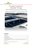
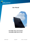
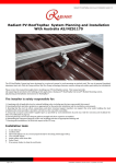
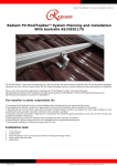
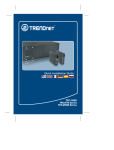
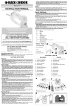
PV-ezRack® SolarRoof™ Code-Compliant Planning and Installation Complying with AS/NZS1170.2:2011 ADMT 2-2012 CONTENT 1. 2. 3. 4. 5. 6. Introduction…………………………………………………………………………………………………… 2 Planning…………………………………………………………………………………………………………. 3 Component List……………………………………………………………………………………………… 8 Array planning……………………………………………………………………………………………….. 9 Step by step installation………………………………………………………………………………… 10 Service……………………….…………………………………………………………………………………..18 Installation Guide_PV-ezRack_SolarRoof_AU_V2.3 18/20 Duerdin St Clayton VIC 3168, Australia www.clenergy.com.au Page 1 of 18 Tel: +61 3 9017 6688 Fax: +61 3 9017 6668 Email: [email protected] Introduction ® The Clenergy PV-ezRack SolarRoof™ has been developed as a universal PVmounting system for roof-mounting on pitched and flat roofs. The use of patented aluminium base rails, the Z-Module technology and the telescopic mounting technology eliminates custom cutting and enables particularly fast installation. ® Please review this manual thoroughly before installing PV-ezRack SolarRoof™. This manual provides (1) supporting documentation for building permit ® applications relating to PV-ezRack SolarRoof™ Universal PV Module Mounting System, and (2) planning and installation instructions. ® The PV-ezRack SolarRoof™ parts, when installed in accordance with this guide, will be structurally adequate and will meet the AS/NZS1170.2:2011 Admt 22012 standard. During installation and especially when working on the roof please comply with the appropriate occupational health and safety regulations. Please also pay attention to other relevant regulations of your local region. Please check that you are using the latest version of the installation manual, which you can do by contacting Clenergy Australia via email on [email protected], or contacting your local distributor in Australia. Installation Guide_PV-ezRack_SolarRoof_AU_V2.3 18/20 Duerdin St Clayton VIC 3168, Australia www.clenergy.com.au Page 2 of 18 Tel: +61 3 9017 6688 Fax: +61 3 9017 6668 Email: [email protected] Planning The installer is solely responsible for: Complying with all applicable local or national building codes and Clean Energy Council guidelines including any that may superseded this manual; ® Ensuring that PV-ezRack SolarRoof™ and other products you use are appropriate for the particular installation and the installation environment; Ensuring that the roof, its rafters, connections, and other structural support members can support the array under building live load conditions (this total assembly is hereafter referred to as the roof rafter assembly); ® Using only genuine PV-ezRack parts (substitution of parts may void the warranty and invalidate the letter of certification); Ensuring that lag screws have adequate pull-out strength and shear capacities as installed; Maintaining the waterproof integrity of the roof, including selection of appropriate flashing; and Ensuring safe installation of all electrical aspects of the PV array ® This document is designed to support for installations using PV-ezRack SolarRoof™ PV Module Mounting System, manufactured by Clenergy (Xiamen) Technology Co., Ltd. Follow the steps below and the installation instructions section to install this product in compliance with the AS/NZS1170.2:2011 ADMT 2-2012. Before proceeding, note the following: This document addresses only wind loads on the assumption that wind produces the maximum load factor affecting an installation. Verify that other local factors, such as snow loads and earth quake effects, do not exceed the wind loads. Give precedence to any factor that does. Wind loads are considered to act on the entire projected area, or may be perpendicular to any surface. ® The roof on which the PV-ezRack SolarRoof™ will be installed must have the capacity to resist the combined Design Dead Load and Live Load per footing. To determine the parts (Bill of material) you need you can use our PV® ezRack SolarRoof™ Calculator. Installation Guide_PV-ezRack_SolarRoof_AU_V2.3 18/20 Duerdin St Clayton VIC 3168, Australia www.clenergy.com.au Page 3 of 18 Tel: +61 3 9017 6688 Fax: +61 3 9017 6668 Email: [email protected] 1. Determine the wind region of your installation site Region Definition: Wind regions are pre-defined for all of Australia by the Australian Standard 1170.2. The Wind Region is an independent factor of surrounding topography or buildings. Most of Australia is designated Region A which indicates a Regional Ultimate Basic Wind Velocity of 45m/s. Some areas are designated Region B (57m/s). Local authorities will advise if this applies in your area. Region C areas (66m/s) are generally referred to as Cyclonic and are generally limited to northern coastal areas. Most Region C zones end 100km inland. Region D (80m/s) Australia's worst Cyclonic Region between Carnarvon and Pardoo in Western Australia. Installation Guide_PV-ezRack_SolarRoof_AU_V2.3 18/20 Duerdin St Clayton VIC 3168, Australia www.clenergy.com.au Page 4 of 18 Tel: +61 3 9017 6688 Fax: +61 3 9017 6668 Email: [email protected] 2. Determine the Terrain Category You will need to determine the terrain category that is most applicable to the installation. Terrain Category 1 (TC1) – Very exposed open terrain with few or no obstructions and enclosed, limited-sized water surfaces at serviceability and ultimate wind speeds in all wind regions, e.g. flat, treeless, poorly grassed plains; rivers, canals and lakes; and enclosed bays extending less than 10km in the wind direction. Terrain Category 1.5 (TC1.5) – Open Water surfaces subjected to shoaling waves at serviceability and ultimate wind speeds in all win regions, e.g. near-shore ocean water; larger unenclosed bays on seas and oceans; lakes; and enclosed bays extending greater than 10km in the wind direction. The terrain height multipliers for this terrain category shall be obtained by the linear interpolation between the values for the TC1 and TC2 in table 4.1. Terrain Category 2 (TC2) – Open terrain, including grassland, with wellscattered obstructions having heights generally from 1.5m to 5m, with no more than two obstructions per hectare, e.g. farmland and cleared subdivisions with isolated trees and uncut grass. Terrain Category 2.5 (TC2.5) – Terrain with a few trees or isolated obstructions. This category is intermediate between TC2 and TC3 and represents the terrain in developing outer urban areas scattered houses, or larger acreage developments with fewer than ten buildings per hectare. The terrain-height multipliers for this terrain category shall be obtained by linear interpolation between the values for the TC2 and TC3 in table 4.1. Terrain Category 3 (TC3) – Terrain with numerous closely spaced obstruction having heights generally from 3m to 10m. The minimum density f obstructions shall be at least the equivalent of 10 house sizes obstructions per hectare, e.g. suburban housing or light industrial estates. Terrain Category 4 (TC4) – Terrain with numerous larger, high (10m to 30m tall) and closely-spaced constructions, such as large city centres and well-developed industrial complexes. Note: In this installation manual we have used terrain category 3, if it is outside of this please refer to the accreditation letter. Installation Guide_PV-ezRack_SolarRoof_AU_V2.3 18/20 Duerdin St Clayton VIC 3168, Australia www.clenergy.com.au Page 5 of 18 Tel: +61 3 9017 6688 Fax: +61 3 9017 6668 Email: [email protected] 3. Determine the height of your installation site ® This document provides sufficient information for the PV-ezRack SolarRoof™ system installation up 20 meter height. If your installation site is more than 20 meters please contact Clenergy to obtain additional engineering certificate to support your installation. 4. Determine Roof slope The PV-ezRack® SolarRoof™ system can be used for roof slope up to 60 degrees. Please verify that the Installation site roof slope is between 0 and 60 degrees. 5. Determine the Maximum Rail Support Spacing a) Tile roof Please use the following table to determine the base rail support spacing for tile roof installations (mm). Max PV panel dimension: 2000mm x 1000mm. Max panel weight: 15 kg/m2. Roof Angle: 20˚~ 60˚, Terrain Category 3(for roof pitch 30°-60° refer to accreditation letter) 10°-20° pitch Wind Region A B C D H≤10 Building Height – H (m) 10<H≤15 15<H≤20 1476 1025 655 418 1253 877 563 361 1105 777 501 322 20°-30° pitch Wind Region A B C D H≤10 1589 1115 710 452 Building Height – H (m) 10<H≤15 1366 952 610 390 15<H≤20 1203 843 543 348 Please consult Clenergy for installing PV modules with a greater length than 2000mm or heavier than 15 kg/m2. In case the wooden rafters/trusses you wish to mount on are too thin and the screws would be too close to the edge of the rafters please pre-drill with a 3-4mm pilot hole in order to avoid the splitting of the timber (or use the side mount roof hook ER-I-26). Installation Guide_PV-ezRack_SolarRoof_AU_V2.3 18/20 Duerdin St Clayton VIC 3168, Australia www.clenergy.com.au Page 6 of 18 Tel: +61 3 9017 6688 Fax: +61 3 9017 6668 Email: [email protected] b) Tin roof Please use the following table to determine the base rail support spacing for sheet metal roof installations (mm). Max PV panel length: 2000mm, Max panel weight: 15 kg/m2, Terrain Category 3 Roof Angle ≤ 10° Wind Region A B C D H≤10 1673 1521 1355 1208 Building Height – H (m) 10<H≤15 1602 1461 1304 1164 15<H≤20 1551 1416 1266 1131 Roof Angle 10°-20° Wind Region A B C D H≤10 1554 1419 1269 1134 Building Height – H (m) 10<H≤15 1492 1365 1222 1093 15<H≤20 1446 1324 1187 1062 Roof Angle 20°-30° Wind Region A B C D H≤10 1589 1449 1294 1156 Building Height – H (m) 10<H≤15 1525 1393 1246 1114 15<H≤20 1477 1351 1210 1083 Roof Angle 30°-60° Wind Region A B C D H≤10 1570 1478 1359 1214 Building Height – H (m) 10<H≤15 1529 1436 1311 1170 15<H≤20 1497 1404 1272 1137 Please consult Clenergy for installing PV modules with a greater length than 2000mm or heavier than 15 kg/m2. The L-Feet (ER-I-05) should be fixed to the purlins under using one 12g (6mm) screw through sheet metal roofs with gasket. The above spacing applies for fixing through thin sheet purlins (thickness ≥ 0.55mm) or a minimum embedment of 35mm into timber purlins. Please note that the screws provided with our products are designed for mounting in to wooden structures (10TPI). Clenergy recommend using 12G 14TPI screws (or M6 Buildex RoofZips®) to fix to steel purlins. Installation Guide_PV-ezRack_SolarRoof_AU_V2.3 18/20 Duerdin St Clayton VIC 3168, Australia www.clenergy.com.au Page 7 of 18 Tel: +61 3 9017 6688 Fax: +61 3 9017 6668 Email: [email protected] General Notes Recommended screws: Metal Purlins/Battens 0.55 mm – 1.5 mm 1.9 mm 2.4 mm and Above Fasteners to use M6-11 TPI RoofZips® M6-11 TPI RoofZips® OR 12g-14 TPI Teks screws 12g-24 TPI Teks screws Wood purlins and Rafter Pine and Hardwood (35mm embedment and above) Fasteners to use M6-11 TPI RoofZips® OR 14g-10 TPI Screws minimum embedment length into timber 35 mm Above Spacing calculated based on 1.9mm steel purlin OR F17 Hardwood In wind region C and D the spacing on should be reduced as shown below. Material 0.55 mm steel Batten 0.75 mm steel Batten Wind Region C 25% 0% Wind Region D 42% 5% 6. Verify acceptable Rail End Overhang Rail End Overhang must equal 50% or less of foot spacing. Thus, if foot spacing is 1200 mm, the Rail End Over hang can be up to 600 mm. In this case, two feet can support a rail of as much as 2400 mm (1200 mm between the feet and 600 mm of overhang at each end). Installation Guide_PV-ezRack_SolarRoof_AU_V2.3 18/20 Duerdin St Clayton VIC 3168, Australia www.clenergy.com.au Page 8 of 18 Tel: +61 3 9017 6688 Fax: +61 3 9017 6668 Email: [email protected] Components List Installation tools 6 mm Allen key; Cordless drill Use ONLY stainless steel sockets Open-end spanner set 9, 10, 17, 19 mm (required only for mounting with hanger bolts); Angle grinder with stone disk; Power Cord; Overview of system components for Tile Roof ® ® PV-ezRack Standard Rail PV-ezRack Standard Splice Tile interface (Roof Hook) with Z-Module Wood screw 6x80mm Inter Clamp with Z-Module End Clamp with Z-Module Overview of system components for Tin Roof ® PV-ezRack Standard Rails Tin Interface (L-Feet) with Z-Module ® PV-ezRack Standard Splice End Clamp with Z-Module Wood screw 6x90mm Installation Guide_PV-ezRack_SolarRoof_AU_V2.3 18/20 Duerdin St Clayton VIC 3168, Australia www.clenergy.com.au Inter Clamp with Z-Module Page 9 of 18 Tel: +61 3 9017 6688 Fax: +61 3 9017 6668 Email: [email protected] Preparation Overview of system components ® a PV-ezRack rails b Inter Clamp c Roof hook (Tile Interface) d Splice e End Clamp Planning the module area 1. Number of modules in the vertical direction x module height (please check the installation manual of the Solar module manufacturer) 2. Number of modules in horizontal x (module width + 18mm) + 32mm 3. Horizontal spacing of the roof hooks up to 2.0 m 4. Vertical spacing of the roof hooks = approx. 1⁄2 to 3⁄4 of module height 5. Distance between the modules: 17 mm 6. Always check the installation manual of the PV-Module you use in order to determine the allowed fixing points on the Module frame Installation Guide_PV-ezRack_SolarRoof_AU_V2.3 18/20 Duerdin St Clayton VIC 3168, Australia www.clenergy.com.au Page 10 of 18 Tel: +61 3 9017 6688 Fax: +61 3 9017 6668 Email: [email protected] Step by Step Installation Interface (Tile Roof Hook & Tin Interface) Installation 1. Determine the positions of the roof hooks according to your plans. Remove the roof tiles at the marked positions or, if possible, simply push them up slightly. 2. Fix the roof hooks to the rafter using two 6 x 80mm wood screws. Use ONLY stainless steel sockets (using normal steel socket can result surface rust on the wood screw) 3. The roof hook must not press against the roof tile. If necessary, shim the roof hook with wood. Incorrect Correct 4. If necessary, use an angle grinder or hammer to cut a recess in the tile that covers the roof hook at the point where the roof hook comes through so that the tile lies flat on the surface. If grooved tiles are used, it will also be necessary to cut a recess in the lower tile. For high profile (Spanish) tiles a Roof Hook Extender can be used. Installation Guide_PV-ezRack_SolarRoof_AU_V2.3 18/20 Duerdin St Clayton VIC 3168, Australia www.clenergy.com.au Page 11 of 18 Tel: +61 3 9017 6688 Fax: +61 3 9017 6668 Email: [email protected] Interface (Tile Roof Hook & Tin Interface) Installation 5. Caution! Do not use fitted roof hooks as a ladder, as this extreme point load could damage the tile below. 6. Variation for installation on plain tile roofs with plain tile roof cladding, a recess must be cut into the tiles around the position of the roof hook. 7. General Information for using Z-Module connection: to ensure easy connection of the roof hooks with the rail using the Z-Module, you should make sure that the thread of the bolt does not project through the lower side of the Z-Module (max. flush). Position the Z-Module in the rail channel and fasten it loosely with 2 to 3 turns of the bolt. The bolts can be then freely moved in the rail channel. Slide the bolts to their final and fasten firmly (recommended torque is 15-20Nm). 8. Installation of the rails on roof hooks: if the PV® ezRack rails consist of different lengths, always begin with the shortest piece. Install the framing for each row of modules loosely on the roof hooks, using an M8 x 25 mm Allen bolt, washers, retaining washers and the ZModule (2 to 3 turns of the screw are adequate for loose installation). 9. Adjust to necessary vertical and horizontal position by using the slot hole in the roof hooks and connection of the Z-Module or on the rail. Installation Guide_PV-ezRack_SolarRoof_AU_V2.3 18/20 Duerdin St Clayton VIC 3168, Australia www.clenergy.com.au Page 12 of 18 Tel: +61 3 9017 6688 Fax: +61 3 9017 6668 Email: [email protected] Tin Interface (L-feet) Installation 9.1. In case you need to install on corrugated tin roof cladding the Tin Interface (LFeet) is to be used. Drill through the roof cladding at the planned location and use the supplied wood screws to fix the L-Feet to the wooden purlin. If you need to fix to metal purlin please use suitable metal screws (14TPI ® or Buildex RoofZips®) with the same 6mm diameter. 9.2. Place the supplied EPDM rubber under the L-Feet in the way that the screw goes through the hole in the EPDM rubber pad. When fastening the screw make it sure that you don’t deform the corrugation of the roof cladding. This can happen if you penetrate too deep with the screw when fastening. Installation Guide_PV-ezRack_SolarRoof_AU_V2.3 18/20 Duerdin St Clayton VIC 3168, Australia www.clenergy.com.au Page 13 of 18 Tel: +61 3 9017 6688 Fax: +61 3 9017 6668 Email: [email protected] PV-Module Installation 13. Before installing the modules, add anti-slip protection to the lowest row of modules (horizontal rail installation only). To do this, fasten M6 x 20 mm bolts (with the shank downwards) to the lower mounting holes of the module frame using M6 nuts. When installing large modules M8 x 20mm bolts must be used. 14. Place the first module of the bottom row so that the anti-slip protection sits in the rail channel of the lowest row of rails. 15. Slide the module end clamp tightly against the module and fasten tightly using the Allen bolt (recommended torque is 1520Nm). 16. Cross-section through the module end clamp when installation step 15 has been correctly performed. 17. Insert the pre-assembled inter-module clamp into the rails from above, place it firmly against the module and fasten loosely (approx. 2 - 3 turns). Installation Guide_PV-ezRack_SolarRoof_AU_V2.3 18/20 Duerdin St Clayton VIC 3168, Australia www.clenergy.com.au Page 14 of 18 Tel: +61 3 9017 6688 Fax: +61 3 9017 6668 Email: [email protected] PV-Module Installation 18. Now slide the next module against the previously installed module. Ensure that the vertical side of the module frame is in contact with the vertical surface of the Inter-clamp (no gap between inter-clam and panel). Tighten the inter-module clamp using the Allen key (recommended torque is 15-20Nm). Ensure that the anti-slip protection sits in the rail channel of the lowest row of rails. 19. Place the last PV-Module in the row on the rails and fasten the last inter-module clamp and the module endclamp using the Allen key (torque 15-20Nm). 20. Now slide in the first module of the next row from above onto the corresponding PV module of the row beneath. A separation from the lower module can be maintained for optical reasons. An intermodule clamp can be used as a separator, so that the vertical and horizontal separation of the modules is identical. Continue mounting the PV-Modules as described in steps 15 to 20 until all PV modules are installed. Installation Guide_PV-ezRack_SolarRoof_AU_V2.3 18/20 Duerdin St Clayton VIC 3168, Australia www.clenergy.com.au Page 15 of 18 Tel: +61 3 9017 6688 Fax: +61 3 9017 6668 Email: [email protected] Accessories Isolator Bracket Installation 1. Position the Z Module in the rail channel. Fix the bracket with bolt. (Recommended bolt torque 15-20Nm) 2. The final installation with the isolator mounted Installation Guide_PV-ezRack_SolarRoof_AU_V2.3 18/20 Duerdin St Clayton VIC 3168, Australia www.clenergy.com.au Page 16 of 18 Tel: +61 3 9017 6688 Fax: +61 3 9017 6668 Email: [email protected] Cable Clip Installation 1. Hook the top end of clip into the groove on the back of the rail. 2. Push the other end of clip in to the rail groove. You can use a rubber mallet. 3. cable clip installation completed 4. The cable clip can hold up to 6 PV cables. Installation Guide_PV-ezRack_SolarRoof_AU_V2.3 18/20 Duerdin St Clayton VIC 3168, Australia www.clenergy.com.au Page 17 of 18 Tel: +61 3 9017 6688 Fax: +61 3 9017 6668 Email: [email protected] Service 10 year limited Product Warranty, 5 year limited Finish Warranty Clenergy co. Ltd warrants to the original purchaser (“Purchaser”) of product(s) that it manufactures (“Product”) at the original installation site that the Product shall be free from defects in material and workmanship for a period of ten (10) years, except for the anodised finish, which finish shall be free from visible peeling, or cracking or chalking under normal atmospheric conditions for a period of five (5) years, from the earlier of 1) the date the installation of the Product is completed, or 2) 30 days after the purchase of the Product by the original Purchaser (“Finish Warranty”). The Finish Warranty does not apply to any foreign residue deposited on the finish. All installations in corrosive atmospheric conditions are excluded. The Finish Warranty is VOID if the practices specified by AAMA 609 & 610-02 – “Cleaning and Maintenance for Architecturally Finished Aluminum” (www.aamanet.org) are not followed by Purchaser. This Warranty does not cover damage to the Product that occurs during its shipment, storage, or installation. This Warranty shall be VOID if installation of the Product is not performed in accordance with Clenergy’s written installation instructions, or if the Product has been modified, repaired, or reworked in a manner not previously authorized by Clenergy IN WRITING, or if the Product is installed in an environment for which it was not designed. Clenergy shall not be liable for consequential, contingent or incidental damages arising out of the use of the Product by Purchaser under any circumstances. If within the specified Warranty periods the Product shall be reasonably proven to be defective, then Clenergy shall repair or replace the defective Product, or any part thereof, in Clenergy’s sole discretion. Such repair or replacement shall completely satisfy and discharge all of Clenergy’s liability with respect to this limited Warranty. Under no circumstances shall Clenergy be liable for special, indirect or consequential damages arising out of or related to use by Purchaser of the Product. Manufacturers of related items, such as PV modules and flashings, may provide written warranties of their own. Clenergy’s limited Warranty covers only its Product, and not any related items. Installation Guide_PV-ezRack_SolarRoof_AU_V2.3 18/20 Duerdin St Clayton VIC 3168, Australia www.clenergy.com.au Page 18 of 18 Tel: +61 3 9017 6688 Fax: +61 3 9017 6668 Email: [email protected]