1
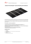
Radiant PV-RoofTopRac planning and Installation Guide V1.5 Radiant PV-RoofTopRac System Planning and Installation With Australia AS/NZS1170 The PV-RoofTopRac System has been developed as a universal system for roof-mounting on pitched roofs. The use of patented (pending) aluminium base rails, Click-In Clamp and Base Rail Pre-Clamp technology eliminates custom cutting and enables particularly fast installation. Please review this manual thoroughly before installing your PV-RoofTopRac system. This manual provides (1) supporting documentation for building permit applications relating to PV-RoofTopRac Universal PV Module Mounting system, (2) planning and installation instructions for RooftopRac™. The installer is solely responsible for: 1. Complying with all applicable local or national building codes, including any that may superseded this manual; 2. Ensuring that Rack and other products are appropriate for the particular installation and the installation environment; 3. Ensuring that the roof, its rafters, connections, and other structural support members can support the array under building live load conditions (this total assembly is hereafter referred to as the roof rafter assembly); 4. Using only rack parts and installer-supplied parts as specified by rack (substitution of parts may void the warranty and invalidate the letter of certification on page 2); 5. Ensuring that lag screws have adequate pullout strength and shear capacities as installed; 6. Maintaining the waterproof integrity of the roof, including selection of appropriate flashing; and 7. Ensuring safe installation of all electrical aspects of the PV array. Installation tools 1. 2. 3. 4. 5. 6. 7. 6 mm Allen key; Cordless drill; Open-end spanner set 10, 13 mm (required only for mounting with hanger bolts); Torx-30 (AW 30) bit; Angle grinder with stone disk; Power Cord; If necessary, timber to shim the roof hooks. Page 1 of 11 RooftopRac installation manual-Version 1.5(updated Apr 2013) Radiant PV-RoofTopRac planning and Installation Guide V1.5 Code-Compliant Planning This document is designed to support for installations using PV-RoofTopRac Module Mounting System, manufactured by Radiant Co. Ltd. Follow the six steps below and the installation instructions section to install PV-RoofTopRac in compliance with the AS/NZS1170. Before proceeding, note the following: This document addresses only wind loads on the assumption that wind produces the maximum load factor affecting an installation. Verify That other local factors, such as snow loads and earth quake effects, do not exceed the wind loads. Give precedence to any factor that does. Wind loads are considered to act on the entire projected area, or may be perpendicular to any surface. The roof on which the PV-RoofTopRac will be installed must have the capacity to resist the combined Design Dead Load and Live Load per Footing. 1. Determine the wind region of your installation site(in accordance with AS/NZS1170.2:2011) Region Definition: Wind regions are pre defined for all of Australia by Australian Standard 1170. The Wind Region has nothing to do with surrounding topography or buildings. Most of Australia is designated Region A which indicates a Regional Ultimate Basic Wind Velocity of 45msec. Some areas are designated Region B (57msec). Local authorities will advise if this applies in your area. Region C areas (66msec) are generally refered to as Cyclonic and are generally limited to northern coastal areas. Most Region C zones end 100km inland. Region D (80msec) Australia's worst Cyclonic Region between Carnarvon and Pardoo in Western Australia. 2. Determine the height of the of your installation site This document provides sufficient information for PV-RoofTopRac system installation height less then 20 meters. If your installation site is more than 20 meters in height, please contact Radiant to obtain engineering data to support your installation. Page 2 of 11 RooftopRac installation manual-Version 1.5(updated Apr 2013) Radiant PV-RoofTopRac planning and Installation Guide V1.5 3. Determine the Maximum Rail Support Spacing Please use the following table to determine the base rail 40 support spacing for tile roof installations. ROOF ZONE Internal zone Edge zone MAXIMUM RAFTER SPACING ‘S’ IN mm, FOR TILE ROOFS Installation Height Region A (mm) Region B (mm) Region C (mm) 5 Meters 1600 1500 1100 10 Meters 1510 1250 1000 15 Meters 1450 1180 920 20 Meters 1380 1100 860 5 Meters 800 750 550 10 Meters 755 625 500 15 Meters 725 590 460 20 Meters 690 550 430 Region D (mm) 1020 910 850 790 510 455 425 390 Please use the following table to determine the base rail 34 support spacing for tile roof installations. ROOF ZONE Internal zone Edge zone MAXIMUM RAFTER SPACING ‘S’ IN mm, FOR TILE ROOFS Installation Height Region A (mm) Region B (mm) Region C (mm) 5 Meters 1450 1400 1050 10 Meters 1400 1200 980 15 Meters 1300 1090 880 20 Meters 1250 1030 820 5 Meters 750 700 500 10 Meters 700 600 450 15 Meters 650 550 410 20 Meters 600 500 390 Region D (mm) 950 860 800 740 450 400 380 330 The above figures are based on modules lengths of up to 2000mm, maximum weight of 29Kg 2000mm modules requires 2 rails with fixing as per table above The above spacing applies for fixing through thin sheet purlins (greater than 1.0mm thickness) or a minimum embedment of 50mm into Timber purlins. Tile brackets should fixed to the rafter using two timber screws (6.3x80mm) As below figure: Page 3 of 11 RooftopRac installation manual-Version 1.5(updated Apr 2013) Radiant PV-RoofTopRac planning and Installation Guide V1.5 Please use the following table to determine the base rail 40 support spacing for sheet metal roof installations. MAXIMUM FIXING IN ‘mm’ SPACING FOR TIMBER BATTENS/PURLINS FOR TIN ROOFS ROOF ZONE Installation Height Region A & B (mm) Region C & D (mm) 5 Meters 1400 1020 10 Meters 1250 980 Internal zone 15 Meters 1160 920 20 Meters 1100 880 5 Meters 700 510 10 Meters 625 490 Edge zone 15 Meters 580 460 20 Meters 550 440 Please use the following table to determine the base rail 34 support spacing for sheet metal roof installations. MAXIMUM FIXING IN ‘mm’ SPACING FOR TIMBER BATTENS/PURLINS FOR TIN ROOFS ROOF ZONE Installation Height Region A & B (mm) Region C & D (mm) 5 Meters 1300 990 10 Meters 1150 930 Internal zone 15 Meters 1090 890 20 Meters 1050 830 5 Meters 650 450 10 Meters 600 400 Edge zone 15 Meters 540 380 20 Meters 500 350 The above figures are based on modules lengths of up to 2000mm, maximum weight of 29Kg 2000mm modules requires 2 rails with fixing as per table above The above spacing applies for fixing through thin sheet purlins (greater than 1.0mm thickness) or a minimum embedment of 50mm into timber purlins. Based on an embedment depth of 35mm (fixing into the battens) the spacings remain unchanged for region A and B. For region C, the spacings should be reduced by 10% and for region D, the spacings should be reduced by 30%. The wave support should be fixed to the purlins under using one timber Screw (6.3x80mm) through sheet metal roofs with desk rubber. Page 4 of 11 RooftopRac installation manual-Version 1.5(updated Apr 2013) Radiant PV-RoofTopRac planning and Installation Guide V1.5 Please use the following table to determine the base rail 40 support spacing for Klip lok roof installations. MAXIMUM FIXING IN ‘mm’ SPACING FOR KLIP LOK CLAMP FOR KLIP LOK ROOFS ROOF ZONE Installation Height Region A & B (mm) Region C & D (mm) 5 Meters 1500 1120 10 Meters 1350 1080 Internal zone 15 Meters 1250 1000 20 Meters 1150 950 5 Meters 750 560 10 Meters 675 540 Edge zone 15 Meters 625 500 20 Meters 570 475 Please use the following table to determine the base rail 34 support spacing for Klip lok roof installations. MAXIMUM FIXING IN ‘mm’ SPACING FOR KLIP LOK CLAMP FOR KLIP LOK ROOFS ROOF ZONE Installation Height Region A & B (mm) Region C & D (mm) 5 Meters 1400 1020 10 Meters 1250 990 Internal zone 15 Meters 1150 900 20 Meters 1050 850 5 Meters 700 500 10 Meters 640 490 Edge zone 15 Meters 590 450 20 Meters 530 400 The above figures are based on modules lengths of up to 2000mm, maximum weight of 29Kg 2000mm modules requires 2 rails with fixing as per table above The above spacing applies for fixing through Klip Lok roof Fix Klip lok clamp recommend torque is 25Nm 4. Verify acceptable Rail End Overhang Rail End Overhang must equal 50 percent or less of foot spacing. Thus, if foot spacing is 1200mm, the Rail End Over hang can be up to 600mm. In this case, two feet can support a rail of as much as 2400mm (1200mm between the feet and 600mm of overhang at each end). 5. Determine Roof slope PV-RoofTopRac system can be used for roof slope up to 60 degrees. Please verify the Installation site roof slope should be between 0 degrees and 60 degrees. Page 5 of 11 RooftopRac installation manual-Version 1.5(updated Apr 2013) Radiant PV-RoofTopRac planning and Installation Guide V1.5 6. Determine Roof Installation Roof Areas A typical procedure in calculating the maximum building height for the installation of solar panel is given above .If you know the building height ,terrain category ,wind region and roof pitch ,then you can determine the edge distance as well. A roof can be divided into two zones, the internal zone and the edge zone. The width of these outer zones can be determined based on the length, width and average height of the building. If fixings are located in the internediate or edge zones, then the maximum spacing to the next fixing must be reduced, as per the table in the drawings PV-RoofTopRac Components for Roof Installation Overview of system components Base Rail40 Base Rail 34 Modules middle Clamp Modules End Clamp RoofHook45/136-166 Wave support (for Tin Roof) Base Rail40/60 Splice galvanised Corrugated Screw 6x80mm with Gaske Page 6 of 11 RooftopRac installation manual-Version 1.5(updated Apr 2013) Radiant PV-RoofTopRac planning and Installation Guide V1.5 Installation preparation Overview of system components Planning the module area 1. Number of modules in the vertical direction x module height (please check also the installation manual of the manufacturer of the solar module) 2. Number of modules in horizontal direction x (module width + 23.5 mm) + 30 mm 3. Horizontal spacing of the roof hooks up to 2.0 m* 4. Vertical spacing of the roof hooks = approx. 1⁄2 to 3⁄4 of module height 5. Distance between the modules: 23.5 mm * Caution: Installations that are exposed to the wind or are located on the edge or corners of the roof may make it necessary to leave smaller spaces between modules. Page 7 of 11 RooftopRac installation manual-Version 1.5(updated Apr 2013) Radiant PV-RoofTopRac planning and Installation Guide V1.5 Installation Instruction Roof Hook Installation 1. Determine the positions of the roof hooks according to your plans. Remove the roof tiles at the marked positions or, if possible, simply lift them up slightly. 2. Fix the roof hooks to the rafter using 6 x 80 mm timber screws. 3.The roof hook must not press against the roof tile. If necessary, shim the roof hook with wood. 4.If necessary, use an angle grinder or hammer to cut a recess in the tile that covers the roof hook at the point where the roof hook comes through so that the tile lies flat on the surface. If grooved tiles are used, it will also be necessary to cut a recess in the lower tile. 5. Caution! Do not use fitted roof hooks as a ladder, as this extreme point load could damage the tile below . Page 8 of 11 RooftopRac installation manual-Version 1.5(updated Apr 2013) Radiant PV-RoofTopRac planning and Installation Guide V1.5 Wave support Installation 6.Variation for installation on corrugated metal, In the case of corrugated roof cladding, wave support are used instead of roof hooks. Drill through the roof cladding at the planned location and screw the timber screw into the purloins. Then mount the brackets. 7. Cross-section of a wave support installation. Take special care that the timber screw tightly fastens the sealing washer without damaging the roof cladding. When performing the installation, take care that the thread of the wood screw not cover the long hole in the bracket. Base Rail Installation 8.Installation of the rails on roof hooks ,If your set of rails consists of rails of different lengths, always begin with the shortest piece. Install the framing for each row of modules loosely on the roof hooks, put the base rail slide into klicktop of roofhook, and fasten tightly using the nut. (recommended torque is 18 Nm). 10.An optimum adjustment of the vertical and horizontal position can be made by taking advantage of the long hole in the roof hooks and fasten tightly using the nut. (recommended torque is 18 Nm). 11.Position the first frame rails for each row and fasten them temporarily to the roof cladding using a cord. Tighten the allen the nuts on the Klicktop nut that are used to fasten the roof hooks/hanger bolts (recommended torque is 18 Nm). Please also pay attention to Figure 10. Page 9 of 11 RooftopRac installation manual-Version 1.5(updated Apr 2013) Radiant PV-RoofTopRac planning and Installation Guide V1.5 Splice Installation 12.Installation of the splice with base rails to connect multiple rails together, put the splices under the rails halfway, put other rail on the halfway. Fasten the first M10*12 Allen bolt firmly using the Allen key. Fasten the other side M10*12 Allen bolt firmly using the Allen key. 13. Tighten the second M10*12 Allen bolt using the Allen key. Fasten the other side M10*12 Allen bolt firmly using the Allen key .The connection is finished. PV Module Installation 14. Put the module end clamp inset the base rail, tightly against the module and fasten tightly using the Allen bolt (recommended torque is 15 Nm). 15. Put module middle clamp inset the rails from above, place it firmly against the module and fasten loosely (approx. 2 - 3 turns). Now inset the next module against the previously installed module and tighten the inter-module clamp using the Allen key (recommended torque is 15 Nm). 16. Put rail cap into the base rail, Continue mounting the modules as described in steps 14 to 16 until all modules are installed. The installation is finished. Page 10 of 11 RooftopRac installation manual-Version 1.5(updated Apr 2013) Radiant PV-RoofTopRac planning and Installation Guide V1.5 15 Years Standard Warranty Terms and Conditions RADIANT International (“RADIANT”) warrants to the original purchaser (“Purchaser”) of product(s) that it manufactures (“Product”) at the original installation site that the Product shall be free from defects in material and workmanship for a period of ten (15) years, except for the anodized finish which shall be free from visible peeling, or cracking or chalking under normal atmospheric conditions, from the earlier of: 1). the date the installation of the Product is completed, or; 2). 30 days after the purchase of the Product by the original Purchaser. The Warranty does not apply to any foreign residue deposited on the finish. All installations in corrosive atmospheric conditions are excluded. The Warranty is VOID if the practices specified by AAMA 609 & 610-02 – “Cleaning and Maintenance for Architecturally Finished Aluminium” (www.aamanet.org) are not followed by Purchaser. This Warranty does not cover damage to the Product that occurs during its shipment, storage, or installation. This Warranty shall be VOID if installation of the Product is not performed in accordance with RADIANT’s written installation instructions, or if the Product has been modified, repaired, or reworked in a manner not previously authorized by RADIANT IN WRITING, or if the Product is installed in an environment for which it was not designed. RADIANT shall not be liable for consequential, contingent or incidental damages arising out of the use of the Product by Purchaser under any circumstances. If within the specified Warranty periods the Product shall be reasonably proven to be defective, then RADIANT shall repair or replace the defective Product, or any part thereof, in RADIANT’s sole discretion. Such repair or replacement shall completely satisfy and discharge all of RADIANT’s liability with respect to this Limited Warranty. Under no circumstances shall RADIANT be liable for special, indirect or consequential damages arising out of or related to use by Purchaser of the Product. Manufacturers of related items, such as PV modules and flashings, may provide written warranties of their own. RADIANT’s Limited Warranty covers only its Product, and not any related items. Page 11 of 11 RooftopRac installation manual-Version 1.5(updated Apr 2013)