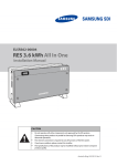
1
ELSR362-00002 RES 3.6 kWh All In One Installation Manual CAUTION Do not operate with other components not approved by the ESS systems. (Connecting other products in parallel to Samsung SDI's products may result in abnormal operation.) The internet connection is required to use all functions of the ESS system. If you have a problem, please contact the installer. The Specifications of the product may be modified without prior notice to improve product quality. United Kingdom (Eng.) 05/2015. Rev1.1 Table of Contents Table of Contents Table of Contents ......................................................................................................... i Table of Tables ........................................................................................................... iv Table of Figures ........................................................................................................... v 1. About this Manual ................................................................................................. 1 1.1 1.2 1.3 1.4 Valid Range ................................................................................................................................................. 1 Target Group .............................................................................................................................................. 1 Manual Storage ......................................................................................................................................... 1 Symbols Used ............................................................................................................................................ 1 2. Safety ...................................................................................................................... 4 2.1 2.2 2.3 Intended Use.............................................................................................................................................. 4 Safety Precautions .................................................................................................................................... 5 Product Overview..................................................................................................................................... 6 2.3.1 Basic Specifications .................................................................................................................... 7 2.3.2 Grounding the PV Inverter ....................................................................................................... 7 3. Package Removal and Inspection ......................................................................... 8 3.1 Package Removal and Tray Assembly................................................................................................. 8 3.1.1 Removing the Enclosure Package ......................................................................................... 8 3.1.2 Removing the Battery Tray Package...................................................................................... 9 3.1.3 Checking Components on the Packing List..................................................................... 10 3.1.4 Assembling the Battery Tray .................................................................................................. 11 3.2 3.3 Checking for damage in Delivery ..................................................................................................... 12 Identifying Samsung 3.6 kWh All in One ........................................................................................ 12 4. Installation ........................................................................................................... 14 4.1 Selection of Installation Location ..................................................................................................... 14 4.1.1 Dimensions and Weight......................................................................................................... 15 4.1.2 Ambient Conditions and Temperatures............................................................................ 15 4.1.3 Minimum Clearance ................................................................................................................ 15 4.1.4 Position (Location Selection)................................................................................................ 16 4.2 Mounting Instructions ......................................................................................................................... 17 5. Electrical Connections ......................................................................................... 20 5.1 5.2 5.3 5.4 5.5 5.6 5.7 The Overview of Electrical Connection........................................................................................... 21 Opening the Front Case Cover .......................................................................................................... 26 The Overview of the Connection Area ............................................................................................ 27 Battery Installation ................................................................................................................................ 28 Inner Wiring Connection (Power and Signal Wire Connection for BMS) .............................. 30 Closing the Front Case Cover ............................................................................................................. 32 A Method of Locking the Distribution Box (Board) ..................................................................... 35 United Kingdom (Eng.) 05/2015. Rev1.1 i Table of Contents 5.7.1 5.7.2 5.8 5.9 AC Circuit Breaker and DC Disconnect Switch ................................................................ 36 RCD (residual current device) Leakage Circuit Breaker ................................................ 36 An Installation Method of Energy Meter Electrical Connection.............................................. 37 A Connecting Method of the DC Line from the PV ..................................................................... 37 6. Communication Connection ............................................................................... 42 6.1 Internet Connection ............................................................................................................................. 42 6.1.1 Components .............................................................................................................................. 42 6.1.2 Connection Block Diagram ................................................................................................... 42 6.1.3 Connection Method ................................................................................................................ 42 6.2 Energy Meter Connection ................................................................................................................... 43 6.2.1 RS485 Interface ......................................................................................................................... 43 6.3 6.4 6.5 Recommended Energy Meter List .................................................................................................... 44 The Communication Terminal ........................................................................................................... 44 Homepage ............................................................................................................................................... 45 6.5.1 Service Terms............................................................................................................................. 45 6.5.2 Membership .............................................................................................................................. 45 6.5.3 Membership Withdrawal ....................................................................................................... 45 6.5.4 Log-In........................................................................................................................................... 45 6.5.5 Password Initialization............................................................................................................ 46 6.5.6 Types of Service Offered ........................................................................................................ 46 6.5.7 Mobile Service .......................................................................................................................... 49 7. Entering Initial Installation Information ............................................................ 50 7.1 7.2 7.3 Information Input Administrator ...................................................................................................... 50 System Information input stage ....................................................................................................... 50 PC Direct Connection and Local Setting Value............................................................................. 50 7.3.1 PC Direct Connection Flow ................................................................................................... 50 7.3.2 Inserting Jumper Wire ............................................................................................................ 51 7.3.3 LAN Cable Connection between PC and System ........................................................... 51 7.3.4 SIM (System Install Manager) Connection ....................................................................... 51 7.3.5 Entering Setting Value ............................................................................................................ 53 7.4 Web Page Connection.......................................................................................................................... 54 7.4.1 Web Page Connection ............................................................................................................ 54 7.4.2 Login & “ESS List ”menu ........................................................................................................ 54 7.4.3 Adding New ESS Information ............................................................................................... 54 7.4.4 Checking the Current Status of ESS.................................................................................... 56 7.4.5 Changing Inverter’s Feed-In Setting .................................................................................. 56 7.4.6 Changing the Inverter’s Output Setting ........................................................................... 58 8. Operation Test ..................................................................................................... 59 8.1 8.2 8.3 ii Starting the System............................................................................................................................... 59 Turning off the System ......................................................................................................................... 59 Descriptions of Operation Mode ...................................................................................................... 60 8.3.1 PV-Auto Mode ........................................................................................................................... 60 8.3.2 PV-Only Mode ........................................................................................................................... 61 United Kingdom (Eng.) 05/2015. Rev1.1 Table of Contents 8.3.3 8.3.4 8.3.5 8.3.6 8.3.7 8.3.8 Battery-Discharge Mode ........................................................................................................ 61 Standby Mode........................................................................................................................... 62 Forced-Charge Mode (Maintenance mode) .................................................................... 62 Stand-Alone Mode .................................................................................................................. 62 Event Check Mode ................................................................................................................... 63 Application Download Mode ............................................................................................... 67 9. Problem Confirmation ......................................................................................... 68 9.1 General Events........................................................................................................................................ 68 9.1.1 INVERTER General Events (Warnings) ................................................................................ 68 9.1.2 INVERTER General Events (Protection) .............................................................................. 69 9.1.3 Battery Discharge General Events ...................................................................................... 71 9.1.4 PV General Events (Protection) ............................................................................................ 73 9.1.5 System General Events (Protection) ................................................................................... 74 9.1.6 BMS General Events ................................................................................................................ 75 9.1.7 EMS/Communication Events ................................................................................................ 76 9.1.8 Single Fault Events................................................................................................................... 77 9.2 Significant Events .................................................................................................................................. 78 10.Maintenance ........................................................................................................ 79 10.1 Cleaning the Fan and the Cover........................................................................................................ 79 10.2 Checking and Exchanging Various Components ........................................................................ 81 10.2.1 Fuse Check ................................................................................................................................. 81 10.2.2 Input / Output Terminal Check ............................................................................................ 81 10.2.3 DC Link Check ........................................................................................................................... 81 10.2.4 FAN Operation Check ............................................................................................................. 82 10.3 Battery Maintenance ............................................................................................................................ 83 10.3.1 Checking Battery Problem .................................................................................................... 83 10.3.2 Battery Exchange Procedure ................................................................................................ 84 10.4 The List of Replaceable Parts ............................................................................................................. 85 10.4.1 Li-Ion Battery Tray .................................................................................................................... 85 10.4.2 PV Connector ............................................................................................................................ 86 10.4.3 FAN 1 & FAN 2 ............................................................................................................................ 86 11.Technical Specifications ...................................................................................... 87 12.Disassembly ......................................................................................................... 91 12.1 Disassembly ............................................................................................................................................ 91 12.1.1 Removing Electric Connection ............................................................................................ 91 12.1.2 Disassembling the Main Body of 3.6 kWh All in One .................................................... 91 12.2 Packaging................................................................................................................................................. 92 12.3 Storage...................................................................................................................................................... 92 12.4 Disposal .................................................................................................................................................... 92 13.Contact ................................................................................................................. 93 United Kingdom (Eng.) 05/2015. Rev1.1 iii Table of Tables Table of Tables [Table 1-1: Symbol Description] .................................................................................................................... 3 [Table 2-1: Part Description] ........................................................................................................................... 6 [Table 2-2: Basic Specifications]..................................................................................................................... 7 [Table 3-1: Component Description] ........................................................................................................ 10 [Table 4-1: Weight of All in One] ................................................................................................................ 15 [Table 4-2: Specifications for anchor bolt] .............................................................................................. 17 [Table 5-1: Component Description] ........................................................................................................ 23 [Table 5-2: Part List] ........................................................................................................................................ 25 [Table 5-3: Front Case Open Process] ....................................................................................................... 26 [Table 5-4: Front and Rear view of All in One]........................................................................................ 27 [Table 5-5: Circuit breaker, DC Disconnection Switch and power line specification] ................ 36 [Table 5-6: RCD Leakage circuit breaker description] .......................................................................... 36 [Table 5-7: Wire Standard]............................................................................................................................ 38 [Table 6-1: Recommended Meter List] ..................................................................................................... 44 [Table 7-1: Registration Item list] ............................................................................................................... 56 [Table 9-1: Inverter general events warning list]................................................................................... 69 [Table 9-2: Inverter protection list] ............................................................................................................ 71 [Table 9-3: Battery operation general events list .................................................................................. 72 [Table 9-4: PV general events protection list] ........................................................................................ 74 [Table 9-5: System general events protection list] ............................................................................... 74 [Table 9-6: BMS general events list] .......................................................................................................... 76 [Table 9-7: EMS/communication events list] .......................................................................................... 76 [Table 9-8: Single fault events list] ............................................................................................................. 77 [Table 9-9: Significant events list] .............................................................................................................. 78 [Table 10-1: Replaceable parts list] ............................................................................................................ 85 [Table 11-1: Technical specifications] ....................................................................................................... 88 iv United Kingdom (Eng.) 05/2015. Rev1.1 Table of Figures Table of Figures [Figure 2-1: Connection Diagram] ................................................................................................................ 4 [Figure 2-2: Part View of Samsung All in One] .......................................................................................... 6 [Figure 3-1: Process for the enclosure package removal]...................................................................... 9 [Figure 3-2: Process for the battery package removal] .......................................................................... 9 [Figure 3-3: Packing List]............................................................................................................................... 10 [Figure 3-4: Process for the battery assembly]....................................................................................... 11 [Figure 3-5: Name Plate] ............................................................................................................................... 13 [Figure 4-1: Dimension of All in One]........................................................................................................ 15 [Figure 4-2: Minimum Clearance for All in One] .................................................................................... 16 [Figure 4-3: Restriction for the surface gradient] .................................................................................. 16 [Figure 4-4: Spanner for fastening anchor nuts] ................................................................................... 17 [Figure 4-5: Anchor Bolt]............................................................................................................................... 17 [Figure 4-6: A Flat head driver for the front cover knob (larger than 10mm)] ............................. 18 [Figure 4-7: The Plus head driver (No.2) for the tray, the side cover, and grounding] .............. 18 [Figure 4-8: A spanner for fastening use] ................................................................................................ 18 [Figure 4-9: A fork lifter with height of 85-200mm] ............................................................................. 19 [Figure 5-1: Electrical connections] ........................................................................................................... 21 [Figure 5-2: PV connections]........................................................................................................................ 22 [Figure 5-3: Front Inside View] .................................................................................................................... 24 [Figure 5-4: Rear Inside View] ...................................................................................................................... 24 [Figure 5-5: Side View] ................................................................................................................................... 25 [Figure 5-6: Rear Inside View] ...................................................................................................................... 28 [Figure 5-7: Battery Tray Rear View] .......................................................................................................... 28 [Figure 5-8: Battery Connection] ................................................................................................................ 28 [Figure 5-9: Battery Docking description] ............................................................................................... 29 [Figure 5-10: Battery to BMS Connection] ............................................................................................... 30 [Figure 5-11: Cable Stuff Method].............................................................................................................. 30 [Figure 5-12: Battery Power Connection] ................................................................................................ 31 [Figure 5-13: Front Cover Assembly process 1] ..................................................................................... 32 [Figure 5-14: Front Cover Assembly process 2] ..................................................................................... 33 [Figure 5-15: Front Cover Assembly process 3] ..................................................................................... 33 [Figure 5-16: Front Cover Assembly process 4] ..................................................................................... 34 [Figure 5-17: Distribution box connection diagram] ........................................................................... 35 [Figure 5-18: Electric cable connection for energy meter installation] .......................................... 37 [Figure 5-19: PV connector (Female) and PV line (Male)] ................................................................... 38 [Figure 5-20: Side cover opening].............................................................................................................. 38 [Figure 5-21: PV connector connection (MC4 connector connection)] ......................................... 39 [Figure 5-22: L and N AC line connection method] .............................................................................. 39 [Figure 5-23: Terminal Block]....................................................................................................................... 40 [Figure 5-24: Power Cable connection to the terminal block] .......................................................... 40 [Figure 5-25: Side view after side cover assembly] ............................................................................... 41 [Figure 6-1: Internet Connection] .............................................................................................................. 42 [Figure 6-2: Energy Meter Wiring & Setting (For C2000M)]................................................................ 43 [Figure 6-3: RS485 terminal block]............................................................................................................. 43 [Figure 6-4: Communication terminal]..................................................................................................... 44 [Figure 6-5: Log-in page] .............................................................................................................................. 45 [Figure 6-6: Password initialization page] ............................................................................................... 46 [Figure 6-7: Monitoring page] ..................................................................................................................... 47 [Figure 6-8: Consumption report page] ................................................................................................... 47 United Kingdom (Eng.) 05/2015. Rev1.1 v Table of Figures [Figure 6-9: Forecast page] .......................................................................................................................... 48 [Figure 6-10: Setting page] .......................................................................................................................... 49 [Figure 6-11: Mobile service page] ............................................................................................................ 49 [Figure 7-1: Jumper] ....................................................................................................................................... 51 [Figure 7-2: Initial setup page] .................................................................................................................... 52 [Figure 7-3: Engineer log in page] ............................................................................................................. 54 [Figure 7-4: New ESS add page] ................................................................................................................. 55 [Figure 7-5: ESS status page] ....................................................................................................................... 56 [Figure 7-6: Inverter feed in limit setup page] ....................................................................................... 57 [Figure 7-7: ESS status detail information page] ................................................................................... 57 [Figure 7-8: ESS output setup page] ......................................................................................................... 58 [Figure 7-9: PCS information page] ........................................................................................................... 58 [Figure 8-1: Initial indication screen on power on]............................................................................... 59 [Figure 8-2: Standby state indication screen before the EMS command] ..................................... 59 [Figure 8-3: PV generation, battery charge, Load use, sell remaining amount] .......................... 60 [Figure 8-4: PV generation, battery discharge, Load use, buy shortage amount] ...................... 60 [Figure 8-5: PV generation, Battery standby, Load use, sell remaining amount] ........................ 60 [Figure 8-6: PV generation, Sell remaining amount]............................................................................ 61 [Figure 8-7: PV generation, Buy shortage amount] .............................................................................. 61 [Figure 8-8: Battery discharge, Load use] ................................................................................................ 61 [Figure 8-9: Battery discharge, Load use, Buy shortage amount] .................................................... 61 [Figure 8-10: Indication screen on Standby Mode] .............................................................................. 62 [Figure 8-11: Indication screen on Forced charged Mode] ................................................................ 62 [Figure 8-12: Indication screen on stand-alone mode] ....................................................................... 62 [Figure 8-13: Event occurrence, Grid RMS over current protection] ............................................... 63 [Figure 8-14: Event occurrence, DC link over voltage protection]................................................... 63 [Figure 8-15: Event occurrence, PV string1 reverse connection protection] ................................ 63 [Figure 8-16: Event occurrence, PV string2 reverse connection protection] ................................ 63 [Figure 8-17: Event occurrence, PV string1 over voltage protection]............................................. 64 [Figure 8-18: Event occurrence, PV string1 over current protection] ............................................. 64 [Figure 8-19: Event occurrence, PV string2 over voltage protection]............................................. 64 [Figure 8-20: Event occurrence, PV string2 over current protection] ............................................. 64 [Figure 8-21: Event occurrence, Battery over voltage protection] .................................................. 64 [Figure 8-22: Event occurrence, Battery over current protection] ................................................... 65 [Figure 8-23: Event occurrence, On sequence Inverter DC link event]........................................... 65 [Figure 8-24: Event occurrence, On sequence Battery V/I event] .................................................... 65 [Figure 8-25: Event occurrence, Normal Inverter DC link event] ..............................