1
PFB366
Profibus-DP
Gateway
User Manual
PFB366 – 1 isolated RS232 channel
PFB366 User Manual
revision 1.20
Table of Contents
CHAPTER 1 – OVERVIEW ......................................................................................................................................4
CHAPTER 2 – INSTALLATION ..............................................................................................................................5
MOUNTING ................................................................................................................................................................5
WIRING .....................................................................................................................................................................6
Profibus-DP Interface..........................................................................................................................................7
Serial Channel Interface ......................................................................................................................................7
Wiring Examples..................................................................................................................................................8
CHAPTER 3 – THEORY OF OPERATION............................................................................................................9
GATEWAY OPERATION ..............................................................................................................................................9
Profibus Interface ................................................................................................................................................9
Serial Channel Interface ....................................................................................................................................11
Serial Stream Process...................................................................................................................................................... 11
Serial Receive Process .................................................................................................................................................... 12
Serial Transmit Process................................................................................................................................................... 13
Asynchronous Serial Communictaion............................................................................................................................. 14
Data Conversion.............................................................................................................................................................. 14
Serial Receive Example .................................................................................................................................................. 16
Serial Transmit Example................................................................................................................................................. 18
Synchronization .............................................................................................................................................................. 20
Receive Synchronization ........................................................................................................................................... 20
Transmit Synchronization.......................................................................................................................................... 21
CHAPTER 4 – GATEWAY CONFIGURATION ..................................................................................................22
CONFIGURE PROFIBUS INTERFACE .......................................................................................................................22
Node Address Switch.........................................................................................................................................22
POWER UP GATEWAY ..............................................................................................................................................22
Gatewayt Status LEDs .......................................................................................................................................22
Serial Channel Status LEDs...............................................................................................................................23
Register GSD File ..............................................................................................................................................23
CONFIGURE SERIAL CHANNEL.................................................................................................................................24
SERIAL RECEIVE PROCESS SETTINGS....................................................................................................................26
SERIAL TRANSMIT PROCESS SETTINGS .................................................................................................................29
CONFIGURE PROFIBUS MASTER ...........................................................................................................................32
CHAPTER 5 – CONFIGURATION EXAMPLES.................................................................................................33
EXAMPLE 1 – RECEIVING DATA ..............................................................................................................................33
Barcode Scanner................................................................................................................................................33
PFB366 Gateway ...............................................................................................................................................33
EXAMPLE 2 – RECEIVING DELIMITED DATA ............................................................................................................35
Barcode Scanner................................................................................................................................................35
PFB366 Gateway ...............................................................................................................................................35
EXAMPLE 3 – TRANSMITTING DATA ........................................................................................................................37
Serial Printer .....................................................................................................................................................37
PFB366 Gateway ...............................................................................................................................................37
EXAMPLE 4 – TRANSMITTING DELIMITED DATA .....................................................................................................39
Serial Printer .....................................................................................................................................................39
PFB366 Gateway ...............................................................................................................................................39
CHAPTER 6 – TROUBLESHOOTING .................................................................................................................40
MKS Instruments, Inc.
D.I.P. Products Group
2
PFB366 User Manual
revision 1.20
APPENDIX A – PRODUCT SPECIFICATIONS ..................................................................................................42
PROFIBUS INTERFACE...........................................................................................................................................42
SERIAL INTERFACE ................................................................................................................................................42
EXTERNAL POWER SUPPLY.............................................................................................................................42
ENVIRONMENTAL ....................................................................................................................................................42
APPENDIX B – PARAMETER TEMPLATE........................................................................................................43
APPENDIX C – ASCII CHARACTER CODES ....................................................................................................44
MKS Instruments, Inc.
D.I.P. Products Group
3
PFB366 User Manual
revision 1.20
Chapter 1 – Overview
This document describes how to install, configure, and operate the PFB366 Profibus-DP serial
gateway. The following products are covered in this user manual:
Part Number
PFB366
Serial Channel
RS232 full duplex
The PFB366 gateways allow you to easily interface a wide variety of serial devices to any
Profibus-DP industrial control network. Each gateway contains the feature-packed D.I.P.
gateway core. Standard PFB366 products are tightly packaged and sealed in a rugged industrial
case. Board-level and customized gateways are also available upon request.
MKS Instruments, Inc.
D.I.P. Products Group
4
PFB366 User Manual
revision 1.20
Product Features
•
•
•
•
•
•
•
•
•
•
•
•
PFB366
Fully isolated Profibus channel
9600, 19.2K, 93.75K, 187.5K, 1.5M, 3M bps Profibus data rates
(auto-baud)
2 rotary Hex ID switches for Profibus address
RS232 serial channel with RTS/CTS flow control
XON/XOFF software flow control
300, 1200, 2400, 4800, 9600, 19200 bps serial data rates
Configurable data bits, stop bits, parity
255 byte transmit and receive FIFO buffers
Powered by wide range 11-28VDC (external power supply)
Loss-of-ground protection circuitry
4 bi-color status LEDs
Encapsulated circuit board in compact industrial case
X
X
X
X
X
X
X
X
X
X
X
X
Chapter 2 – Installation
This chapter describes how to install and connect the PFB366 gateway to a Profibus-DP network
and your serial device.
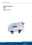
Mounting
Mount on a horizontal or vertical surface. While the RTV encapsulation protects its circuitry,
the PFB366 DB9 connector is not rated for NEMA4 / IP65 environments. Mount the gateway in
a suitable location or enclosure for your application. The gateway will generate up to 1.4W of
heat, so provide sufficient clearance and airflow to maintain 0°C to 70°C operating temperature
range. Use two screws (not provided) in the 0.19 inch mounting holes shown below to fasten the
PFB366 to the mounting surface.
MKS Instruments, Inc.
D.I.P. Products Group
5
PFB366 User Manual
revision 1.20
1.25
All dimensions
are inches
0.65
0.45
3.80
4.30
3.30
0.50
0.12
Mtg. Holes
(2) 0.19 DIA.
1.225
1.225
0.725
0.625 DIA. On Case Wall
0.70
0.542
1.10
Wiring
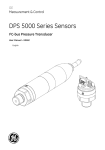
The PFB366 requires two connections – one to the Profibus-DP network (female DB9
connector) and one to the target serial device (male DB9 connector). Follow all applicable
electrical codes in your area when mounting and wiring any electrical device.
All power is received from an external 11-28VDC power supply connected to the serial channel
DB9 connector. The PFB366 draws up to 50mA from the power supply. Select your serial and
Profibus-DP cables and power supply so that it can provide sufficient current for all networked
devices at their peak operating power.
MKS Instruments, Inc.
D.I.P. Products Group
6
PFB366 User Manual
revision 1.20
Profibus-DP Interface
Female DB9 Profibus Connector
5
4
9
PIN
1
2
3
4
5
6
7
8
9
3
8
2
7
1
6
SIGNAL
NC
NC
B
RTS
GND
+5VDC
NC
A
NC
DESCRIPTION
No Connect. Do not connect any wires to NC pins.
No Connect.
Non-Inverting input/output communication signal from Profibus.
Profibus-DP Request-To-Send output signal (repeater control).
Isolated ground.
Isolated +5VDC supply.
No Connect.
Inverting input/output communication signal from Profibus.
No Connect.
Serial Channel Interface
Male DB9 Serial Connector
1
2
6
PIN
1
2
3
4
5
6
7
8
9
3
7
SIGNAL
NC
RXD
TXD
NC
GND
NC
RTS
CTS
NC
MKS Instruments, Inc.
4
8
5
9
DESCRIPTION
No Connect. Do not connect any wires to NC pins.
Receive Data. RS232 input signal.
Transmit Data. RS232 output signal.
No Connect.
Ground. Common for RS232 signals.
No Connect.
Request To Send. RS232 output signal.
Clear To Send. RS232 input signal.
No Connect.
D.I.P. Products Group
7
PFB366 User Manual
revision 1.20
Wiring Examples
The following are typical PFB366 gateway wiring configurations. Your RS232 or RS422/485
interface may vary. Refer to your device’s documentation for the required data and control
signals.
Simple RS232 Interface
RS232
Serial
Device
2 RXD
3 TXD
5 GND
RXD 2
TXD 3
GND 5
PFB366
+VCD 9
11-28VDC
Supply
8
3
4
6
5
A
B
RTS
+VDC
GND
RS232 Interface, HW Flow Control
RS232
Serial
Device
2
RXD
3
TXD
5 GND
7 RTS
8 CTS
RXD 2
TXD 3
GND 5
RTS
7
CTS
8
+VCD
PFB366
8
3
4
6
5
A
B
RTS
+VDC
GND
9
11-28VDC
Supply
MKS Instruments, Inc.
D.I.P. Products Group
8
PFB366 User Manual
revision 1.20
Chapter 3 – Theory of Operation
This chapter describes how the PFB366 gateway operates. You should have a working
knowledge of Profibus-DP and asynchronous serial communications before continuing. Refer to
your serial device documentation for its protocol information.
Gateway Operation
The PFB366 gateway receives asynchronous serial messages over its serial channel, converts
them to data values, and returns the values as input data to the Profibus master. The gateway
receives output data from the Profibus master, converts them into serial messages, and transmits
the messages out its serial channel. The following diagram shows the major gateway
components.
output data
DC:DC Power Conversion
• 11-28VDC power input
• VDC for Core & Serial channel
• isolated VDC for Profibus channel
Female DB9
connector
Male DB9
connector
Power
Gateway Core
• microcontroller
• RAM
• Flash ROM
input data
Profibus Channel
• Isolated 5VDC
• communications
Rotary Switches
Serial Transmit Process
Configures the Profibus
interface.
MKS Instruments, Inc.
Converts output data from
Profibus master into a
message packet. Transmits
message packet out the serial
channel.
Serial
messages
Serial Channel
• communications
• flow control
Serial Receive Process
Converts received message
packet to input data. Input
data returned to Profibus
master.
D.I.P. Products Group
Serial Stream Process
Configures the serial channel.
Scan channel for valid message
packets, which are passed to
Serial Receive Process.
9
PFB366 User Manual
revision 1.20
Profibus-DP Interface
The PFB366 gateway operates as a Profibus-DP slave. The Profibus master cyclically polls the
gateway, sending output data and reading input data.
The output and input data bytes are typically mapped into data files inside the Profibus-DP
master. These data files are exchanged with the user application program, which acts upon the
received input data and writes new output data to the Profibus master.
Input File
Inputs
input data
Receive
Message Packet
output data
Transmit
Message Packet
Outputs
Output File
Profibus
Master
Serial
Device
Application
Program
PFB366
Gateway
Profibus-DP network
The first 2 output data bytes received from the Profibus-DP master contain synchronization bits
for the gateway transmit and receive operations. The remaining output data bytes contain serial
message data to be transmitted out the serial channel.
Tx Synchronization Bytes
0
0
0
0
0
0
Rx Synchronization Bytes
Transmit Data Bytes
0
RA
0
0
0
TT
0
0
0
0
Bit 0 = Received Acknowledge bit
Bit 0 = Transmit Toggle bit
The first 2 input data bytes sent from the gateway contain synchronization bits for the gateway
transmit and receive operations. The remaining input data bytes contain serial message data that
has been received and processed by the gateway
Tx Synchronization Bytes
0
0
0
MKS Instruments, Inc.
0
0
0
Rx Synchronization Bytes
Receive Data Bytes
0
RT
0
0
TA
0
0
0
0
0
Bit 0 = Received Toggle bit
Bit 0 = Transmit Acknowledge bit
D.I.P. Products Group
10
PFB366 User Manual
revision 1.20
Serial Channel Interface
The PFB366 serial channel consists of an asynchronous serial transmitter and receiver. The
serial interface is configured and controlled by the Serial Stream Process parameters, Serial
Receive Process parameters, and Serial Transmit Process parameters.
Serial Stream Process
The Serial Stream Process parameters configure the serial channel’s baud rate, number of data
bits and stop bits, parity, and flow control. This configuration applies to both the serial
transmitter and receiver. The gateway has separate 255-byte serial transmit and receive FIFO
buffers, allowing full duplex operation when supported by the physical layer media.
The Serial Stream Process also scans incoming serial data for valid message packets. A message
packet is determined by one of three Delimiter modes. List mode searches for Pre-Delimiter and
Post-Delimiter byte strings at the beginning and end of a message. Length mode captures a
specific number of message bytes, defined by Packet Length. Timeout mode uses an inter-byte
delay (Packet Timeout) to signal the end of a message. When a message packet is received, it is
processed by all enabled Serial Receive Process. The following examples show the three Serial
Stream Process Delimiter modes.
Incoming data stream
0x45 0x62 0x02 0x31 0x32 0x32 0x42 0x45 0x03 0x0D 0x11 <delay> 0x43 0x56 …
0x02
0x31 0x32 0x32 0x42 0x45
Pre-Delimiter
Message Packet
List Mode (delimiters)
Length Mode (fixed #bytes)
Post-Delimiter
0x45 0x62 0x02 0x31 0x32 0x32 0x42 0x45
Message Packet
Packet Length = 8
Timeout Mode (inter-byte delay)
0x45 0x62 0x02 0x31 0x32 0x32 0x42 0x45 0x03 0x0D 0x11
Packet Timeout = 100 msec
MKS Instruments, Inc.
0x03 0x0D
D.I.P. Products Group
Message Packet
11
PFB366 User Manual
revision 1.20
Serial Receive Process
The Serial Receive Process processes the Message Packet bytes, converting them into an input
data value that is returned to the Profibus master. The Message Packet bytes can be converted
into a Short_String data type (byte array, with 1st byte = length). ASCII characters within the
Message Packet representing a numerical value can also be converted into signed or unsigned
integer or real number data types. The Serial Receive Process can be configured to search for
Pre-String and/or Post-String byte strings at the beginning and/or end of the desired data bytes.
The data bytes framed by the Pre-String and Post-String bytes are then converted into a
Short_String, integer, or real number. The following examples show how the Serial Receive
Process can be configured to process a Message Packet.
Received Message Packet
other bytes
Pre-String
Message Packet Bytes (ASCII)
Data
Post-String
other bytes
‘VALUE = 100 F’
1) Short_String
2) Short_String
3) Short_String
4) Integer (USINT)
data size = 14
Use Data Field
data size = 5
Use Data Field
data size = 4
Use Pre-String
Use Data Field
Use-Post-String
data size = 1
Use Pre-String
Use Data Field
Use-Post-String
13, ‘VALUE = 100 F’
4, ‘VALU’
MKS Instruments, Inc.
8, ‘VALUE = ‘
3, ‘100’
D.I.P. Products Group
2, ‘ F’
8, ‘VALUE = ‘
0x64
2, ‘ F’
12
PFB366 User Manual
revision 1.20
Serial Transmit Process
The Serial Transmit Process receives an output data value from the Profibus master. It converts
the output data into a serial message packet to transmit out the serial channel. The output data
format can be a Short_String (byte array, with 1st byte = length), a signed or unsigned integer, or
a real number data type. An integer or real number can be converted into ASCII characters that
represent the numerical value before it is transmitted. String1 and String2 character strings can
be placed before and/or after the converted data in the message packet, allowing you to build and
transmit complex messages. The following examples show how the Transmit Serial Process can
be configured to convert a data value into a message packet.
Parameter Message Packet
String1
String2
1) Output Data Bytes
0x03 0x41 0x42 0x43
Short_String, data size = 4.
Use Data Field.
[ 0x41 0x42 0x43 ] = ‘ABC’
Transmitted Message Packet
‘ABC’
Data
String1
String2
2) Output Data Byte
0x08
USINT integer, data size = 1,
width = 1, conversion = D.
Use Data Field.
[ 0x08 ] ‘8’ (0x38)
Transmitted Message Packet
3) Output Data Bytes
0xFF 0x47
INT integer, data size = 2,
width = 4, conversion = D.
Use String1 Before [ 0x06, ‘VAL = ‘].
Use Data Field.
Use String2 After [0x02, ‘ F’].
[ 0xFF 0x47 ] = -185 ‘-185’
‘8’
Transmitted Message Packet
‘VAL = -185 F’
MKS Instruments, Inc.
D.I.P. Products Group
13
PFB366 User Manual
revision 1.20
Asynchronous Serial Communictaion
Devices communicating on an asynchronous serial link exchange information one bit at a time.
Each bit is transmitted for a specific period of time, defined by the baud rate. Devices use
internal timing circuitry to measure the baud rate. There is no clocking signal between devices
to synchronize the serial data flow, hence the term asynchronous serial communications.
Serial data bits are organized into bytes. When a data byte is asynchronously transmitted, it is
preceded by a start bit, followed by the data bits, an optional parity bit, and one or more stop bits.
There can be a variable transmission delay between successive serial data bytes, since each byte
is framed by its own start and stop bits. The receiver starts saving serial bits after is receives a
valid start bit (0), and stops when it receives the expected number of stop bits (1). The data
byte’s least-significant bit is transmitted first (data bit 0), and the most-signficant bit is
transmitted last (data bit N).
[ start bit ] [ data bit 0 ] [ data bit 1 ] … [ data bit N ] [ optional parity bit ] [ stop bit(s) ]
The parity bit is used to detect single-bit errors in the transmission. The parity bit is
automatically calculated and inserted by the transmitter. The receiver calculates the parity of an
incoming byte, and compares it to the parity bit sent by the transmitter. If the two bit values do
not match, then at least one serial bit value was corrupted during transmission.
Flow control allows the receiving device to regulate the rate of incoming data. Hardware flow
control uses RTS/CTS signals between the devices to control the rate of transmission. Software
flow control uses serial characters XON/OFF to control the rate. Flow control helps protect
against lost data, if the receiving device cannot store incoming data fast enough, or if the
receiving device's buffer is full and cannot accept more data until it processes existing data.
Data Conversion
The PFB366 gateway can either pass through received serial message bytes to your application,
or pre-process an ASCII string into a numerical value. The gateway can transmit a string of
message bytes sent by the application, or it can convert a numerical value into an ASCII string to
be transmitted. Using the gateway’s data conversion feature offloads this cumbersome task from
your application program, especially if it is a PLC ladder-logic application. It also reduces the
required number of Profibus input and output bytes, since converted values instead of entire
message strings are transferred over Profibus.
The gateway conversion process supports the following data types:
Data Type
SINT signed 8-bit integer
INT
signed 16-bit integer
USINT unsigned 8-bit integer
UINT unsigned 16-bit integer
REAL 32-bit floating point
Short_String (byte array)
Data Size
1
2
1
2
4
2 to 26
Value Range
-128 to 127
-32768 to 32767
0 to 255
0 to 65535
+1.175E-38 to +3.4028E+38
string of bytes, 1st byte defines length
The Serial Transmit Process and Serial Receive Process parameters configure the conversion
process for transmitted and received messages. The Data Type parameter selects the desired data
MKS Instruments, Inc.
D.I.P. Products Group
14
PFB366 User Manual
revision 1.20
type for the Receive Data or Transmit Data value. The Data Size parameter represents the
number of bytes used by the selected data type. You must select the maximum data size
expected for your application if using the Short_String data type. The Short_String byte array
format is a length byte followed by data bytes, so you must add one to the expected number of
bytes. The table above defines the data size for all other data types.
The PFB366 gateway supports a maximum of 28 bytes for the Transmit Data value and 28 bytes
for the Receive Data value.
The Width parameter defines the number of ASCII bytes (1 to 16) used to represent a real or
integer number. For received messages, Width defines the number of ASCII bytes that will be
converted into a number. For transmitted messages, Width defines how many ASCII bytes will
be generated to represent the number. The Width value must include ASCII sign (+/-), exponent
(E), and decimal point (.) characters. Width is not used for Short_String data types.
The Precision parameter is only used for transmitted messages. It defines the number of digits
(1 to 6) after the decimal point for a floating-point number. The gateway will automatically add
trailing zeros to the converted number if needed. Precision is only used for the REAL data type.
The following examples show how to calculate the Data Size, Width, and Precision parameters
for the different Data Types. Remember to add a length byte to the Short_String Data Size.
Data Type
SINT
INT
USINT
UINT
REAL
REAL
Short_String
ASCII chars
‘-12’
‘-12345’
‘123’
‘1234’
‘1.23E+4’
‘-1.1234E-12’
‘ABCDEF’
Data Size
1
2
1
2
4
4
7 (length=6)
Width
3
6
3
4
7
11
not used
Precision
not used
not used
not used
not used
2
4
not used
The Conversion parameter is different for Serial Receive Process and Serial Transmit Process.
For the Serial Receive Process, the Conversion parameter denotes if the ASCII bytes represent a
decimal integer or a hexadecimal integer. If decimal is selected, then the gateway converts the
ASCII bytes as a decimal number. If hexadecimal is selected, then the gateway converts the
ASCII bytes as a hex number.
‘1234’ If decimal, integer = 1234.
‘1234’ If hexadecimal (0x1234), integer = 4660.
For the Serial Transmit Process, the Conversion parameter also denotes if the ASCII bytes
represent a decimal or hexadecimal integer. If decimal is selected, then the gateway converts the
integer into a decimal ASCII representation. If hexadecimal is selected, then the gateway
converts the integer into a hex ASCII representation.
Integer = 1234 If decimal, ASCII representation = ‘1234’
Integer = 1234 If hexadecimal, ASCII representation = ‘04D2’
MKS Instruments, Inc.
D.I.P. Products Group
15
PFB366 User Manual
revision 1.20
The Serial Transmit Process Conversion parameter can also be used to insert leading zeros into a
converted number. If the ASCII representation of a number contains fewer characters than the
selected Width, then leading zeros can added in front of the number.
Integer = 1234, Width = 7 If leading zeros enabled, ASCII representation = ‘0001234’
Integer = 1234, Width = 7 If leading zeros disabled, ASCII representation = ‘1234’
The following examples show a variety of different gateway data conversions for received and
transmitted data values.
Example 1 – Data Type = Short_String, Data Size = 9
Received ASCII data is ‘12345678’. The Serial Receive Process parameter coverts this to 9 bytes of Receive Data,
[0x08, 0x31, 0x32, 0x33, 0x34, 0x35, 0x36, 0x37, 0x38] or [0x08, ‘12345678’]. The first byte defines the
Short_String length as 8 bytes.
Example 2 – Data Type = Short_String, Data Size = 5
Received ASCII data is ‘12345678’. The Serial Receive Process Parameter converts this to 4 bytes of Receive Data,
[0x04, 0x31, 0x32, 0x33, 0x34] or [0x04, ‘1234’]. The first byte defines the Short_String length as 4 bytes. With
Data Size = 5, only the first 4 data bytes are used.
Example 3 – Data Type = Short_String, Data Size = 12
Received ASCII data is ‘ABCDEFGH’. The Serial Receive Process Parameter converts this to 9 bytes of Receive
Data, [0x08, 0x41, 0x42, 0x43, 0x44, 0x45, 0x46, 0x47, 0x48] or [0x08, ‘ABCDEFGH’]. The first byte defines the
Short_String length as 8 bytes. Even though Data Size = 12, only the 8 received bytes are returned.
Example 4 – Data Type = SINT, Width = 5, Conversion = Hex
Received ASCII data is ‘18’. The Serial Receive Process Parameter converts this to 1 byte of Receive Data, [0x18].
Example 5 – Data Type = INT, Width = 4, Conversion = Decimal
Received ASCII data is ‘-25’. The Serial Receive Process Parameter converts this to 2 bytes of Receive Data, [0xFF
0xE7]. The ASCII ‘-25’ decimal number converts to 0xFFE7.
Example 6 – Data Type = REAL, Width = 13
Received ASCII data is ‘-1.2345E-16’. The Serial Receive Process Parameter converts this to 4 bytes of Receive
Data, [0xNN, 0xNN, 0xNN, 0xNN]. This is the 32-bit floating-point representation for ‘–1.2345E-16’.
Example 7 – Data Type = REAL, Width = 7
Received ASCII data is ‘-1.2345E-16’. The Serial Receive Process Parameter converts this to 4 bytes of Receive
Data, [0xNN, 0xNN, 0xNN, 0xNN]. This is the 32-bit floating-point representation for ‘-1.2345’. With Width = 7,
only the first 7 ASCII bytes are converted.
Example 8 – Data Type = Short_String, Data Size = 8
Transmit Data is [0x08, 0x31, 0x32, 0x33, 0x34, 0x35, 0x36, 0x37, 0x38]. The Serial Transmit Process Parameter
converts this into 8 ASCII bytes ‘12345678’. Note the first Transmit Data byte defines the Short_String length in
bytes. This length byte is not transmitted.
Example 9 – Data Type = SINT, Width = 5, Conversion = Hex, Leading Zeros
Transmit Data is [0x18]. The Serial Transmit Process Parameter converts this into 5 ASCII bytes ‘00018’. Leading
zeros are added to match the Width = 5.
Example 10 – Data Type = INT, Width = 6, Conversion = Decimal, No Leading Zeros
Transmit Data is [0xFF 0xE7]. The Serial Transmit Process Parameter converts this into the ASCII string
MKS Instruments, Inc.
D.I.P. Products Group
16
PFB366 User Manual
revision 1.20
‘-25’. The Width is 3 bytes greater than ‘-25’, but leading zeros are not selected.
Example 11 – Data Type = REAL, Width = 13, Precision = 6, Conversion = No Leading Zeros
Transmit Data is [0xNN 0xNN 0xNN 0xNN], representing the real number –1.2345E-16. The Serial Transmit
Process Parameter converts this into the ASCII string ‘-1.234500E-16’. The Precision is 2 bytes greater than
needed, so trailing zeros are added after the decimal point.
Serial Receive Example
The following example shows how the PFB366 gateway captures a serial message packet,
processes the packet, converts the data into a number, and returns it as a Profibus input value.
The gateway’s Serial Stream Process is configured for the List delimiter mode, with a one-byte
Pre-Delimiter string and a two-byte Post-Delimiter string. An incoming message must have
matching delimiter strings to be accepted as a valid message packet.
The Serial Receive Process has the Use Pre-String, Use Data, and Use Post-String options
selected for its Receive Mode. The message packet must have matching Pre-String and PostString values before the data is processed. The Data Type is configured for SINT, with a Width
of 2 and Conversion set for decimal. The data field’s two-byte ASCII string represents a decimal
number, which is converts into an 8-bit signed integer. The converted number is saved as the
new Receive Data value. The gateway also toggles its Receive Toggle bit to signal the reception
of new data.
When the gateway is polled for input data, it returns the Transmit Acknowledge byte, Receive
Toggle byte, and Receive Data byte(s). The Transmit Acknowledge bit is mapped to bit 0 in the
first byte. The Receive Toggle bit is mapped to bit 0 of the second byte. The Receive Data value
makes up the rest of the input bytes. The Profibus master passes these input bytes for the
application program.
The user application receives the updated gateway inputs. Program logic recognizes the state
change in the Receive Toggle bit, indicating that gateway has sent new input data. To
acknowledge that it has read the new data, the user application toggles the Receive Acknowledge
bit, which gets sent back to the gateway by the Profibus master. When the Serial Receive
Process gets the updated Receive Acknowledge bit, it can then process the next incoming serial
message.
MKS Instruments, Inc.
D.I.P. Products Group
17
PFB366 User Manual
revision 1.20
Serial Receive Process
Serial
Device
STX ‘TEMP = 64 C’ CR ETX
PFB366
Gateway
INPUT DATA BYTES
Profibus
Master
OUTPUT DATA BYTES
1) Serial Device transmits message.
Serial Data (ASCII)
Serial Data (hex)
<STX> T
E
M
P <SP> = <SP> 6
4 <SP> C <CR> <ETX>
0x02 0x54 0x45 0x4D 0x50 0x20 0x3D 0x20 0x36 0x34 0x20 0x43 0x0D 0x03
2) Serial Stream Process receives message
and loads into rx buffer without delimiters.
Delimiter Mode = List
Pre-Delimiter = [ 0x01 0x02 ]
Post-Delimiter = [ 0x02 0x0D 0x03 ]
0x54 0x45 0x4D 0x50 0x20 0x3D 0x20 0x36 0x34 0x20 0x43
3) Serial Receive Process processes message
packet.
Pre-String = [ 0x07, ‘TEMP = ’ ]
Data = [ ‘64’ ]
Post-String = [ 0x02, ‘ C’ ]
0x54 0x45 0x4D 0x50 0x20 0x3D 0x20
4) ASCII data to Data Type value.
Data Type = SINT, Width = 2, Conversion = D
0x36 0x34 ⇒ ‘64’⇒ 64 decimal ⇒ 0x40 hex
5) Receive Data value sent to Profibus master.
PROFBUS INPUT DATA BYTES
TA = Transmit Acknowledge byte
RT = Receive Toggle bits ( bit0 toggled 0-1)
0x40 = Receive Data
6) Application acknowledges reading new Receive Data.
PROFIBUS OUTPUT DATA BYTES
TT = Transmit Toggle byte
RA = Receive Acknowledge byte ( bit 0 set to 1)
MKS Instruments, Inc.
D.I.P. Products Group
0x36 0x34 0x20 0x43
0x36 0x34
0x40
TA RT=xxxxxxx1 0x40
TT RA=xxxxxxx1 Tx Data
18
PFB366 User Manual
revision 1.20
Serial Transmit Example
The following example shows how the PFB366 gateway receives Profibus output data, converts
the data into an ASCII string, then builds and transmits a serial message using the converted
string.
The gateway receives new output data from the Profibus master. The first output byte contains
the Transmit Toggle bit (bit 0). The second byte contains the Receive Acknowledge bit (bit 0).
The remaining data bytes are the Transmit Data value. In this example, Serial Transmit Process
receives a toggled Transmit Toggle bit, indicating the application has sent a new Transmit Data
value to the output bytes.
Serial Transmit Process is configured for SINT Data Type, with Width of 2 and Conversion set
for decimal with no leading zeros. It converts its new Transmit Data value 0x52 into the ASCII
string ‘82’. The Transmit Mode parameter is set for String1 Before, Data, and String2 After.
The resulting serial message that gets loaded into the gateway transmit buffer consists of
[String1, ‘82’, String2]. The message will be sent when the serial channel transmitter is
available.
When the new message is loaded in the transmit buffer, the gateway toggles its Transmit
Acknowledge bit, indicating that is it ready to receive the next Transmit Data value. The updated
Transmit Acknowledge bit is read by the application as an input byte. There may have been
subsequent Profibus read/write cycles in between the time the gateway received the new
Transmit Data value and the time it toggles its Transmit Acknowledge bit.
Serial Transmit Process
Serial
Device
STX ‘SET T = 82 C’ CR ETX
1) Transmit Data received from Profibus master.
PROFIBUS OUTPUT BYTES
TT = Transmit Toggle byte (bit 0 toggled 0-1)
RA = Receive Acknowledge byte (bit 0)
0x52 = Transmit Data
PFB366
Gateway
PROFIBUS INPUT BYTES
PROFIBUS OUTPUT BYTES
TT=00000001 RA 0x52
2) Serial Transmit Processconverts data to ASCII.
Data Type = SINT, Width = 2, Conversion = D
0x52 hex 82 decimal ‘82’ or [ 0x38 0x32 ]
0x52
0x38 0x32
3) Builds message & loads into transmit buffer.
String1 = [0x09 0x02 ‘SET T = ‘] 0x02 0x53 0x45 0x54 0x20 0x54 0x20 0x3D 0x20
Data = [ ‘82’ ]
String2 = [0x04 ‘ C’ 0x0D 0x03]
4) Gateway transmits message.
Serial Data Stream (hex bytes)
Serial Data Stream (ASCII)
MKS Instruments, Inc.
Profibus
Master
0x38 0x32 0x20 0x43 0x0D 0x03
0x02 0x53 0x45 0x54 0x20 0x54 0x20 0x3D 0x20 0x38 0x32 0x20 0x43 0x0D 0x03
<STX> S
E
T <SP> T <SP> = <SP> 8
2 <SP> C <CR> <ETX>
D.I.P. Products Group
19
PFB366 User Manual
revision 1.20
Synchronization
There are four independent processes operating in a PFB366 gateway application. The first
process is the exchange of input and output data between the user application program and the
Profibus master. The second process is the exchange of input and output data between the
gateway and Profibus master, using read and write over Profibus. The third process is receiving
serial messages and converting it to input data. The fourth process is converting output data and
transmitting it as serial messages. To ensure that no information is lost between the gateway’s
serial channel and the user application program, the PFB366 incorporates a receive
synchronization feature and a transmit synchronization feature.
I/O Exchange between
Profibus Master and
Application
Input File
I/O Exchange between
PFB366 gateway and
Profibus Master
Convert serial message
into Input Data
Inputs
input data
Receive
Message Packet
Convert Output Data
into serial message
Outputs
Output File
output data
Profibus
Master
Transmit
Message Packet
Serial
Device
Application
Program
PFB366
Gateway
Profibus network
Receive Synchronization
The gateway receive synchronization feature is optional for Serial Receive Process. It is enabled
by the Sync Enable parameter. When enabled, the gateway will not process a new message
packet until the last Receive Data value has been read and acknowledged by the application
program. When a Serial Receive Process updates its Receive Data value, it also toggles its
Receive Toggle bit to indicate a new data value is available. The user application monitors the
Receive Toggle bit, and reads the Receive Data value when the bit changes state. Once the
application has read and processed or stored the new Receive Data value, it acknowledges
receipt by setting the Receive Acknowledge bit equal to the Receive Toggle bit. The gateway is
now able to start processing the next serial message packet. The Receive Toggle and Receive
Acknowledge bits are set to 0 at power-up.
The Receive Acknowledge bit maps to bit 0 in the second byte of the Profibus output data. The
Receive Toggle bit maps to bit 0 in the second byte of the Profibus input data. This bit mapping
MKS Instruments, Inc.
D.I.P. Products Group
20
PFB366 User Manual
revision 1.20
makes it easy for ladder-logic applications to implement the gateway’s receive-synchronization
process. The following 2 ladder-logic rungs show how an application program can monitor for
the gateway’s Receive Toggle bit, copy the new Receive Data value to save it, and set the
Receive Acknowledge bit equal to the Receive Toggle bit
|
bit = 1
bit = 0
|
|------[ RX Toggle ]-------[ /RX Ack ]--------------------|------------( copy RX Data to variable )--------|
|
|
|
|
|--------------------( RX Ack )---------------------|
|
bit =1
|
|
bit = 0
bit = 1
|
|------[ /RX Toggle ]------[ RX Ack ]---------------------|------------( copy RX Data to variable )--------|
|
|
|
|
|--------------------( /RX Ack )--------------------|
|
bit =0
|
Transmit Synchronization
The gateway transmit synchronization is always enabled Serial Transmit Process. The gateway
will not process its Transmit Data output bytes until its Transmit Toggle bit changes state. When
the user application sends new Transmit Data to the gateway, it must toggle the Transmit Toggle
bit. This enables the gateway to process the new output value and load the resulting serial
message into the transmit buffer. When the message is loaded for transmission, the gateway
acknowledges transmission by setting its Transmit Acknowledge bit equal to the Transmit Toggle
bit. The application can now send the next Transmit Data value. The Transmit Toggle and
Transmit Acknowledge bits are set to 0 at power-up.
The Transmit Toggle bits maps to bit 0 in the first byte of the Profibus output bytes. The
Transmit Acknowledge bit maps to bit 0 in the first byte of Profibus input bytes. This bit
mapping makes it easy for ladder-logic applications to implement transmit synchronization. The
following 2 ladder-logic rungs show how an application program writes the gateway’s Transmit
Data value, toggles the Transmit Toggle bit, and waits for the Transmit Acknowledge bit to equal
the Transmit Toggle bit before writing the next Transmit Data value.
|
bit = 0
bit = 0
|
|------[ /TX Toggle ]-------[ /TX Ack ]-------------------|-----------( copy variable to TX Data )---------|
|
|
|
|
|--------------------( TX Toggle )-----------------|
|
bit =1
|
|
bit = 1
bit = 1
|
|------[ TX Toggle ]-------[ TX Ack ]--------------------|------------( copy variable to TX Data )--------|
|
|
|
|
|--------------------( /TX Toggle )----------------|
|
bit =0
|
MKS Instruments, Inc.
D.I.P. Products Group
21
PFB366 User Manual
revision 1.20
Chapter 4 – Gateway Configuration
This chapter describes how to configure and operate the PFB366 gateway. You configure the
gateway by reading and writing parameter values over its Profibus interface. There are a variety
of Profibus configuration tools available. You can configure the gateway using the user interface
defined in the gateway’s GSD file.
Configure Profibus Interface
Set the Profibus Address using the rotary switches. Configure switches before connecting to the
Profibus network. There is either a small triangular indicator or white indicator on the switch.
Use a small screwdriver to align that indicator with the desired setting. Remove the PFB366
cover if necessary to access the rotary switches.
Node Address Switches
The two Node Address switches represent decimal numbers from 0x00 to 0xFF. The LSB
switch selects the lower 4 bits (lower nibble) and the MSB switch selects the upper 4 bits (upper
nibble) of the 8-bit hexadecimal address. Valid Node Addresses are 0x00 to 0x7D (0-125).
Setting a Node Address greater than 0x7D forces the gateway to use the Node Address saved in
retentive memory from previous power cycle. A valid Node Address must first be saved in the
gateway before this feature can be used.
MSB
0
1
2
3
4
5
6
7
7
LSB
0 to F
0 to F
0 to F
0 to F
0 to F
0 to F
0 to F
0 to D
E,F
Address
00 to 15
16 to 31
32 to 47
48 to 63
64 to 79
80 to 95
96 to 111
112 to 125
stored address
MSB
8
9
A
B
C
D
E
F
LSB
0 to F
0 to F
0 to F
0 to F
0 to F
0 to F
0 to F
0 to F
Address
stored address
stored address
stored address
stored address
stored address
stored address
stored address
stored address
Power Up Gateway
Connect the gateway to a Profibus network and apply power to the gateway.
Gateway Status LEDs
The PFB366 gateway has two bi-color status LEDs (NET and MOD) that indicate operational
status. During power-up, the LEDs cycle through a sequence of alternating red and green. After
power-up, the NET and MOD LEDs will be solid green if the slave has recognized the Profibus
baud rate and entered its data exchange mode. If this does not occur, power down and verify all
the switch settings, or proceed to download the database of PFB366 parameters.
MKS Instruments, Inc.
D.I.P. Products Group
22
PFB366 User Manual
revision 1.20
State
Off
Flashing Red
Solid Red
Flashing Green
Solid Green
Profibus Status LED (NET)
Wait Parameter/Configuration State.
Not Used.
Not Used.
Wait Parameter/Configuration State.
Data Exchange (Normal runtime operation.)
State
Off
Flashing Red
Solid Red
Flashing Green
Solid Green
Module Status LED (MOD)
No power.
Not Used.
Baud Search State. Auto-baud for Profibus baud rate.
Not Used.
Baud Rate Found. Normal Operation.
Serial Channel Status LEDs
The gateway has two bi-color LEDs to indicate serial channel activity. The TX LED flashes
green when a packet is being transmitted. The RX LED flashes green when a packet is being
received. A fault is indicated by solid red. After power-up, both LEDs should be off.
State
Off
Flashing Red
Solid Red
Flashing Green
Solid Green
Transmit Status LED (TX)
No data being transmitted
Not defined
Transmit error (parity or overrun error)
Data being transmitted
Not defined
State
Off
Flashing Red
Solid Red
Flashing Green
Solid Green
Receive Status LED (RX)
No data being received
Not defined
Receive error (parity or overrun error)
Data being received
Not defined
Register GSD File
If using a Profibus configuration tool that supports GSD files, you should now register the
gateway’s GSD file with the software. The latest GSD file versions can be downloaded from
www.mksinst.com. Select the GSD file that matches your gateway’s part number and firmware
version. Follow your configuration tool instructions to register GSD file.
MKS Instruments, Inc.
D.I.P. Products Group
23
PFB366 User Manual
revision 1.20
Configure Serial Channel
The Serial Stream Process parameters control the physical layer settings for the PFB366 serial
channel. These settings apply to all serial transmit and receive operations. The parameters also
configure the reception of message packets. Before you can set or change any gateway
configuration settings, make sure the gateway is not on line with the Profibus master.
Serial Stream Process Parameter Parameters (Parameter Group 64, Parameter Device 1)
Number
Name
Data Type
Value
3
Baud Rate
UDINT
300, 1200, 2400, 4800, 9600, 19200 bps
4
Data Bits
USINT
7, 8
5
Parity
USINT
0 = no parity
1 = odd parity
2 = even parity
3 = mark
4 = space
6
Stop Bits
USINT
1, 2
7
Flow Control
USINT
0 = none
1 = XON / XOFF
2 = CTS / RTS
10
Delimiter Mode
USINT
Bit 0 – List mode
Bit 1 – Timeout mode
Bit 2 – Length mode
11
Pre-Delimiter List Short_String List mode – String of 1-9 bytes.
12
Post-Delimiter List Short_String List mode – String of 1-9 bytes.
13
Packet Timeout
USINT
Timeout mode – delay between received bytes (1-255 msec).
14
Packet Length
USINT
Length mode – Number of message bytes (1-255).
Baud Rate – Sets the serial channel’s data or baud rate. Enter Baud Rate in bits-per-second
(bps) as a decimal number.
Data Bits – Selects the number of data bits in one serial byte. This number does not include
start, parity, or stop bits.
Parity – Selects the parity type used in the serial byte. Selecting any parity option other than
NONE adds 1 parity bit to the serial byte length.
Stop Bits – Selects the number of stop bits in one serial byte.
Flow Control – Selects the method of flow control used across the serial interface.
NONE means there is no flow control over the serial data exchange. The transmitting device can
overflow the receiving device’s buffer.
XON/XOFF is a software flow control option. Receiving device sends an XOFF character to the
transmitting device when its buffer is full, stopping further transmission. It sends an XON
character when it can again receive data. The XOFF and XON characters are not saved as
message data.
MKS Instruments, Inc.
D.I.P. Products Group
24
PFB366 User Manual
revision 1.20
CTS/RTS is an RS232 hardware flow control option, available only on the PFB366 gateway. The
RTS is an output and CTS is an input signal. The gateway keeps RTS active (low) when it can
receive data. It only transmits data when CTS is active (low).
Delimiter Mode – Defines how the gateway determines when it has received a message packet.
The three delimiter modes are List, Timeout, and Length. Setting the appropriate bit in the
Delimiter Mode byte selects the respective mode. The Delimiter Mode byte defines bits 0, 1, 2
only. Set the remaining bits 3 through 7 to zero.
List mode is used when a message packet is framed by a specific strings of Pre-Delimiter and
Post-Delimiter bytes. The Pre-Delimiter signals the start of a new packet. The Post-Delimiter
indicates the end of the packet. Each Pre-Delimiter and Post-Delimiter string can be from 1 to 9
bytes in length. When the gateway receives the Pre-Delimiter string, it saves the subsequent
data bytes until the Post-Delimiter string is received. The Pre-Delimiter and Post-Delimiter
bytes are not saved in the message packet. The following is a simple ASCII message example.
Pre-Delimiter
[STX]
Message Packet
Post-Delimiter
[data1] [data2] … [dataN]
[ETX] [CR]
Length mode is used when every message packet contains the same number of bytes. The
Packet Length parameter defines the packet size, from 1 to 255 bytes. The gateway saves serial
bytes until it receives the specified number, and saves them as one message packet.
Timeout mode uses a delay between received data bytes to determine the end of a message
packet. The Packet Timeout parameter defines the time-out period, from 1 to 255 milliseconds.
Pre-Delimiter List – Required for List Mode. Enter a string of 1 to 9 bytes that defines the start
of a new serial message. Use Short_String data format, with 1st byte = string length. Example
Pre-Delimiter is [ 0x01 0x02 ], where string length is 1 and delimiter character is 0x02 (STX).
Post-Delimiter List – Required for List Mode. Enter a string of 1 to 9 bytes that defines the end
of a serial message. Use Short_String data format, with 1st byte = string length. Example PostDelimiter is [ 0x02 0x0D 0x03 ], where string length is 2 and delimiter characters are 0x0D (CR)
and 0x03 (ETX).
Packet Timeout – Required for Timeout Mode. Defines the timeout period between received
bytes that indicates the end of a message packet (1-255 milliseconds).
Packet Length – Required for Length Mode. Defines the message packet size (1-255 bytes).
MKS Instruments, Inc.
D.I.P. Products Group
25
PFB366 User Manual
revision 1.20
Serial Receive Process Settings
This section describes how to configure the Serial Receive Process.
Serial Receive Process Parameters (Parameter Group 65, Parameter Device 1)
Name
Data Type
Value
Number
6
Receive Mode
USINT
Bit 0 – use Data Field
Bit 1 – use Pre-String Field
Bit 2 – use Post-String Field
7
Pre-String
Short_String String of 1-9 bytes.
8
Post-String
Short_String String of 1-9 bytes.
9
Data Type
USINT
194 (0xC2) = SINT (1 byte)
195 (0xC3) = INT (2 bytes)
198 (0xC6) = USINT (1 byte)
199 (0xC7) = UINT (2 bytes)
202 (0xCA) = REAL (4 bytes)
218 (0xDA) = Short String (Data Size bytes)
10
Data Size
USINT
1-26
11
Width
USINT
1-16
13
Conversion
USINT
‘D’ (0x44) = decimal integer.
‘X’ (0x58) = hexadecimal integer.
14
Pad Char
CHAR
Pad byte value. Pad Poll Response if Rx data does not fill up Poll
response message data.
17
Sync Enabled
BOOL
0 = disabled, 1 = enabled
Receive Mode – Defines how the gateway processes message packet bytes. The gateway can
search for 3 fields – Pre-String, Data, and Post-String. Set associated bits (0, 1, 2) to use the
desired fields. Set the remaining bits 3 through 7 to zero.
[ Pre-String ] [ Data ] [ Post-String ]
Pre-String parameter defines the byte string for the Pre-String field. Data Size parameter
defines the number of bytes expected in the Data field. Post-String parameter defines the byte
string for the Post-String field.
When Use Pre-String bit is set, the gateway searches the message packet bytes for a match to the
stored Pre-String. If a match is not found, the message packet is ignored.
When Use Data bit is set, the gateway converts the Data Size number of message bytes into a
value defined by Data Type, and saves it as Receive Data. If there are not enough message
bytes, the message packet is ignored. You must select Use Data in order to send input data to the
Profibus master.
When Use Post-String bit is set, the gateway searches the message packet bytes for a match to
the stored Post-String. If a match is not found, the message packet is ignored.
MKS Instruments, Inc.
D.I.P. Products Group
26
PFB366 User Manual
revision 1.20
Pre-String – Required if Use Pre-String selected in Receive Mode. Enter a string of 1-9 bytes in
Short_String data format, with 1st byte = string length. Example Pre-String is [ 0x01 0x41 ],
where string length is 1 and pre-string character is 0x41 (‘A’)
Post-String – Required if Use Post-String selected in Receive Mode. Enter a string of 1-9 bytes
in Short_String data format, with 1st byte = string length. Example Post-String is [ 0x02 0x42
0x43 ], where string length is 2 and post-string characters are 0x42 (‘B’) and 0x43 (‘C’)
Data Type – The gateway converts received ASCII message data into the selected data type for
Receive Data.
Decimal
Hex.
Data Type
Date Size (byte)
Value Range
194
195
0xC2
0xC3
SINT (signed 8-bit integer)
INT (signed 16-bit integer)
1
2
-128 ~ 127
-32768 ~ 32767
198
0xC6
USINT (unsigned 8-bit integer)
1
0 ~ 255
199
202
218
0xC7
0xCA
0xDA
UINT (unsigned 16-bit integer)
REAL (32-bit floating point value)
Short_String
2
0 ~ 65535
+1.175E-38 ~ +3.4028E+38
4
Set by data size attribute, Max. 26 bytes
Enter number from decimal (or hex) column to select the desired data type. Data Size column
defines the number of data bytes for Receive Data. For Short_String, set Data Size parameter to
the desired number of data bytes (plus 1 length byte). Set the Width parameter to the expected
number of ASCII bytes to be converted into a real or integer number.
Data Size – Required for Short_String Data Type. Defines the maximum number of bytes in a
Short-String, plus one length byte (2-26). The first byte in a Short_String defines the string
length.
The Data Size parameter for Serial Receive Process and Serial Transmit Process must sum to a
total less than or equal to 64 bytes, regardless of whether the process is being used. Set unused
process’s Data Type parameter to USINT or SINT, which have 1-byte Data Size.
Width – Required for SINT, INT, USINT, UINT, REAL Data Types. Defines the number of
ASCII bytes (1-16) to be converted into an integer or real number.
Conversion – Required for SINT, INT, USINT, UINT Data Types. Denotes if the ASCII bytes
represent a decimal integer (‘D’ or 0x44) or a hexadecimal integer (‘X’ or 0x58).
Pad Char – Byte value to pad the RX Message bytes.
Sync Enabled – Enables receive synchronization with the user application. When enabled, the
gateway will not update its Receive Data until the Receive Acknowledge bit matches the Receive
Toggle bit. Enabling receive synchronization ensures that the user application does not miss any
received message data between polls.
MKS Instruments, Inc.
D.I.P. Products Group
27
PFB366 User Manual
revision 1.20
Serial Transmit Process Settings
This section describes how to configure the Serial Transmit Process.
Serial Transmit Process Parameters (Parameter Group 66, Parameter Device 1)
Number
Name
Data Type
Value
6
Transmit Mode
USINT
Bit 0 – use Data
Bit 1 – use String1 before data
Bit 2 – use String2 before data
Bit 3 – use String1 after data
Bit 4 – use String2 after data
7
String1
Short_String String of 1-9 bytes.
8
String2
Short_String String of 1-9 bytes.
9
Data Type
USINT
194 (0xC2) = SINT (1 byte)
195 (0xC3) = INT (2 bytes)
198 (0xC6) = USINT (1 byte)
199 (0xC7) = UINT (2 bytes)
202 (0xCA) = REAL (4 bytes)
218 (0xDA) = Short String (Data Size bytes)
10
Data Size
USINT
1-26
11
Width
USINT
1-16
12
Precision
USINT
0-6
13
Conversion
USINT
Bit 0 – hex (0 for decimal, 1 for hex)
Bit 7 – use leading zeros to pad number
Transmit Mode – Defines the message packet structure to be transmitted. The message packet
can consist of 5 fields – String1 Before, String2 Before, Data, String1 After, and String2 After.
Set associated bits (0, 1, 2, 3, 4) to enable the desired fields. Set the remaining bits 5-7 to zero.
[ String1 Before ] [ String2 Before ] [ Data ] [ String1 After ] [ String2 After ]
String1 parameter defines the byte string for the String1 Before and String1 After fields. Data
Size parameter defines the number of bytes expected in the Data field. String2 parameter defines
the byte string for the String2 Before and String2 After fields. While the Data field is typically
selected, you can configure the gateway to transmit a predefined message using String1 and/or
String2, without requiring any output data bytes from the Profibus master.
When the String1 Before and/or String2 Before bits are set, the gateway places the respective
byte string(s) at the beginning of the message packet. If both options are selected, String1 is
placed before String2. The gateway then loads the converted data bytes in the Data field. If the
String1 After and/or String2 After bits are set, the Parameter places the respective byte string(s)
at the end of the message packet. If both options are selected, then String1 is placed before
String2. The message packet is then loaded into the Transmit Buffer to be sent out the serial
channel.
MKS Instruments, Inc.
D.I.P. Products Group
28
PFB366 User Manual
revision 1.20
String1 – Required if String1 Before or String1 After selected in Transmit Mode. Enter a string
of 1-9 bytes in Short_String data format, with 1st byte = string length. Example String1 is [ 0x02
0x41 0x42 ], where string length is 2 and post-string characters are 0x41 (‘A’) and 0x42 (‘B’).
String2 – Required if String2 Before or String2 After selected in Transmit Mode. Enter a string
of 1-9 bytes in Short_String data format, with 1st byte = string length. Example String2 is [ 0x03
0x43 0x44 0x45 ], where string length is 3 and post-string characters are 0x43 (‘C’), 0x44 (‘D’),
and 0x45 (‘E’).
Data Type – Defines the Transmit Data parameter data type.
Decimal
Hex.
Data Type
Date Size (byte)
Value Range
194
195
0xC2
0xC3
SINT (signed 8-bit integer)
INT (signed 16-bit integer)
1
2
-128 ~ 127
-32768 ~ 32767
198
0xC6
USINT (unsigned 8-bit integer)
1
0 ~ 255
199
202
218
0xC7
0xCA
0xDA
UINT (unsigned 16-bit integer)
REAL (32-bit floating point value)
Short_String
2
0 ~ 65535
+1.175E-38 ~ +3.4028E+38
4
Set by data size parameter Max. 26 bytes
Enter number from decimal (or hex) column to select the desired data type. Data Size column
defines the number of data bytes for Transmit Data. For Short_String, set Data Size parameter
to the desired number of data bytes (plus 1 length byte). Set the Width parameter to the expected
number of ASCII bytes to be converted into a real or integer number. Set the Precision
parameter to the desired number of digits after the decimal point in a real number.
Data Size – Required for Short_String Data Type. Defines the maximum number of bytes in a
Short-String, plus one length byte (2-26). The first byte in a Short_String defines the string
length
The Data Size parameters for Serial Receive Process and Serial Transmit Process must sum to a
total less than or equal to 64 bytes, regardless of whether the process is being used. Set unused
process’ Data Type parameters to USINT or SINT, which have a 1-byte Data Size.
Width – Required for SINT, INT, USINT, UINT, REAL Data Types. Defines the number of
ASCII bytes (1-16) that will represent the integer or real number.
Precision – Required for REAL Data Type. Defines the number of digits (0 to 6) after the real
number decimal point. Gateway adds trailing zeros to the converted value if needed.
Conversion – Selects Leading Zeros and Hex or Decimal representation. The following are
valid options for the Conversion byte.
bit 7
0
0
1
1
bit 0
0
1
0
1
MKS Instruments, Inc.
decimal
0
1
128
129
hex
0x00
0x01
0x80
0x81
description
no leading zeros, decimal integer
no leading zeros, hexadecimal integer
leading zeros, decimal integer
leading zeros, hexadecimal integer
D.I.P. Products Group
29
PFB366 User Manual
revision 1.20
When bit 0 = 0, the ASCII bytes represent the Transmit Data integer number in a decimal
format. When bit 0 = 1, the ASCII bytes represent the integer number in a hexadecimal format.
This bit only applies to SINT, INT, USINT, and UINT Data Types.
When bit 7 = 1, leading zeros are added to real and integer numbers as needed to match the
Width setting. This bit only applies to SINT, INT, USINT, UINT, and REAL Data Types.
MKS Instruments, Inc.
D.I.P. Products Group
30
PFB366 User Manual
revision 1.20
Configure Profibus Master
You must calculate the number of input and output bytes required by your PFB366 configuration
before you configure the Profibus master. You need to configure the Profibus master to send the
specific number of output bytes, and receive the specific number of input bytes from the
gateway. Once the input and output bytes are mapped in the Profibus master, the user
application program will be able to read and write data values to the input and output bytes.
Three (3) or four (4) Profibus master configuration bytes specify the presence and size of the
gateway’s input and output data. Use 3 configuration bytes if the gateway is only used for
receiving or transmitting messages. Use 4 configuration bytes if the gateway is used to both
receive and transmit messages.
Connfig Byte 1
Config Byte 2
Config Byte 3
Config Byte 4
Configuration byte 1 defines the first 2 input and output bytes, used for the gateway’s transmit
and receive synchronization process. Its value is 0x31 (49).
0x31
The second configuration byte defines the remaining gateway input and output data bytes. This
special ID byte declares the presence of Receive Data input and/or Transmit Data output bytes.
Enter 0xC0 (192) to use both Receive Data input bytes and Transmit Data output bytes. Enter
0x80 (128) to use Transmit Data output bytes only (no input data bytes). Enter 0x40 (64) to use
Receive Data input bytes only (no output data bytes)
The third and fourth configuration bytes define the required number of Receive Data and
Transmit Data bytes. The number of bytes specified in the configuration must be one less than
the corresponding value’s Data Size. For example, if the Receive Data consists of 4 input bytes,
enter 3 as the Receive Size. If the Transmit Data consists of 2 output bytes, enter 1 as the
Transmit Size. When using both Receive Data and Transmit Data, each value’s size is specified
in the third and fourth configuration.
Use Input & Output Data Bytes
0x31
0xC0
Receive Size
Use Output Data Bytes Only
0x31
0x80
Transmit Size
Use Input Data Bytes Only
0x31
0x40
Receive Size
MKS Instruments, Inc.
D.I.P. Products Group
Transmit Size
31
PFB366 User Manual
revision 1.20
Chapter 5 – Configuration Examples
This chapter contains four gateway configuration examples.
Example 1 – Receiving Data
Read UPC labels into a PLC using a serial barcode scanner, a PFB366 gateway, and a Profibus
master. The barcode scanner RS232 channel is connected to a PFB366 serial channel. The
PFB366 Profibus channel is connected to the PLC Profibus master.
Barcode Scanner
PLC & Profibus Master
PFB366
Gateway
UPC labels
RS232
Profibus network
Barcode Scanner
The barcode scanner’s RS232 channel is set for 9600 bps, 8 data bits, no parity, and 1 stop bit.
When it reads a UPC label, it transmits the following ASCII message format. The message
always begins with the ASCII STX start-of-text (0x02) character, and always ends with the
ASCII ETX end-of-text (0x03) and CR carriage return (0x0D) characters. The barcode data will
consist of a variable number of 1 to 12 ASCII characters, depending upon the UPC label being
scanned.
[ STX ] [ ASCII barcode data ] [ ETX ] [ CR ]
PFB366 Gateway
The PFB366 gateway needs to be configured to receive this RS232 message format. The first
step is to determine the Delimiter Mode. The barcode scanner transmits a variable-length
message packet, so Length Mode cannot be used. Timeout Mode may be used, but without
specific timing information for the barcode scanner’s RS232 channel it may be difficult to derive
a suitable Packet Timeout value. List Mode is best suited for this application, because the serial
message always begins and ends with the same characters. The Serial Stream Process can now
be configured. The following shows the Serial Stream Process parameter settings for this
application. The 3rd column lists the parameter group/device/number/value. The last two
parameters are Short_String data types.
Serial Stream Process Configuration (Parameter Group 64, Device 1)
Parameter
3. Baud Rate
4. Data Bits
5. Parity
6. Stop Bits
7. Flow Control
10. Delimiter Mode
11. Pre-Delimiter String
12. Post-Delimiter String
Data
9600
8
0
1
2
1
0x01 0x02
0x02 0x03 0x0D
MKS Instruments, Inc.
Parameter Group/Device/Number /Value
0x40 0x01 0x03 0x25 0x80
0x40 0x01 0x04 0x08
0x40 0x01 0x05 0x00
0x40 0x01 0x06 0x01
0x40 0x01 0x07 0x02
0x40 0x01 0x0A 0x01
0x40 0x01 0x0B 0x01 0x02
0x40 0x01 0x0C 0x02 0x03 0x0D
D.I.P. Products Group
Description
9600 bps
8 data bits
no parity
1 stop bit
CTS / RTS
List Mode
Short_String length = 1, STX
Short_String length = 2, ETX CR
32
PFB366 User Manual
revision 1.20
The next step is to configure the PFB366 gateway to return the ASCII barcode data to the
Profibus master. Because the content of the ASCII bytes is not known, the entire byte string will
be converted into a Short_String data type. The Data Type is Short_String, with a Data Size of
13 (maximum number of expected barcode data bytes is 12, plus the length byte). The Receive
Mode is Use Data Field.
Serial Receive Process Parameters Configuration (Parameter Group 65, Device 1)
Parameter
6. Receive Mode
9. Data Type
10. Data Size
Data
1
218
13
Parameter Group/Device/Number/Value
0x41 0x01 0x06 0x01
0x41 0x01 0x09 0xDA
0x41 0x01 0x0A 0x0D
Description
Use Data Field
Short_String
1 length byte, 12 data bytes
The gateway will return 15 input bytes to the Profibus master. The input bytes are organized as
follows:
[ Transmit Acknowledge bits ] [ Receive Toggle bits ] [ Receive Data (Short_String)]
1 byte
1 byte
13 bytes
The gateway will always return 13 of Receive Data, even if the scanned barcode data contains
fewer bytes. The application should check the Short_String length byte to determine the number
of valid data bytes being returned.
Receive synchronization may also be used by enabling the Sync Enabled parameter.
MKS Instruments, Inc.
D.I.P. Products Group
33
PFB366 User Manual
revision 1.20
Example 2 – Receiving Delimited Data
Using the same configuration as Example 1, the scanned UPC labels are printed in the following
formats: [ MODEL xxx A ]. The ‘xxx’ are 3 ASCII characters that represent a number from 1
to 100. The gateway is configured to read this specific UPC label format, convert the ASCII
characters into integer, and return them as Profibus input data.
Barcode Scanner
The barcode scanner’s RS232 channel is set for 9600 bps, 8 data bits, no parity, and 1 stop bit.
When it reads a UPC label, it transmits the following ASCII message format. The message
always begins with the ASCII STX start-of-text (0x02) character, and always ends with the
ASCII ETX end-of-text (0x03) and CR carriage return (0x0D) characters. The barcode data will
consist of a variable number of ASCII characters, depending upon the UPC label being scanned.
[ STX ] [ ‘MODEL xxx A’ ] [ ETX ] [ CR ]
14 bytes ASCII data
PFB366 Gateway
The PFB366 gateway needs to be configured to receive this RS232 message format. The first
step is to determine the Delimiter Mode. The barcode scanner still transmits a variable length
message, so Length Mode cannot be used. Timeout Mode may be used, but without specific
timing information for the barcode scanner’s RS232 channel it may be difficult to derive a
suitable Packet Timeout value. List Mode is best suited for this application, because the serial
message always begins and ends with the same characters. The Serial Stream Process can now
be configured. The following shows the Serial Stream Process parameter settings for this
application. The 3rd column lists the parameter group/device/number/value. The last two
parameters are Short_String data types.
Serial Stream Process Configuration (Parameter Group 64, Device 1)
Parameter
3. Baud Rate
4. Data Bits
5. Parity
6. Stop Bits
7. Flow Control
10. Delimiter Mode
11. Pre-Delimiter String
12. Post-Delimiter String
Data
9600
8
0
1
2
1
0x01 0x02
0x02 0x03 0x0D
Parameter Group/Device/Number/Value
0x40 0x01 0x03 0x25 0x80
0x40 0x01 0x04 0x08
0x40 0x01 0x05 0x00
0x40 0x01 0x06 0x01
0x40 0x01 0x07 0x02
0x40 0x01 0x0A 0x01
0x40 0x01 0x0B 0x01 0x02
0x40 0x01 0x0C 0x02 0x03 0x0D
Description
9600 bps
8 data bits
no parity
1 stop bit
CTS / RTS
List Mode
Short_String length = 1, STX
Short_String length = 2, ETX CR
The next step is to configure the PFB366 gateway to process the label formats and convert the
ASCII characters into integer numbers, to be returned as a Profibus input.
Serial Receive Process is configured to process the 11-character model number UPC label
message packet. The Receive Mode is set to Use Pre-String, Use Data, and Use Post-String
fields. The Pre-String parameter is set to ‘MODEL ‘, and Post-String is set to ‘ A’ (space and
character ‘A’). These two strings are used to filter for the model-number message packet. The
model number range is 1 to 100, so the Data Type is set for USINT with a Width of 3, and
Conversion is set to decimal. The Data Size is 1 byte for USINT.
MKS Instruments, Inc.
D.I.P. Products Group
34
PFB366 User Manual
revision 1.20
Serial Receive Process Parameter Configuration (Parameter Group 65, Device 1)
Parameter
6. Receive Mode
7. Pre-String
Data
7
0x06, ‘MODEL ‘
8. Post-String *
9. Data Type
11. Width
13. Conversion
0x02, ‘ A’
198
3
‘D’
Parameter Group/Device/Number/Value
0x41 0x01 0x06 0x07
0x41 0x01 0x07 0x06 0x4D 0x4F 0x44 0x45
0x4C 0x20
0x41 0x01 0x08 0x02 0x20 0x41
0x41 0x01 0x09 0xC6
0x41 0x01 0x0B 0x03
0x41 0x01 0x0D 0x44
Description
use Data, Pre-String, Post-String fields
Short_String length = 6, ‘MODEL ‘
Short_String length = 2, ‘ A’
USINT (8-bit unsigned integer)
3 ASCII bytes to be converted
ASCII bytes represent decimal number
*Note: The post string consists of a space character and character A.
The gateway returns 3 input bytes to the Profibus master. The data is organized as follows:
[ Transmit Acknowledge bits ] [ Receive Toggle bits ] [ Receive Data (USINT)]
1 byte
1 byte
1 byte
The gateway is now configured to receive the barcode message packets, convert the embedded
number into either an 8-bit unsigned integer number, and return it as Profibus input byte.
Receive synchronization may also be used by enabling the Sync Enabled parameter.
MKS Instruments, Inc.
D.I.P. Products Group
35
PFB366 User Manual
revision 1.20
Example 3 – Transmitting Data
Print an ASCII string from a PLC to a serial printer, using a PFB366 gateway and a Profibus
master. The text message string can be from 1 to 25 characters long, including any ASCII
control characters. The serial printer RS232 channel is connected to a PFB366 serial channel.
The PFB366 Profibus channel is connected to the PLC Profibus master.
PLC & Profibus Master
PFB366
Gateway
Serial Printer
RS232
Profibus network
Serial Printer
The serial printer’s RS232 channel is set for 300 bps, 7 data bits, even parity, and 2 stop bits. It
uses XON / XOFF software flow control.
PFB366 Gateway
The PFB366 serial channel is configured to transmit this RS232 message format. The Serial
Stream Process parameters are shown below for this application. The 3rd column lists the
parameter group/device/number.
Serial Stream Process Configuration (Parameter Group 64, Device 1)
Parameter
3. Baud Rate
4. Data Bits
5. Parity
6. Stop Bits
7. Flow Control
Data
300
7
2
2
1
Parameter Group/Device/Number/Value
0x40 0x01 0x03 0x01 0x2C
0x40 0x01 0x04 0x07
0x40 0x01 0x05 0x02
0x40 0x01 0x06 0x02
0x40 0x01 0x07 0x01
Description
300 bps
7 data bits
Even parity
2 stop bit
XON / XOFF
The next step is to configure the PFB366 gateway to transmit data received from the Profibusmaster to the serial printer. To allow the printing of any text message, the gateway is configured
to pass through the ASCII data bytes from the Profibus master to the printer. The gateway will
receive a Short_String variable from the Profibus master. The Data Type is Short_String, with a
Data Size of 26 (maximum text message size is 25, plus the length byte). The Transmit Mode is
Use Data.
Serial Transmit Process Configuration (Parameter Group 66, Device 1)
Parameter
6. Transmit Mode
9. Data Type
10. Data Size
Data
1
218
26
Parameter Group/Device/Number/Value
0x42 0x01 0x06 0x01
0x42 0x01 0x09 0xDA
0x42 0x01 0x0A 0x1A
Description
Use Data
Short_String
1 length byte, 26 data bytes
The gateway expects to receive 28 output bytes from the Profibus master, with the data
organized as follows:
[ Transmit Toggle bits 0 ] [ Receive Acknowledge bit 0] [Transmit Data (Short_String)]
1 byte
1 byte
26 bytes
MKS Instruments, Inc.
D.I.P. Products Group
36
PFB366 User Manual
revision 1.20
The gateway is now configured to receive ASCII text messages up to 25 characters in length and
send them to the serial printer. The Profibus master will always send 28 output bytes to the
gateway, even if the text message is shorter than 25 characters. The gateway uses the
Short_String length byte to determine the number of valid characters to be transmitted.
Transmit synchronization must be used by the application. The application toggles the Transmit
Toggle bit in the first output byte, and monitors the Transmit Acknowledge bit in the first input
byte. When the Transmit Acknowledge bit equals the Transmit Toggle bit, then the application
can send the next text message.
MKS Instruments, Inc.
D.I.P. Products Group
37
PFB366 User Manual
revision 1.20
Example 4 – Transmitting Delimited Data
Using the same configuration as Example 3, the PFB366 gateway is configured to print a predefined text messages and inserting an integer value into a message.
‘TEMP = xxx C, xxx F’, <CR>, <LF>
(xxx is value, range of –50 to +400)
Serial Printer
The serial printer’s RS232 channel is set for 300 bps, 7 data bits, even parity, and 2 stop bits. It
uses XON / XOFF software flow control.
PFB366 Gateway
The PFB366 gateway is configured to transmit this RS232 message format. The Serial Stream
Process parameters are shown below for this application. The 3rd column lists the parameter
group/device/number/value
Serial Stream Process Configuration (Parameter Group 64, Device 1)
Parameter
3. Baud Rate
4. Data Bits
5. Parity
6. Stop Bits
7. Flow Control
Data
300
7
2
2
1
Parameter Group/Device/Number/Value
0x40 0x01 0x03 0x01 0x2C
0x40 0x01 0x04 0x07
0x40 0x01 0x05 0x02
0x40 0x01 0x06 0x02
0x40 0x01 0x07 0x01
Description
300 bps
7 data bits
Even parity
2 stop bit
XON / XOFF
The next step is to configure the PFB366 gateway to transmit the specific message.
Serial Transmit Process is configured to transmit the message. It receives an integer value from
the Profibus master, converts it to 3 ASCII characters, builds a message packet, and transmits it.
The Transmit Mode is Use String1 Before Data, Use Data, and Use String2 After Data. String1
is [‘TEMP = ‘]. String2 is [‘ C, ’]. The Data Type is INT, to cover the –50 to 400 range. The
Width is 3, and the Conversion is set for decimal with no leading zeros.
Serial Transmit Process Configuration (Parameter Group 66, Device 1)
Parameter
6. Transmit Mode
Data
19
Parameter Group/Device/Number/Value
0x42 0x01 0x06 0x13
7. String1
0x07, ‘TEMP = ‘
8. String2
9. Data Type
11. Width
13. Conversion
0x04, ‘ C, ’ CR LF
195
3
1
0x42 0x01 0x07 0x07 0x54 0x45 0x4D 0x50
0x20 0x3D 0x20
0x42 0x01 0x08 0x04 0x20 0x43 0x0D 0x0A
0x42 0x01 0x09 0xC3
0x42 0x01 0x0B 0x03
0x42 0x01 0x0D 0x01
Description
Use Data, String1 Before, String2
After
Short String length = 7, ‘TEMP = ‘
Short String length = 4, ‘ C, ’ CR LF
INT (16-bit signed integer)
convert to 3 ASCII bytes
represent integer in decimal
The gateway expects to receive 3 output bytes from the Profibus master with the data organized
as follows:
[ TX Toggle (bit 0)] [ RX Acknowledge (bit 0)] [ Transmit Data (UINT)]
1 byte
1 byte
1 byte
Transmit synchronization must be used. The application toggles the Transmit Toggle bit when it
sends new temperature values, and monitors Transmit Acknowledge bit to tell when the message
has been sent.
MKS Instruments, Inc.
D.I.P. Products Group
38
PFB366 User Manual
revision 1.20
Chapter 6 – Troubleshooting
Problem
Profibus Configuration Program
does not recognize Gateway.
•
Possible Cause
Register Gateway GSD file with Configuration Program.
Profibus Configuration Program
does not recognize Gateway after
loading GSD file.
•
Check Major and Minor Revisions for Gateway and GSD file, to see if you have
correct GSD file for your Gateway's firmware version.
Gateway does not appear on
Profibus network.
•
•
•
•
•
Check wiring and cable connections.
Check gateway power supply voltage.
Make sure Gateway baud rate matches network baud rate.
Verify Gateway Node Address is set from rotary switches or retentive memory.
Make sure Gateway Node Address is not used by another device.
After setting Gateway Node
•
Address, Profibus Master does not •
recognize Gateway.
•
Disconnect Gateway from network before changing Node Address.
Make sure Gateway NODE ADDRESS is not used by another device.
Verify Gateway NODE ADDRESS is set from rotary switches or retentive
memory value.
Verify gateway supports Profibus baud rate.
Gateway is in Wait Parameter/Configuration State. Download PFB366
parameters using Profibus Configuration Tool.
NET LED is off or flashing green.
•
•
MOD LED is off.
•
Gateway is not powered. Check power supply and cable connection.
MOD LED is solid red
•
Gateway is searching for Profibus baud rate. Make sure Profibus netword is
configured to baud rate supported by gateway.
RX LED does not flash green when •
data is sent to the Gateway.
•
If Sync Enabled, make sure Receive Toggle and Receive Acknowledge bits are
being toggled. If application does not toggle Receive Acknowledge, Gateway
will not receive data.
Verify source device is transmitting data to Gateway.
RX LED is solid red after Gateway •
receives data.
•
Check extended diagnostics byte for RX buffer Overflow or parity Error. Reset
gateway to clear errors.
Make sure parity is set to match transmitting device.
TX LED is solid red after receiving •
data from Profibus Master.
•
Check extended diagnostic byte for TX buffer Overflow or Parity Error. Reset
Gateway or clear Serial Status error bit if necessary.
Make sure parity is set to match transmitting device.
TX LED does not flash green when •
Gateway should be transmitting
data.
If Sync Enabled, make sure Transmit Toggle is being toggled. If application
does not toggle Transmit Toggle, Gateway will not transmit data.
MKS Instruments, Inc.
D.I.P. Products Group
39
PFB366 User Manual
revision 1.20
The slave contains diagnostic data showing the current state and any error that may have
occurred. Among the first six bytes is the station status, shich displays the status and any fault of
the slave, including: if watchdog, freeze mode, and sync mode are enabled, extended or static
diagnostic exist, the slave is activated, or any parameter/configuration fault occurred. For
example, if Serial Receive/Transmit LEDs turn solid red, check the extended diagnostics
message to determine what type of error occurred. The length of error message is shown in the
seventh byte and the actual error data begins at the eight byte.
Slave Single Diagnostic
Station
Status 1
Station
Status 2
Station
Status 3
Master
Address
Indent
…
…
Number
Length
of Ext
Diag
Extended
Diagnostics
Extended Diagnostic Byte
Bit 7
Reserved
Bit 6
Bit 5
Bit 4
Reserved Reserved
Error 3
Bit 3
Bit 2
Reserved Reserved
Bit1
Bit 0
Error 2
Error 1
Error 1: Serial Receive FIFO Overrun – buffer filled beyond maximum capability.
Error 2: Serial Receive Parity Error
Error 3: Serial Transmit FIFO overrun – buffer filled beyond maximum capability
MKS Instruments, Inc.
D.I.P. Products Group
40
PFB366 User Manual
revision 1.20
Appendix A – Product Specifications
Profibus Interface
Isolation:
Reverse Polarity:
Signal Levels:
Supported Baud Rates:
500 Volts
-30 Vdc
RS485
9600, 19.2K, 93.75K, 187.5K, 500K, 1.5M, 3M
(auto baud)
Serial Channel
Power Requirements:
ESD Protection:
Overload Protection:
Short Circuit:
RS232 Output Levels:
11 - 28 Vdc @ 50 mA
+/- 10 kV
+/- 30 Volts
Indefinite
+/- 7.9 Volts (unloaded, typical)
Environmental
Operating Temperature:
Storage Temperature:
Size (inches):
Mounting (inches)
PCB Encapsulation:
0o C to 70o C
-25o C to 85o C
3.25 x 2.37 x 1.08
0.5 tabs, 3/16 diameter mounting holes
RTV Silicon Compound
MKS Instruments, Inc.
D.I.P. Products Group
41
PFB366 User Manual
revision 1.20
Appendix B – Profibus Parameter Template
Group
Device
Number
MKS Instruments, Inc.
Default
Setting
Unit
D.I.P. Products Group
Comments
42
PFB366 User Manual
revision 1.20
Appendix C – ASCII Character Codes
Non-Printable Characters
Printable Characters
Hex
Dec
Char
Name
Kybd Hex
0x00
0x01
0x02
0x03
0x04
0x05
0x06
0x07
0x08
0x09
0x0A
0x0B
0x0C
0x0D
0x0E
0x0F
0x10
0x11
0x12
0x13
0x14
0x15
0x16
0x17
0x18
0x19
0x1A
0x1B
0x1C
0x1D
0x1E
0x1F
0
1
2
3
4
5
6
7
8
9
10
11
12
13
14
15
16
17
18
19
20
21
22
23
24
25
26
27
28
29
30
31
NUL
SOH
STX
ETX
EOT
ENQ
ACK
BEL
BS
HT
LF
VT
FF
CR
SO
SI
DLE
DC1
DC2
DC3
DC4
NAK
SYN
ETB
CAN
EM
SUB
ESC
FS
GS
RS
US
Null
Start of heading
Start of text
End of text
End of transmit
Enquiry
Acknowledge
Bell
Backspace
Horizontal tab
Line feed
Vertical tab
Form feed
Carriage return
Shift out
Shift in
Data line escape
Device control 1
Device control 2
Device control 3
Device control 4
Negative acknowledge
Synchronous idle
End of transmit block
Cancel
End of medium
Substitute
Escape
File separator
Group separator
Record separator
Unit separator
Ctrl @
Ctrl A
Ctrl B
Ctrl C
Ctrl D
Ctrl E
Ctrl F
Ctrl G
Ctrl H
Ctrl I
Ctrl J
Ctrl K
Ctrl L
Ctrl M
Ctrl N
Ctrl O
Ctrl P
Ctrl Q
Ctrl R
Ctrl S
Ctrl T
Ctrl U
Ctrl V
Ctrl W
Ctrl X
Ctrl Y
Ctrl Z
Ctrl [
Ctrl \
Ctrl ]
Ctrl ^
Ctrl _
MKS Instruments, Inc.
0x20
0x21
0x22
0x23
0x24
0x25
0x26
0x27
0x28
0x29
0x2A
0x2B
0x2C
0x2D
0x2E
0x2F
0x30
0x31
0x32
0x33
0x34
0x35
0x36
0x37
0x38
0x39
0x3A
0x3B
0x3C
0x3D
0x3E
0x3F
Dec
32
33
34
35
36
37
38
39
40
41
42
43
44
45
46
47
48
49
50
51
52
53
53
55
56
57
58
59
60
61
62
63
Char
Space
!
"
#
$
%
&
'
(
)
*
+
,
.
/
0
1
2
3
4
5
6
7
8
9
:
;
<
=
>
?
D.I.P. Products Group
Hex
0x40
0x41
0x42
0x43
0x44
0x45
0x46
0x47
0x48
0x49
0x4A
0x4B
0x4C
0x4D
0x4E
0x4F
0x50
0x51
0x52
0x53
0x54
0x55
0x56
0x57
0x58
0x59
0x5A
0x5B
0x5C
0x5D
0x5E
0x5F
Dec
64
65
66
67
68
69
70
71
72
73
74
75
76
77
78
79
80
81
82
83
84
85
86
87
88
89
90
91
92
93
94
95
Char
@
A
B
C
D
E
F
G
H
I
J
K
L
M
N
O
P
Q
R
S
T
U
V
W
X
Y
Z
[
\
]
^
_
Hex
0x60
0x61
0x62
0x63
0x64
0x65
0x66
0x67
0x68
0x69
0x6A
0x6B
0x6C
0x6D
0x6E
0x6F
0x70
0x71
0x72
0x73
0x74
0x75
0x76
0x77
0x78
0x79
0x7A
0x7B
0x7C
0x7D
0x7E
0x7F
Dec
96
97
98
99
100
101
102
103
104
105
106
107
108
109
110
111
112
113
114
115
116
117
118
119
120
121
122
123
124
125
126
127
Char
`
a
b
c
d
e
f
g
h
i
j
k
l
m
n
o
p
q
r
s
t
u
v
w
x
y
z
{
|
}
~
DEL
43