1
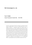
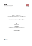
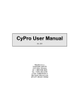
IPU User Manual
rev. 9
(applies to IPU IEX mode v1.4/PLC mode v2.3/CyPro 2.3.4 and later)
© 2006,2007 Cybrotech Ltd
Cybrotech Ltd
14 Brinell Way, Harfreys Industrial Estate
Great Yarmouth, Norfolk, Nr31 OLU - UK
tel: +44 1493 650 222
www.cybrotech.co.uk
[email protected]
General description
General description
IPU (Inverter Programming Unit) is a PLC for integration with Hitachi SJ300/L300P inverter.
It has:
- 8 digital inputs
- 8 digital outputs
- 4 analog inputs
- 1 analog output
- IEX-2 (CAN) port
- serial communication to inverter
IPU is placed into inverter option slot:
IEX-2 port may be used for connecting:
- CyBro-2
- operator panel
- other IPU-s
External, fully programmable operator panel is available.
A020-fre q ue n c y se ttin g
Cur rent:25.0Hz (0-40Hz )
Using IPU, inverters are capable of performing tasks not possible before, such as time-controlled operation or
group-synchronize operation. Some application examples are listed here:
Parameter access
Access to selected application-specific parameters, with optional
password protection.
Dosator machine
Precise dosator using hose-pump control and internal counter.
Enhanced multi-stage
Multi-stage with control logic and programmable timers.
Fail-safe pump station
Using intelligent monitoring, failure may be detected, allowing pumpstation to continue normal operation.
Equalizing operating hours
Using intelligent power-management control, inverters take care that load
is evenly distributed among pumps, providing longer pump life and longer
service period.
Regulation with sleep-mode
If frequency is below predefined level, IPU may automatically put inverter
into sleep mode.
1
Operation modes
Operation modes
IPU may operate in two different modes:
1) PLC mode
IPU is a stand-alone controller, programmed according to application.
IPU
Operator panel
IPU
Programming is made in C, adding application logic to ready-made template. Input/output and communication
are handled by the template. User has to put application-specific code into "iex_app.c" module and compile
the project.
KEIL C compiler
FLIP
IPU
iex.c
template project
app.hex
IPU
iex_app.c
application-specific code
Program is loaded to IPU using ISP-adapter and FLIP software. For more details about loading, please check
"ISP programming.pdf".
2) IEX-2 mode
IPU is CyBro-2 external i/o module. Program logic is implemented in CyBro, IPU is used to access inverter
parameters.
CyBro-2
I/O modules
IPU
IPU
2
PLC mode example
PLC mode example
Demo application is an example of multi-speed operation.
Four setting frequencies may be edited by operating panel.
f4
f3
f2
f1
Predefined parameters:
A001=2 (frequency source to keypad)
A002=2 (run command source to keypad)
F002=500 (acceleration time to 5s)
F003=500 (deceleration time to 5s)
Parameters are sent immediately after power-on.
Panel preview:
multispeed
frequency 2
multispeed
frequency 1
multispeed
frequency 4
multispeed
frequency 3
5 10 15 25 Hz
+--+--+--+-- 10
progress
bar
current
frequency
Command keys:
set
value
next
frequency
start/stop
3
PLC mode programming reference
PLC mode programming reference
input/output
---------------bit ix0..ix7 - digital inputs, 0-off, 1-on
bit qx0..qx7 - digital outputs, 0-off, 1-on
uchar iw0..iw3 - 8-bit analog inputs, 0-0V, 255-10V
uchar qw0 - 8-bit analog output, 0-0V, 255-10V
bit RUNSWITCH - run/stop switch, 0-stop (on), 1-run (off)
bit RUNLED - run LED, 0-on, 1-off
inverter parameters
-------------------------struct ip[0..15] - input parameters
struct qp[0..15] - output parameters
ip/qp fields
-------------uint address - parameter address
uchar size - parameter size in bytes (1..4)
uint value - parameter value
uchar event - request to read/write parameter from/to inverter
For input parameters, event should be set to desired read period:
0 - never
1 - every 1000ms
2 - every 100ms
3 - every 10ms
For output parameters, event is used as request to send parameter:
128 - request to send (defined as WRITE_PENDING)
timers
-------bit timer_10ms;
bit timer_100ms;
bit timer_1000ms;
Used by user application to perform time-synchronized tasks.
Bits are set by system at predefined intervals, and should be cleared by user application.
functions
-----------bit _testbit_(bit x) - read bit and clear, return 1 if x is 1, set x to 0
operating panel
--------------------uchar disp_buf[32] - display buffer, starting from up left corner
bit refresh_display_req - request to send buffer to panel (set automatically for print functions)
bit key_up,key_dn,key_e,key_f - current state of panel keys
bit send_empty_mask - used for panel initialization
uchar mask_data_count - used for panel initialization
void at(uchar x, y) - set cursor position
void print_string(char code *p) - print an ascii string on cursor position
void print_integer(long v, uchar n, uchar d, uchar zb) - print a long integer on cursor position
(v-value, n-places, d-decimals, zb-zero blanking)
4
IEX-2 mode operation
IEX-2 mode operation
Before reading or writing inverter parameters, IPU should be configured. Configuration is a process of
selecting parameters which will be used during the normal operation.
Two separate configuration areas are available, ip for reading and qp for writing parameters.
Both areas are divided into four blocks, which are sent and received independently. Each block contains four
variables (ip00-ip03, ip04-ip07, ip08-ip11, ip12-ip15, qp16-qp19, qp20-qp23, qp24-qp27, qp28-qp31). Each
variable may be configured separately (address and size). 3 or 4-byte inverter value is received in two
variables.
Input variables should also have specified reading frequency (event). Event should be zero for output
variables.
After configuration, read variables will be updated periodically. To write a parameter, write value into variable
and set the request bit.
5
IEX-2 mode examples
IEX-2 mode examples
1. Reading current inverter frequency
Parameter:
Address:
Size:
Update:
D001
$400
4 bytes
100ms
Configuration:
if first_scan then
ipu00_config_index:=0; // read to ip00
ipu00_config_address:=1024;
ipu00_config_size:=4;
ipu00_config_event:=2; // 100ms interval
ipu00_config_req:=1; // send configuration
end_if;
Normal operation:
current_frequency:=65536*word(ipu00_ip00)+word(ipu00_ip01);
2. Run/stop inverter
Parameter:
Address:
Size:
Update:
A020
$472
1 byte
on request
Configuration:
if first_scan then
ipu00_config_index:=16; // write from qp16
ipu00_config_address:=1138;
ipu00_config_size:=1;
ipu00_config_event:=0; // ignored
ipu00_config_req:=1; // send configuration
end_if;
Normal operation:
ipu00_qp16:=1; // run
ipu00_qp16_req:=1; // request to send
Please also check "IPUDemo.cyp" from CyPro Examples directory.
6
Technical specifications
Technical specifications
Picture below summarizes IPU inputs, outputs and communication channels:
IX (digital inputs)
Input type
Debounce
Update time
24V, typ. 7mA, sink or source (PNP or NPN), opto isolated
10ms software filter, common for all inputs
10ms (IEX-2 mode)
QX (digital outputs)
Output type
Load
Update time
N-channel V-FET (current source, load to ground), opto isolated
1A/30V DC
100ms (IEX-2 mode)
IW (analog inputs)
Input type
Input resistance
A/D converter
Conversion time
Update time
Accuracy
0..10V
10kohm
8-bit succesive approximation register
100us
100ms (IEX-2 mode)
2% of FSR at 25°C
QW (analog output)
Output type
Output current
D/A converter
Settling time
Update time
Accuracy
0..10V
max. 10mA
8-bit resistor-string DAC, guaranteed monotonic
100us
100ms (IEX-2 mode)
2% of FSR at 25°C
Galvanic isolation
CAN bus is galvanically separated from CPU and main inverter body, but it is connected to inverter 24V power
output (common to inverter digital inputs).
7
Wiring examples
Wiring examples
Connect IPU outputs to inverter inputs (common minus):
24VDC
L300P inverter
common
P24
PLC
24V
0V
Input circuits
CM1
1
2
3
4
5
QX0 QX1 QX2 QX3 QX4
IPU
Output circuits
Connect inverter outputs to IPU inputs (common minus):
24VDC
L300P inverter
Relay outputs
P24
PLC
CM1
CI
12C
12A
11C
IX0
IPU
common
11A
IX1
Input circuits
Connect inverter outputs to IPU inputs (common plus):
L300P inverter
24VDC
Relay outputs
P24
CI
PLC
CM1
12C
IPU
common
12A
11C
IX0
11A
IX1
Input circuits
8
Order options
Order options
IPU-Pxx-EM
IPU module with preloaded software:
IPU-P00-EM - IEX-2 mode system software
IPU-P01-EM - PLC mode multi-speed demo (source available)
OP-2i
Operator panel for IPU.
ISP ADAPTER
Kit for loading predefined programs to IPU. It contains:
- ISP adapter
- FLIP software
PC with MS Windows 2000 (or later) and COM port is needed.
IPU STARTER PACK
Kit for writing new PLC-mode applications. It contains:
- IPU-P01-EM module
- OP-2i operator panel
- 2m cable
- PLC mode template and demo (C/asm source code)
- ISP adapter
- FLIP software
- cupon for a free one-day training, valid for one person
Kit does not include programming software. Any C51 compiler
may be used, but for full compatibility with extensions used in
template, KEIL C is suggested (www.keil.com).
9
Appendix
Appendix
Address range:
Memory area
External RAM
Internal RAM
EEPROM buffer area
RAM monitor area
Inverter status area
IPU address
0000 - 03FF
0400 - 3FF0
4000 - 4FFF
Inverter address
0800 0000 - 0800 03FF
0800 0400 - 0800 3FF0
FFFF 8000 - FFFF 8FFF
Short overview of frequently used SJ300/L300P parameters:
Identifier
Address
Size
Decimal
places
Range
Default
Unit
Access
Name
Control
A020
$0000
4
2
0..40000
0
Hz
Read/write
RunStop
$0472
1
0
0, 1, 2, 4
0
Multispeed
Frequency 0
Run command for
operater
Monitoring
D001
D002
D003
D004
D005
$0400
$042C
$044A
$0404
$042E
4
2
1
4
2
3
1
0
2
0
0..400000
0..10000
0..2
0..999900
0..65535
D006
$0446
2
0
0..65535
D007
D013
D014
$0408
$0448
$0432
2
2
2
0
1
1
0..65535
0..10000
0..10000
V
kW
D016
D017
TripCnt
$0410
$0414
$0360
4
4
2
0
0
0
0..232-1
0..232-1
s
s
Configuration (standard)
A001
$023F
1
A002
$0240
1
1
1
0..5
1..5
1
1
A021
$000C
4
2
0..40000
0
Hz
Read/write
A022
$0010
4
2
0..40000
0
Hz
Read/write
A023
$0014
4
2
0..40000
0
Hz
Read/write
A071
C001
$0260
$0299
1
1
0
0
0..1
1..255
0
18
Read/write
Read/write
C002
$029A
1
0
1..255
16
Read/write
C011
$02A1
1
0
0..1
0
Read/write
C012
$02A2
1
0
0..1
0
Read/write
F002
F003
$0058
$0064
4
4
2
2
1..360000
1..360000
3000
3000
s
s
Read/write
Read/write
Frequency source
Run command
source
Multispeed
frequency 1
Multispeed
frequency 2
Multispeed
frequency 3
PID Enable
Function of input
terminal 1
Function of input
terminal 2
Condition of input
terminal 1
Condition of input
terminal 2
Acceleration time
Deceleration time
0
0
30..400
0..15
50
0
Hz
Read/write2
Read/write2
Maximum frequency
EEPROM store flag
Configuration (actionprocess1)
A004
$00F8
2
EE store
$044B
1
Read/write
Hz
A
%
Read
Read
Read
Read
Read
Read
Read
Read
Read
Read
Read
Read
Read/write2
Read/write2
Output frequency
Output current
Rotating direction
PID feedback data
Condition of input
terminal
Condition of output
terminal
Digital Input 1
Output voltage
Input electrical
power
RUN Time
Power ON Time
Note 1: Actionprocess parameters become active after reset.
Note 2: Writing is possible only when inverter is stopped. Reading is not limited.
10