1
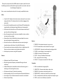
Operation With levels turned down, connect a 6.3mm jack lead from the receiver to the P.A. system or mixer and extend the antenna vertical to the receiver unit. On the handheld transmitter, with the POWER switch off, unscrew the battery cover and connect a good 9V (PP3) battery to the contacts, taking note that the “+” and “-“ connections are correct With the VOLUME control turned fully down (anticlockwise), connect the DC adapter to the receiver unit and then into the mains outlet, making sure that the adapter and lead are in good condition. Switch on the POWER on the handheld transmitter and check that the RF LED is illuminated on the receiver. Switch off the MUTE and speak loudly into the microphone, checking that the AUDIO PEAK LED on the receiver flashes with the loudest sounds Turn up the level on the P.A. system or mixer and then turn up the VOLUME control (clockwise) on the receiver. The microphone should now be heard through the P.A. system or mixer After use, turn down the level on the P.A. system or mixer and then turn down the VOLUME on the receiver, MUTE the transmitter and switch off POWER Disconnect the receiver from the P.A. system and then unplug from the mains If not used for a long period of time, remove the battery from the transmitter VH45B Wireless Microphone System 171.801 Specifications Power supply - Receiver Power supply - Transmitter Carrier frequency Max deviation Dynamic range THD Frequency response Audio output Signal to noise ratio Channel rejection Receiver sensitivity Max continuous battery life Dimensions - Receiver / Transmitter Weight - Receiver / Transmitter 9-15Vdc (adapter supplied) 200mA 9Vdc batter (PP3 type, supplied) 174.5MHz ±25kHz >90dB <0.5% 40Hz-15kHz ±3dB 400mV >90dB >80dB 10dBuV 10 hours 150 x 110 x 35mm / 250 x 50mmØ 190g / 280g 1622 © QTX Sound 2010 USER MANUAL Thank you for your purchase of the VH45B wireless microphone system. Please read the following instructions carefully before using this product to ensure best results and to avoid damage through misuse. Note – no user serviceable parts inside, refer all servicing to a qualified technician. Safety Connect the D.C. adapter to the wireless receiver and ensure the correct mains voltage and that the D.C. adapter and lead is intact before plugging into the mains outlet Ensure that the handheld transmitter has a 9V battery (PP3) installed which is in good condition with adequate charge (alkaline type is recommended) Avoid contact with moisture for any of the system components and keep all parts clear of dust and foreign objects Keep all components away from heat sources (amplifiers, heaters, radiators etc.) and out of direct sunlight Remove battery from the handheld unit and power adapter from receiver when not being used for long periods of time. Position the receiver on a stable surface and take care when placing the transmitter down so that it doesn’t roll and fall off the surface. Clean transmitter and receiver periodically with a dry or slightly damp cloth. Do not use solvents or abrasives on the plastic and metal parts. Avoid impact or pressure on casing of all components Features Stable quartz tuned VHF carrier frequency Multi-level high and mid frequency narrowband filtering to eliminate interference. Individual Mute switch on handheld transmitter to allow muting prior to switching on or off, avoiding clicks and pops LED indicators for Power, RF, Audio Peak, Low battery Audio companding circuitry for accurate dynamics without audible distortion Auto-muting circuitry to eliminate noise when transmitter is not detected Neat and compact design Receiver 1. 2. 3. 4. 5. 6. 7. 8. POWER LED – illuminated when power to receiver is on RF LED – illuminated when receiver detects RF carrier signal AUDIO PEAK LED – illuminates to indicate audio reaching peak level VOLUME – rotate clockwise to increase output level ANTENNA – fold-away VHF telescopic aerial OUTPUT – 6.3mm jack unbalanced audio output CASE – sturdy plastic receiver housing DC INPUT – 2.1mm power connector for 9-15Vdc input Transmitter 1. 2. 3. 4. 5. 6. GRILLE – windshield with integral pop filter LOW BATT LED – illuminates when battery charge is low POWER LED – illuminates to show battery power is on POWER & MUTE – switches to activate battery and mute output GAIN – screw adjustment inside battery compartment to adjust mic gain COVER – screw-on cover for battery compartment