1
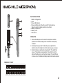
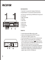
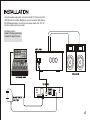
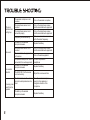
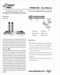
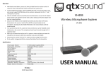
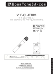
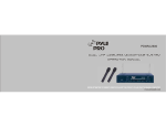
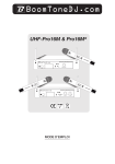
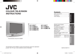
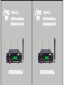
PDWM 5300
PDWM 5300
UHF PLL Diversity Wireless
Microphone System w/ LCD
UHF PLL Diversity Wireless
Microphone System w/ LCD
PDWM5300
OPERATION MANUAL
PDWM5300
OPERATION MANUAL
Thank you for buying the PDWM5300 Wireless System. Please
read through these operation instructions so you will know how
to operate your model properly. After you read it, put it away in a
safe place for future reference.
Avoid exposure of the system to rain or moisture.
No user-serviceable parts inside the system. Refer all servicing to a qualified
technician only.
Handle the wireless system carefully, dropping or other shocks may cause
failure.
Avoid using the system where it may be subjected to heat, such as direct sunlight,
Precautions
Hand-held microphone
Receiver
Installation
Trouble shooting
Specifications
near radiators or other heat sources.
Should any liquid be spilt on the system, stop using it immediately. It may be
possible to dry the system, but you should have it checked by a qualified technician
before using it again.
Take care with the main power adapter and lead. If damaged in any way, do not use
the system and refer to a qualified technician for repair.
Only use the system with the supplied components. Do not attempt to use with any
other main power supply adapter .
If the wireless system is not going to be used for a while, remove the battery to
prevent leakage. In the event of electrolyte leakage inside the battery compartment,
carefully remove the leakage with a damp cloth. Take care not to get battery
electrolyte in contact with your skin, however if it does, wash your hands under a
running tap. If electrolyte comes into contact with your eyes, seek medical advice
immediately.
Only replace the battery with the same or an equivalent type.
Please dispose of old batteries in an environmentally friendly manner in accordance
with the relevant legislation.
Do not use any solvents to clean any part of the wireless system .
1
PARTS DESCRIPTION
1.
2.
3.
4.
Mesh: cartridge inside
Tube
Power LED indicator
Power and Mute switch: Switch on and off the microphone.
Move the switch to middle position to mute the mic.
5. Battery compartment
6. Battery Cover
7. CH selector
6
+
ON
OFF
+
1. Unscrew the battery cover at the end of the microphone. Install the
provided 2 1.5V batteries, taking care to fit it with the correct polarity
connected.
2. According to frequency Chart on the battery cover, adjust the CH
selector to make the microphone to be the same frequency as receiver.
3. Check the battery by switching the microphone ON. The red LED will
come on. This indicates correct operation. If the red LED is dim, this
indicates the battery is low and should be changed. If the red LED does
not come on at all, it indicates the battery is dead and should be replaced.
ON
DIP
1 2 3 4
OPERATION
7
FREQUENCY CHART
CH00 CH01 CH02
795.2MHz 795.8MHz 796.4MHz
CH08
800.0MHz
CH03 CH04
797.0MHz 797.6MHz
CH05 CH06 CH07
798.2MHz 798.8MHz 799.4MHz
CH12
802.4MHz
CH13 CH14 CH15
803.0MHz 803.6MHz 804.2MHz
CH09 CH10 CH11
800.6MHz 801.2MHz 801.8MHz
2
PARTS DESCRIPTION
CH00 795.2MHz
00dB AF
1. Power Switch: Turn on power switch, the display of LCD will illuminate.
2. Power LED indicator: Turn on power switch, this indicator will illuminate.
3. SET: Press once to adjust frequency by UP/DOWN buttons. Press again to exit.
4. UP: Channel UP
5. DOWN: Channel DOWN
6. LCD Display
7. Volume control
8. Antenna A and B
9. Balanced output
10. Unbalanced output
11. 12V DC IN
OPERATION
1. Connect the antennas A and B. Make sure they are vertical.
2. Insert one end of included audio cable into "AF OUT" on rear panel,
and the other end into "LINE IN" of amplifier or mixer.
3. Connect the power adaptor from DC 12V of receiver to a main power socket.
4. Switch on the receiver. The power indicator comes on. LCD display will
displayed on LCD panel.
illuminate. Press SET once, there will be a mark
Now you can adjust frequency by UP/DOWN buttons. Press SET again to exit.
Make sure the microphone and receiver to be of same frequency.
5. Switch on the microphone. A letter "A" or "B" will appear in the top right of the
LCD, indicating the diversity reception. RF strength (in dB) is indicated in the
bottom left corner of the display. When you speak into the microphone, AF
signal will display on the bottom of LCD display panel.
3
Using the supplied audio cable, connect from the AF OUT jack socket to the
LINE IN socket on amplifier. Alternatively, you can connect an XLR cable to
the XLR balanced output. Connect the mains power adaptor from "DC 12V"
jack to a suitable mains power socket.
Installation Location:
At least 3 ft. above ground level
At Least 3 ft. away from wall
MIC LINE
MIC LINE
MIC LINE
MIC LINE
MIC LINE
4
The on air
indicator does
not light up
The wireless microphone is not
turned on.
The microphone receiver is not
turned on.
Turn on the microphone receiver
and the connected audio equipment
The microphone receiver is not
connected properly.
Turn on the microphone receiver
and the connected audio equipment
Frequency not set correctly.
Make sure mic and receiver are
set to the same frequency.
The battery in the wireless
microphone is weak.
No sound
The sound is
distorted
A howling noise
heard from the
speakers.
5
Turn on the wireless microphone
Replace the battery.
The microphone receiver is not
turned on .
The connected audio equipment is
not turned on.
The speakers/headphones. are not
connected to the audio equipment.
The battery in the wireless
microphone is weak.
Turn on the microphone receiver
and the connected audio equipment.
The AUDIO OUT on the receiver
is not set correctly.
Adjust the volume controls.
The distance between the wireless
microphone and speakers are too
close.
Move the wireless microphone
away from the speakers or
change the direction of the
microphone.
The battery in the wireless
microphone is weak
Turn on the audio equipment.
Connect the speakers/
headphones
Replace the battery.
Replace the battery.
A. Overall System
Carrier Frequency:
Frequency Stabilization:
Dynamic Range:
Total Harmonic Distortion:
Frequency Response:
Audio Output Level:
Mix Type:
UHF 795~805MHz
less than 30ppm
more than 90dB
less than 0.5%
40hz~15khz 3dB
separate type:0~ 400mV
0~ 200mV
B. Receiver
Power Supply:
DC 12V
Consume Power:
4W
Signal/Noise Ratio:
more than 90dB
Image & Spurious Rejection:
more than 80dB
Border upon Channel Rejection: more than 80dB
Receiving Sensitivity:
10dBuv(sinad=30dB)
De-emphasis:
50us
C. Transmitter
Transmitting Power:
Modulation Type :
Max Deviation:
Spurious Emission:
Power Supply:
8.5mW
FM,F3F
25KHz
more than 40dB(with carrier)
3V
6