Download BCV-SERIES 100V Indoor Speakers
Transcript
BCV-SERIES
User Manual
100V Indoor Speakers
BC3V
75mm (3”), 60Wmax
BC4V
100mm (4”), 70Wmax
BC5V
130mm (5.25”), 90Wmax
BC6V
165mm (6.5”), 120Wmax
White
Black
White
Black
White
Black
White
Black
952.710
952.711
952.712
952.713
952.714
952.715
952.716
952.717
Introduction
Thank you for choosing the BCV-series indoor speakers. These speakers have been designed to offer high
quality sound for 100V line or low impedance installations. Please read and follow the instructions in this
manual to achieve the best results and avoid damage through misuse.
Installation
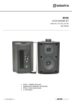
The BCV-series speakers are each supplied with a wall-mounting bracket which
allows 90° lateral adjustment. When fixing to a wall or ceiling, use the bracket to
mark out the fixing points and use appropriate fixings for the substrate that the
speaker will be attached to, ensuring that the fixing is strong enough to bear the
weight load.
Once the bracket is fitted, support the speaker in position and attach top and bottom using the supplied
M6 screw caps and adjust to the required angle. Further M6 mounting points are available at the rear of
the speaker, should it be preferred to use different mounting methods (e.g. 129.130 – 129.124UK)
Connection
BCV-series speakers are connected via 2 spring terminals at the rear of the
enclosure. For 100V operation, use double insulated cable rated to the total
maximum current, calculated as total max tapped power divided by 100V.
With the amplifier switched off, strip the speaker wire ends and connect
100V or “+” wire to the red terminal and connect Common or “-” to the
black terminal. Each model has a 100V transformer built in with various
volume settings or “tappings” available via a rotary switch at the rear
(BC6V example shown).
When used with a 100V line amplifier, select the required maximum
wattage that the speaker should demand from the amplifier. Ensure that
the sum of the wattages of all the speakers attached to the amplifier does
not exceed the recommended output of the amplifier.
When used with a standard (non-100V) amplifier, select the “8Ω” setting and refer to the amplifier
manufacturer’s manual to ensure that total speaker impedance (Ω) is not less than recommended for the
amplifier. It is imperative that the amplifier does not deliver more power than can be handled by the BCV
speaker. Refer to the amplifier manual and specifications below to calculate this. Normally, it is
recommended that the amplifier is capable of the RMS power rating of the speaker but cannot ever
exceed the Max power rating.
Specifications
Model
Woofer
Tweeter
Freq response
Power max : 8Ω
Power rms : 8Ω
Tappings
Dimensions (mm)
Weight
SPL @ 1W/1m
BC3V
75mmØ (3“)
50mmØ (2“)
120Hz - 20kHz
60W
30W
1.5/3/6W, 8Ω
106 x 153 x 106
900g
88dB
BC4V
100mmØ (4”)
25mmØ (1”)
110Hz - 20kHz
70W
35W
2.5/5/10/20W, 8Ω
150 x 195 x 150
1.63kg
88dB
BC5V
130mmØ (5.25”)
25mmØ (1”)
100Hz - 20kHz
90W
45W
5/10/20/30W, 8Ω
180 x 240 x 180
2.38kg
88dB
BC6V
165mmØ (6.5”)
25mmØ (1”)
90Hz - 20kHz
120W
60W
5/10/20/40W, 8Ω
220 x 280 x 220
3.08kg
89dB
Caution
The BCV-series speakers are intended for indoor use. Avoid moist or dusty environments.
Avoid excess heat and exposure to direct sunlight.
Take care not to overload speakers. HF drivers are especially prone to damage through overload.
For 100V installation, take proper care to insulate any contacts within reach of users.
BCV-series User Manual
BCV-series User Manual
Errors and omissions excepted.
Copyright© 2012. AVSL Group Ltd.
BCV-series User Manual


