1
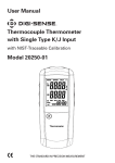
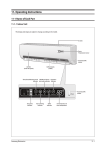
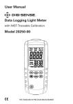
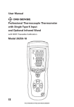
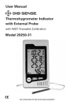
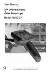
User Manual
Thermohygrometer with Single
Type K Input and Superheat Function
with NIST-Traceable Calibration
Model 20250-12
THE STANDARD IN PRECISION MEASUREMENT
Introduction
The Digi-Sense Thermohygrometer (Model 20250-12)
with Single Type K Input and Superheat Function offers
fast response and high accuracy. This meter is both a digital thermohygrometer and a valuable HVAC diagnostic
tool—it measures humidity, dew point, wet bulb, dry
bulb, temperature, plus target superheat (TSH) and target
evaporator exit temperature (TEET). Meter also features
Min/Max/Hold readings and automatic power-off, and
accepts a wide variety of thermocouple probes. The
instrument is fully tested and calibrated to NIST-traceable
standards. Careful use of this meter will provide years of
reliable service.
Unpacking
Carefully unpack the instrument and accessories from
shipping package. Check individual parts against the list
of items below. If anything is missing or damaged, please
contact Cole-Parmer immediately.
1. Meter
2. One type K flexible probe
3. Carrying pouch
4. Three AAA batteries
5. User manual
6. NIST-traceable calibration report with data
2
Meter Description
1. Thermocouple type K input
2. Thermistor temperature sensor (internal)
3. MODE button
4. ENTER button
5. OUTPUT button
6. °C/°F /
Backlight button
7. SENSOR button
8. MAX/MIN/HOLD button
9. Power On/Off button
10. LCD
11. Humidity sensor (internal)
12. Battery cover
1
2
11
3
6
4
7
5
8
9
10
12
3
Display Functions
1. Low-battery indication
2. Measurement icons (RH, DP, WB, DB)
3. °C/°F icons for upper display
4. Indoor (ID) / Outdoor (OD) icons
5. Upper measurement display of humidity,
dew point, wet bulb, dry bulb, temperature
6. MIN / MAX icons
7. Humidity measurement (%RH) icon
8. HOLD icon
9. T
hermocouple (T/C) and Thermistor (NTC) icons
10. MODE select icons (NORM, TEET, TSH)
11. Auto power-off (APO) indication
12. L
ower measurement display of target superheat
and target evaporator exit temperature
13. °C/°F icons for lower display
2
3
1
5
4
6
7
9
8
11
10
12
4
13
Setup and Operation
Power
Press the Power on/off button to turn unit on.
Taking Measurements
1. Hold the sensor in the area to be tested.
2. Allow adequate time for readings to stabilize.
3. Press the MODE button until the NORM icon is displayed
on the screen.
4. Press the SENSOR button and hold for two seconds to
select the temperature sensor in use: either T/C for
external thermocouple or NTC for internal thermistor.
5. While in the internal sensor (NTC) mode, use the
SENSOR button to toggle between other available measurements: humidity (RH), dew point (DP), wet bulb
(WB), and dry bulb (DB). The icon displayed indicates the
selected measurement.
6. Press the °C/°F / Backlight button to select either °C or °F
temperature units.
Viewing the Min and Max Readings and Hold Function
1. Press MAX/MIN/HOLD button to step through the minimum (MIN), maximum (MAX), and Hold readings.
2. Press MAX/MIN/HOLD button again to exit the
MAX/MIN/HOLD mode.
LCD Backlight
Press and hold the °C/°F / Backlight button for two seconds
to turn backlight on or off.
5
Setup and Operation (continued)
Automatic Power-Off
To conserve battery life, the meter automatically
turns off after 15 minutes. To disable this feature:
1. Turn the meter off.
2. P
ress and hold the MAX/MIN/HOLD button while
powering on.
3. T
he “APO” will no longer been shown on the
display, indicating that the Auto power-off feature
is disabled.
4. N
ote that Auto power-off is re-enabled each time
the meter is turned on.
Using Target Superheat Mode (TSH)
1. P
ress the MODE button until the TSH icon is
displayed on the screen.
a. Blinking numbers indicate that you are in the
unlocked mode and seeing real-time
measurements.
b. S
olid non-blinking numbers indicate that the
reading has been “locked.”
c. P
ress the ENTER button to unlock and take a
new reading, and then press ENTER button
again to relock the measurement.
6
Setup and Operation (continued)
2. While the numbers are blinking (unlocked mode),
press and hold the SENSOR button until the NTC
icon is displayed. Press SENSOR button again to
select either the WB or DB icon.
a. When the WB icon is displayed, place the internal
sensor cap in front of the indoor air return and
press the ENTER button when the reading is
stable.
b. When the DB icon is displayed, place the internal
sensor cap in front of the condenser and press
the ENTER button when the reading is stable.
3. Press the OUTPUT button to display the Target
Superheat temperature in the lower display.
4. Compare the Target Superheat temperature to the
Actual Superheat temperature. Adjust refrigerant
levels accordingly for a fixed restrictor system.
a. If Actual Superheat is higher than Target
Superheat, add refrigerant.
b. If Actual Superheat is lower than Target
Superheat, recover refrigerant.
7
Setup and Operation (continued)
Using Target Evaporator Exit Temperature (TEET)
1. Two thermocouple probes are required for a TEET
measurement.
2. Press the MODE button until the TEET icon is
displayed on the screen.
a. Blinking numbers indicate that you are in the
unlocked mode and seeing real-time
measurements.
b. Solid non-blinking numbers indicate that the
reading has been “locked.”
c. Press the ENTER button to unlock and take a new
reading, and then press ENTER button again to
relock the measurement.
3. Insert thermocouple “A” into a sock and wet the sock.
4. Clip both thermocouples (thermocouple “A” and
thermocouple “B”) in front of the evaporator.
5. Plug thermocouple “A” into the top of the meter.
Note: If “OL” is displayed, then the measurements are
out of range. Retake the temperature measurements
and ensure the temperature inputs are set correctly.
6. Press the SENSOR button until the WB icon is displayed. Press and hold the SENSOR button until the
T/C icon is displayed. When reading is stable, press
the ENTER button to lock the reading.
7. Unplug the thermocouple “A” and plug in the
thermocouple “B“.
8
Setup and Operation (continued)
8. Press the SENSOR button until the DB icon is
displayed. Press and hold the SENSOR button until
the T/C icon is displayed. When reading is stable,
press the ENTER button to lock the reading.
9. Press OUTPUT button and read the Target Evaporator Exit Temperature (TEET) in the lower display.
Note: If “OL” is displayed, then the measurements
are out of range. Retake the temperature measurements and ensure the temperature inputs are set
correctly.
10. C
ompare the Target Evaporator Exit Temperature to
the Actual Evaporator Exit Temperature. The Actual
Evaporator Exit Temperature is the measured
temperature of the air after it has passed through
the evaporator. Adjust airflow accordingly.
a. An Actual Evaporator Exit Temperature below the
Target Evaporator Exit Temperature indicates low
airflow. Increasing airflow can be accomplished
by eliminating restrictions in the duct system,
increasing blower speed, cleaning filters or
opening registers.
b. A
n Actual Evaporator Exit Temperature above the
Evaporator Exit Temperature usually indicates
low capacity. Occasionally airflow is higher than
expected. Look for causes of low capacity such as
refrigerant mischarge or a dirty condenser coil.
If the airflow is high, correct it by lowering the
fan speed.
9
Specifications
Range
Humidity
0 to 100% RH
Temperature, external
type K thermocouple (T/C)
–328 to 2501°F (–200 to 1372°C)
Temperature, internal
thermistor sensor (NTC)
32 to 140°F (0 to 60°C)
Dew point (calculated)
–22 to 212°F (–30 to 100°C)
Wet bulb (calculated)
32 to 176°F (0 to 80°C)
Resolution
Humidity
0.1% RH
Temperature, external
type K thermocouple (T/C)
0.1° (<1000°) or 1° (≥1000°)
Temperature, internal
thermistor sensor (NTC)
0.1°
Accuracy
10
Humidity
±2.5% RH from 10 to 90% RH
±5% RH from 0 to 10% RH and 90 to 100% RH
Temperature, external type
K thermocouple (T/C)
±[0.5% reading + 1.8°F (1°C)]
above –148°F (–100°C)
±[0.5% reading + 3.6°F (2°C)]
below –148°F (–100°C)
Temperature, internal
thermistor sensor (NTC)
±1.8°F (1°C)
Specifications (continued)
Auto power-off
Unit shuts off automatically after
15 minutes to preserve battery life
Operating temperature
32 to 122°F (0 to 50°C)
Storage temperature
14 to 122°F (–10 to 50°C)
Weight
6 oz (173 g)
Dimensions
71⁄4 " x 21⁄2 " x 1" (18.5 x 6.3 x 2.6 cm)
Power
Three AAA 1.5 V batteries
Maintenance
Cleaning and storage
1. The meter should be cleaned with a damp cloth and
mild detergent when necessary. Do not use solvents
or abrasives.
2. Store the meter in an area with moderate temperature
and humidity (refer to the operating and storage range
in the specifications chart earlier in this manual).
Battery Replacement
When the battery power falls low, the low-battery
icon will appear on the screen. Replace the three AAA
batteries by removing the screw holding the rear battery
compartment cover to access the battery compartment.
Ensure that the compartment cover is securely fastened
when finished.
11
Maintenance, Recalibration, and Repair
It is recommended that Digi-Sense products are calibrated
annually to ensure proper function and accurate measurements; however, your quality system or regulatory body
may require more frequent calibrations. To schedule your
recalibration, please contact InnoCal, an ISO 17025 calibration laboratory accredited by A2LA.
Phone: 1-866-INNOCAL (1-866-466-6225)
Fax: 1-847-327-2993
E-mail: [email protected]
Web: InnoCalSolutions.com
For Product and Ordering Information, Contact:
Toll-Free: 1-800-323-4340
Phone: 1-847-549-7600
Fax: 1-847-247-2929
ColeParmer.com/Digi-Sense
1065DGMAN_20250-12 Rev.1
Toll-Free: 1-800-358-5525
Phone: 1-847-327-2000
Fax: 1-847-327-2700
Davis.com/Digi-Sense
Manual Part No. 00100-50