1
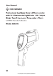
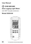
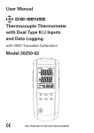
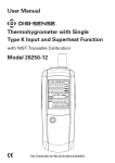
User Manual CFM/CMM Hot-Wire Thermoanemometer with NIST-Traceable Calibration Model 20250-16 Max Min Flow Temp THE STANDARD IN PRECISION MEASUREMENT 2 Introduction The Digi-Sense CFM/CMM Hot-Wire Thermoanemometer (Model 20250-16) provides precision air velocity, airflow, and temperature measurements. The large, easy-to-read backlit LCD includes primary and secondary readings plus numerous status indicators. The instrument is fully tested and calibrated to NIST-traceable standards. Careful use of this meter will provide years of reliable service. Unpacking Check individual parts against the list of items below. If anything is missing or damaged, please contact your instrument supplier immediately. 1. Meter 2. Anemometer telescoping hot-wire probe 3. USB cable 4. Software CD 5. Hard carrying case 6. AC/DC power adapter 7. One 9 V battery 8. User manual 9. NIST-traceable calibration report with data 3 Features • Thermal anemometer is capable of very low air velocity measurements • Slim, telescoping hot-wire probe is ideal for grilles and diffusers • C ombination of hot wire and standard thermistor sensors delivers rapid and precise measurements • Records Max and Min readings with a recall function • M icroprocessor circuit ensures maximum possible accuracy; provides special functions and features • S uper-large LCD with dual function allows air velocity and temperature to be shown at the same time • Data Hold function • A pplications: environmental testing, air conveyors, flow hoods, clean rooms, air velocity, air balancing, fans/motors/blowers, furnace exhaust, paint spray booths 4 Display Elements 1. Low-battery indicator 10. The multiplier of secondary display value 2. Primary Display: air velocity, recording data, or time 11. Flow units 3. Air velocity units 12. Temperature units 4. Secondary display units 13. Flow area units 5. Secondary display data 14. The multiplier of primary display value 6. Record MAX, MIN display 15. Indicates Auto power-off is active 7. Indicates multi-point mean calculation mode 16. Elapsed time 8. Indicates Mean value input mode is active 17. Indicates Data Hold mode is active 9. Indicates Mean value over time mode is active 18 18. Indicates entering or exiting setup mode 16 17 15 1 2 14 3 13 4 12 5 11 10 6 7 8 9 5 Setup Options Use the SETUP button to change area unit, flow area, and sleep mode settings. The meter will store the newer settings in its memory. Note: Setup mode is disabled in MIN, MAX, and Mean modes. Changing a Setup Option 1. Press the SETUP button for 3 seconds to enter or exit Setup mode. When the meter is in Setup mode, the display shows SETUP (refer to Fig. 1). 2. Press UNIT or UNIT button to scroll to the setup option you want to change. AREA 3. Press ENTER button to indicate that you want to change this setting. 4. Press UNIT or UNIT button until the setting you want to use appears on the display. 5. Press ENTER button to store the new setting into memory. Fig. 1 Change the Area Unit of Measure Setting 1. W hile in Setup mode, press UNIT or UNIT button to scroll to the area unit screen (refer to Fig. 2). 2. Press ENTER button. The string “AREA” and area unit of measure will be shown on the screen. AREA 3. Press UNIT or UNIT button to scroll to your desired unit of measure (in2, m2, or ft2). 4. Press ENTER to store the new setting into memory. Change the Flow Area Setting Fig. 2 1. While in Setup mode, press UNIT or UNIT button to scroll to the AREA unit screen (refer to Fig. 2). 2. Press ENTER button to bring up the area value screen (refer to Fig. 3). 3. Press ENTER button again and the area numbers flash. 4. Press UNIT or UNIT button to select the placement of the decimal point. 5. Press ENTER button and the flashing digit will indicate the number ready to be changed. Press UNIT or UNIT button to change the flashing digit from 0 to 9. Fig. 3 6 6. Press the MEAN button to change the station of flashing digit. Press UNIT or UNIT button to change that flashing digit from 0 to 9. 7. Continue until all four numbers have been changed. Then press ENTER button to store the new setting into memory. Auto Power-Off Mode The meter’s default mode is to automatically shut off after 20 minutes of non-use. To disable the auto power-off mode, enter the Setup mode. 1. While in Setup mode, press UNIT or UNIT to scroll to the “SLP ” screen (refer to Fig. 4). Press ENTER to display “On”. 2. Press UNIT or UNIT button until your desired setting appears on the display. Press ENTER to store the new setting into memory. The Auto power-off icon will appear in the upper right-hand corner indicating that the auto power-off mode is activated. Fig. 4 Software Installation • Insert the CD into a PC. • Double click the setup.exe file to launch the software installation program. • Follow the installation wizard to complete the installation. • If the USB driver needs to be updated, please go to the folder /driver on the CD and double click the file CP210xVCPInstaller.exe to update the driver. Setup and Operation Connecting the Vane 1. The vane plug is inserted in the meter’s sensor jack at the top of the meter. The plug and jack are keyed so that the plug can only fit in the jack one way. 2. Turn the plug carefully until it lines up with the jack and then firmly push the plug in place. Do not apply undue force or try to twist the plug side-to-side. 7 Setup and Operation (continued) Taking Single-Point Measurements 1. Press the On/Off button to turn the meter on and allow 5 seconds for the thermal sensor to warm up. 2. Setting the meter to zero: a. O n the probe’s head, slide the sensor cover to the up position to isolate the air velocity sensor from the environment (refer to Fig. 5). Fig. 5 b. Press HOLD/ZERO button until the reading value of air velocity shows zero. 3. Slide the sensor cover to the down position to let the air velocity sensor come in contact with the air (refer to Fig. 6). 4. Extend the telescoping probe to your desired length, up to 41"/104 cm (refer to Fig. 7). 5. Select the desired air velocity units and temperature units. Press the UNIT button to scroll through the air velocity units of measure. Press the UNIT button to select either °C or °F for temperature units. Fig. 6 6. Press the FLOW/TEMP button to bring up the airflow display, then press UNIT button to select either CFM or CMM for airflow units. Fig. 7 7. Place the probe head in the air stream. There are two white arrows on each side of the probe head (refer to Fig. 8). These arrows should point in the same direction as the airflow. Airflow 8. View the readings on the LCD. The upper display shows the Air Velocity reading. The lower display shows the Temperature reading. Press the FLOW/TEMP button to toggle between viewing the Temperature reading and the Airflow reading. 9. Press SETUP button to turn on the backlight; press again to turn off. 8 Probe handle Fig. 8 Taking an Averaged Measurement Over Multiple Points 1. Press MEAN button quickly and the •MEAN icon will appear at the bottom of screen. In this mode, the upper display shows the value of the most recent data point captured and the lower display shows the real-time probe measurement. 2. Press ENTER button to take a data point. The captured data value is shown on the upper display while the lower display continues to show the real-time probe measurement. A data point is captured whenever the ENTER button is pressed. 3. To stop data collection and calculate the mean value, press MEAN button. The •MEAN icon flashes at the bottom of screen and the lower display will indicate the calculated average value of the data taken. 4. To return to measurement mode, press MEAN button. 5. To toggle between the parameters displayed (temperature, flow velocity, and calculated volumetric flow rate), press the FLOW/TEMP button. 6. To change the units of the reading displayed, press UNIT button. Taking an Average Measurement Over Elapsed Time 1. Press MEAN button for 2 seconds. The MEAN icon will appear at the bottom of screen. 2. Press ENTER button to begin timing a measurement. The elapsed time (mm:ss) is shown in the upper display, while the current reading is shown in the lower display. 3. Press ENTER button again to stop the timing cycle. Press ENTER button again to resume the timing cycle. 4. To end the measurement and calculate the average value, press MEAN button. The MEAN icon will flash and the calculated average value is shown in the lower display. 5. To return to the measurement mode, press the MEAN button. 6. To toggle between the parameters displayed (temperature, flow velocity, and calculated volumetric flow rate), press the FLOW/TEMP button. 7. To change the units of the reading displayed, press UNIT button. Holding the Displayed Readings 1. Press HOLD/ZERO button to freeze the readings on the display. The HOLD icon will appear at top of screen, indicating that the meter is in Hold mode and the measurement will remain unchanged. 2. To toggle between the parameters displayed (flow or temperature), press the FLOW/TEMP button. 3. Press HOLD/ZERO button again to turn off the Hold mode. 9 Setup and Operation (continued) Viewing the MAX and MIN Readings 1. Press MAX/MIN button to enter the Max/Min mode. The REC MAX icon will appear at bottom of screen. 2. Press MAX/MIN button again to toggle between the maximum displayed values (REC MAX icon) and the minimum displayed values (REC MIN icon). 3. To toggle between the parameters displayed (flow or temperature), press the FLOW/TEMP button. 4. Press MAX/MIN button and hold for 2 seconds to exit Max/Min mode. 10 Specifications Air velocity Range Resolution Accuracy m/s (meters per sec) 0.1 to 25.0 m/s 0.01 m/s ft/min (feet per min.) 20 to 4925 ft/min 1 ft/min 0.1 km/h km/h (kilometers per hour) 0.3 to 90.0 km/h MPH (miles per hour) 0.2 to 55.8 MPH 0.1 MPH knots (nautical MPH) 0.2 to 48.5 knots 0.1 knots ±(5% + 1 digit) reading or ±(1%+1 digit) full scale, whichever is greater Airflow CFM (cubic feet per min) CMM (cubic meters per min) Air temperature 3 Range Resolution Area 3 0.001 to 100 — 3 0 to 99,999 m /min 0.001 to 100 — Range Resolution Accuracy 0 to 99,999 ft /min 32 to 122ºF (0 to 50ºC) 2 CFM (ft /min) = Air velocity (ft/min) × Area (ft ) 0.1ºF/C 3 ±1.8ºF (1ºC) 2 CMM (m /min) = Air velocity (m/s) × Area (m ) × 60 Display 17⁄8" x 23⁄8" (4.7 × 6 cm) LCD, dual function Memory Max and Min with recall Sampling Approximately every 0.8 second Operating temperature 32 to 122ºF (0 to 50ºC) Operating humidity <80% RH, noncondensing Weight 10 oz (280 g) Dimensions 81⁄4" x 3" x 2" (21 × 7.5 × 5 cm) Power supply 9 V battery or 100 to 240 V, 50/60 Hz Power current Approximately 60 to 90 mA DC 11 Maintenance, Recalibration, and Repair Battery Replacement When low-battery icon appears on LCD, the 9 V battery must be replaced. 1. Disconnect the probe. 2. Remove the meter’s battery cover. 3. Replace the 9 V battery. 4. Close the battery compartment cover. It is recommended that Digi-Sense products are calibrated annually to ensure proper function and accurate measurements; however, your quality system or regulatory body may require more frequent calibrations. To schedule your recalibration, please contact InnoCal, an ISO 17025 calibration laboratory accredited by A2LA. Phone: 1-866-INNOCAL (1-866-466-6225) Fax: 1-847-327-2993 E-mail: [email protected] Web: InnoCalSolutions.com For Product and Ordering Information, Contact: Toll-Free: 1-800-323-4340 Phone: 1-847-549-7600 Fax: 1-847-247-2929 ColeParmer.com/Digi-Sense 1065DGMAN_20250-16 Rev.1 Toll-Free: 1-800-358-5525 Phone: 1-847-327-2000 Fax: 1-847-327-2700 Davis.com/Digi-Sense Manual Part No. 00100-55