1
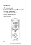
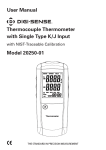
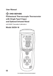
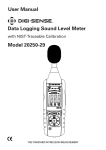
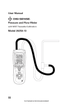
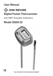
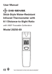
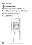
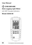
User Manual
CFM/CMM Vane Thermoanemometer
with NIST-Traceable Calibration
Model 20250-14
THE STANDARD IN PRECISION MEASUREMENT
Introduction
The Digi-Sense CFM/CMM Vane Thermoanemometer (Model 20250-14)
measures air velocity, airflow (volume), and temperature. The large, easy-to-read
backlit LCD includes primary and secondary displays plus numerous status
indicators. The meter features 2 memory locations (1 for CFM and 1 for CMM) to
store and recall commonly used area sizes. The instrument is fully tested and
calibrated to NIST-traceable standards. Careful use of this meter will provide
years of reliable service.
Unpacking
Check individual parts against the list of items below. If anything is missing
or damaged, please contact your instrument supplier immediately.
1. Meter
2. Anemometer vane sensor on 3.9 ft (120 cm) cable
3. Three AAA batteries
4. User manual
5. NIST-traceable calibration report with data
Meter Description
1. BACKLIGHT button: Press to turn the
backlight on and off.
2. MAX/MIN button: Use to record and
store the highest, lowest, and average
air velocity or airflow readings.
3. AREA button: Press and hold to
manually enter the area of a duct in
CFM or CMM mode. In AREA mode,
used to select memory locations.
1
2
6
4
8
3
5
4. LCD
5. Power on/off button
6. °C/°F button: Press to unlock the display. Press to switch between °C and °F
units. Meter will beep three times to
indicate change.
7. UNITS button: Press to select the mode of operation. In VEL mode, the meter
displays air speed. In FLOW mode, the meter displays air volume.
8. HOLD button: Press to freeze the displayed velocity and flow reading.
Press again to unlock Hold function.
2
7
Display Layout
•
: Low-battery indicator
• °C / °F: temperature units of measure
Smaller LCD digits at top right of display
for probe temperature
• REC: indicates that min/max function is running (air velocity or airflow measurement)
• MAX: maximum hold for air velocity or
airflow measurement
• MIN: minimum hold for air velocity or
airflow measurement
• AVG: air averaging mode
• HOLD: data hold for air velocity or airflow
measurement
• VEL: indicates that meter is in air velocity
mode
• FLOW: indicates that meter is in airflow
mode
• AREA (m2, ft2): units for area dimensions
• m/s, ft/min, km/h, MPH, knots: air velocity
units of measure
Large LCD digits at bottom of display
for air velocity and airflow
• CFM/CMM: airflow units of measure
• X10, X100: multipliers for air flow readings
Setup and Operation
Connecting the Vane
1. The vane plug is inserted in meter’s sensor jack at the top of meter. The plug
and jack are keyed so that the plug can only fit in the jack one way.
2. Turn the plug carefully until it lines up with the jack and then firmly push the
plug into place. Do not apply undue force or try to twist the plug side-to-side.
3. If the vane is not connected to the meter properly or if the sensor is defective,
the LCD will indicate “OL” in place of a temperature reading.
3
Setup and Operation (continued)
Air Velocity Measurements (Single Point)
1. T
urn on the meter using the On/Off button.
Side view of Vane
Arrow
2. Press UNITS button to select the desired unit of
measure. Note: At power-up the meter will display the last unit of measure previously entered.
Airflow
3. P
lace the sensor in the air stream. Ensure that
the air enters the vane as indicated by the arrow
sticker placed inside the vane.
4. V
iew the readings on the LCD. The large main
bottom display shows the air velocity reading.
The upper right subdisplay shows the temperature reading.
Airflow Measurements (CFM / CMM)
1. T
urn on the meter using the On/Off button.
2. P
ress the UNITS button to select the desired airflow units: CFM (cubic feet
per minute) or CMM (cubic meters per minute). Note: At power-up the
meter will display the last unit of measure previously entered.
3. P
lace the sensor in the air stream. Ensure that
the air enters the vane as indicated by the arrow
sticker placed inside the vane. Refer to the diagram.
The large main LCD display shows the Air Velocity
reading. The upper right LCD subdisplay shows the
temperature reading.
Side view of Vane
Arrow
The meter has 2 memory locations (1 for CFM and
1 for CMM) that can be used to store commonly used
area sizes that you can recall at anytime.
1. P
ress the AREA button until meter beeps twice.
The leftmost digit of the bottom display will begin
to flash.
2. P
ress the MAX/MIN button to move the decimal
point.
3. U
se the UNITS button to change the value of the
first flashing digit (0–9).
4. P
ress the HOLD button to move to the next digit.
5. A
fter all of the digits are entered, press and hold the AREA button
(until it beeps twice) to save the setting into memory and return to
CFM or CMM measuring mode.
4
Airflow
Setup and Operation (continued)
Data Hold (Air Velocity/Airflow)
1. W
hile taking measurements, press the HOLD button to freeze the
air velocity/air flow reading.
2. The HOLD indicator will appear in the middle of the LCD.
3. Press HOLD button again to return to normal operation.
MAX/MIN/AVG Record (Air Velocity/Airflow)
This allows the user to record and view the highest (MAX), lowest (MIN),
and average (AVG) readings.
1. P
ress the MAX/MIN button. The MAX indicator and REC indicator along
with the maximum reading will appear on the LCD and the meter will
begin keeping track of the MAX, MIN, and Average values.
2. P
ress the MAX/MIN button again to view the minimum reading. The MIN
indicator along with the minimum reading will appear on the LCD.
3. P
ress the MAX/MIN button again to view the average reading. The AVG
indicator along with the average reading will appear on the LCD.
Note: Average recording will stop automatically after 2 hours, and the
upper LCD subdisplay will show OFF (only in the average mode).
4. Press the MAX/MIN button again to display current readings. Now only
REC is displayed and the meter will continue recording MAX/MIN/AVG
readings.
5. To clear and stop MAX/MIN/AVG recording and return to normal operation, press and hold the MAX/MIN button until the meter beeps twice.
Automatic Power-Off
To conserve battery life, the meter automatically turns off after 20 minutes.
To disable this feature:
1. Turn the meter off.
2. Press and hold the BACKLIGHT button while turning the meter on.
3. “dis APO” will appear in the display. The Auto power-off feature will now
be disabled.
Note: Auto power-off is re-enabled each time the meter is turned on. Also
note that Auto power-off is disabled in CFM/CMM or Average mode.
5
Specifications
Air velocity
Range
Resolution
Accuracy
m/s (meters per sec)
0.40 to 30.00 m/s
0.01 m/s
±(3% + 0.20 m/s)
ft/min (feet per minute)
80 to 5900 ft/min
1 ft/min
±(3% + 40 ft/m)
km/h (kilometers per hour)
1.4 to 108.0 km/h
0.1 km/h
±(3% + 0.8 km/h)
MPH (miles per hour)
0.9 to 67.0 MPH
0.1 MPH
±(3% + 0.4 MPH)
knots (nautical MPH)
0.8 to 58.0 knots
0.1 knots
±(3% + 0.4 knots)
Range
Resolution
Area
Airflow
CFM (cubic feet per min)
0 to 999,900 ft /min
0.001 to 100
0.000 to 999.9 ft2
CMM (cubic meters per min)
0 to 999,900 m3/min
0.001 to 100
0 .000 to 999.9 m2
Range
Resolution
Accuracy
32 to 122°F (0 to 50°C)
0.1°F/C
4.0°F (2.0°C)
3
Air temperature
6
Circuit
Custom LSI microprocessor circuit
Display
Dual-function 16 mm 4-digit LCD
Sampling rate
Approximately 1 reading per second
Sensors
Air velocity/flow sensor: Conventional angled vane arms with lowfriction ball bearing
Temperature sensor: NTC-type precision thermistor
Automatic power-off
Unit shuts off automatically after 20 minutes to preserve battery life
Operating temperature
32 to 122°F (0 to 50°C)
Operating humidity
<80% RH, noncondensing
Storage temperature
14 to 140°F (–10 to 60°C)
Storage humidity
<80% RH, noncondensing
Weight
7 oz (200 g)
Dimensions
Meter: 63⁄4 " x 21⁄2 " x 1" (16 x 6.2 x 2.1 cm)
Vane sensor head: 23⁄4 " (7 cm) diameter
Cable length: 3.9 ft (1.2 m)
Power
Three AAA batteries
Battery life
Typically 40 hrs. Battery life will be reduced significantly if the
backlight is used continuously.
Battery current
Approximately 8.3 mA DC
Maintenance, Recalibration, and Repair
Battery Replacement
When the low-battery icon appears on the LCD, the three AAA batteries must be
replaced.
1. Disconnect the sensor.
2. The battery compartment is located on the back of the instrument.
The plastic cover must be removed with a screwdriver.
3. Replace the three AAA batteries.
4. Close and rescrew the plastic cover.
It is recommended that Digi-Sense products are calibrated annually to
ensure proper function and accurate measurements; however, your quality
system or regulatory body may require more frequent calibrations. To schedule
your recalibration, please contact InnoCal, an ISO 17025 calibration laboratory
accredited by A2LA.
Phone: 1-866-INNOCAL (1-866-466-6225)
Fax: 1-847-327-2993
E-mail: [email protected]
Web: InnoCalSolutions.com
7
For Product and Ordering Information, Contact:
Toll-Free: 1-800-323-4340
Phone: 1-847-549-7600
Fax: 1-847-247-2929
ColeParmer.com/Digi-Sense
1065DGMAN_20250-14 Rev.1
Toll-Free: 1-800-358-5525
Phone: 1-847-327-2000
Fax: 1-847-327-2700
Davis.com/Digi-Sense
Manual Part No. 00100-53