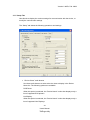
1
User's Manual
TMFLogo Utility
Version 2.60Ea Feb. 2008
Version 2.60Ea Feb. 2008
Notes
(1) Reproduction of any part of this documentation by any means is prohibited.
(2) The contents of this documentation are subject to change without notice.
(3) Comments and notification of any mistakes in this documentation are gratefully
accepted.
(4) This software cannot be used with other equipment that the specified.
(5) EPSON will not be responsible for any consequences resulting from the use of any
information in this documentation.
Trademarks
Microsoft®, Windows®, Windows Vista™, Visual Basic® and Visual C++® are trademarks
or registered trademarks of Microsoft Corporation in the United States and/or other
countries.
EPSON® and ESC/POS® are registered trademarks of SEIKO EPSON CORPORATION.
Other product and company names used herein are for identification purposes only and may
be trademarks or registered trademarks of their respective companies.
Copyright © 2000-2008 SEIKO EPSON CORPORATION
Version 2.60Ea Feb. 2008
Contents
SECTION 1. INTRODUCTION .......................................................................................1
SECTION 2. OUTLINE....................................................................................................2
2.1 TM Flash Logo Utility Introduction ..........................................................................2
2.2 Accessible Devices .......................................................................................................3
2.3 Starting and Closing ...................................................................................................4
2.3.1 Starting the TMFLogo..........................................................................................4
2.3.2 Closing TMFLogo Utility .....................................................................................5
SECTION 3. BASIC OPERATIONS ................................................................................6
3.1 Display Operations......................................................................................................6
3.1.1 Bitmap Selection Tab ...........................................................................................6
3.1.2 Preview Tab ..........................................................................................................9
3.1.3 Logo Upload Tab.................................................................................................13
3.1.4 Logo Printout Tab/ Logo Display Tab ...............................................................17
3.1.5 Setup Tab ............................................................................................................20
3.2 Logo Data Setup and Printing .................................................................................26
SECTION 4. MESSAGES ..............................................................................................30
4.1 Messages ....................................................................................................................30
4.2 Error Messages..........................................................................................................31
SECTION 5. GLOSSARY ...............................................................................................37
SECTION 6. WARNINGS ..............................................................................................38
iii
User's Manual
TMFlogo utility
Version 2.60Ea Feb. 2008
Section 1. Introduction
The TMFLogo Utility is a utility for uploading image data to EPSON devices (TM series
printers or Line Display DM-D500) that have NVRAM bitmap image. You can use this utility
to load external images, register NV bit images, print or display the images, and store the
registered image to files.
This manual explains how to use the TMFLogo Utility.
1
User's Manual
TMFlogo utility
Version 2.60Ea Feb. 2008
Section 2. Outline
This section describes connection configurations and how to make the settings for the
TMFLogo Utility.
2.1 TM Flash Logo Utility Introduction
The TM Flash Logo Setup Utility (hereafter TMFLogo Utility) is a utility for
uploading logo data to the NV bitmap area (flash memory) mounted in the POS
printer/ Line Display and for performing test printing. This can be utilized to reduce
the time required for downloading logo data from the PC to the printer/ Line
Display.
The TMFLogo Utility has the following functions.
1) Starting up as a stand-alone utility (Exe).
2) Checking of the size of the logo data that can be registered at the POS printer
or Line Display.
3) Registering of up to 255 monochrome logo data items, or 9025 color logo data
items.
4) Previewing of bitmap files according to the resolution.
5) Performing different types of color reduction on bitmap.
6) Test printing/displaying of uploaded logo data according to the resolution.
7) Generating data with the attached command for uploading to the devices as
binary files.
Note:
TMFLogo Utility creates a temporary file when displaying the preview image or
registering logo data. When Windows 2000, Windows XP or Windows Vista is
used, installation can be done only by authorized users of the PC installation. The
operation shall be done by the authorized user of the folder in which TMFLogo.exe
is stored.
2
User's Manual
TMFlogo utility
Version 2.60Ea Feb. 2008
2.2 Accessible Devices
TM-H5000II
TM-H5000IIE
TM-H5000IIU
TM-H5000IIP
TM-H5000IIM
TM-H5000IIME
TM-H5000IIMU
TM-H5000IIPM
TM-H5200
TM-H5200E
TM-H5200U
TM-H5200P
TM-H6000II
TM-H6000IIE
TM-H6000IIU
TM-H6000IIP
TM-H6000IIM
TM-H6000IIME
TM-H6000IIMU
TM-H6000IIPM
TM-J2000
TM-J2000E
TM- J2000U
TM- J2000P
TM-J2000M
TM-J2000ME
TM- J2000MU
TM- J2000PM
TM-J2100
TM-J2100E
TM- J2100U
TM- J2100P
TM-J2100M
TM-J2100ME
TM- J2100MU
TM- J2100PM
TM-J7000
TM-J7000E
TM-J7000U
TM-J7000P
TM-J7100
TM-J7100E
TM-J7100U
TM-J7100P
TM-J7500
TM-J7500E
TM-J7500U
TM-J7500P
TM-J7600
TM-J7600E
TM-J7600U
TM-J7600P
TM-L90
TM-L90E
TM-L90U
TM-L90P
TM-L90M
TM-L90ME
TM-L90MU
TM-L90PM
TM-T88III
TM-T88IIIE
TM-T88IIIU
TM-T88IIIP
TM-T88IIIM
TM-T88IIIME
TM-T88IIIMU
TM-T88IIIPM
TM-U220A
TM-U220AE
TM-U220AU
TM-U220AP
TM-U220AM
TM-U220AME
TM-U220AMU
TM-U220APM
TM-U220AM_BM
TM-U220AM_BME
TM-U220AM_BMU
TM-U220APM_BM
TM-U220B
TM-U220BE
TM-U220BU
TM-U220BP
TM-U220BM
TM-U220BME
TM-U220BMU
TM-U220BPM
TM-U220BM_BM
TM-U220BM_BME
TM-U220BM_BMU
TM-U220BPM_BM
TM-U220D
TM-U220DE
TM-U220DU
TM-U220DP
TM-U220DM
TM-U220DME
TM-U220DMU
TM-U220DPM
TM-U220DM_BM
TM-U220DM_BME
TM-U220DM_BMU
TM-U220DPM_BM
TM-U675
TM-U675E
TM-U675U
TM-U675P
TM-U675M
TM-U675ME
TM-U675MU
TM-U675PM
TM-T90
TM-T90E
TM-T90U
TM-T90P
TM-T90M
TM-T90ME
TM-T90MU
TM-T90PM
TM-P60
TM-P60W
(IEEE802.11b)
DM-D500
TM-T88IIIX *1
TM-T88IIIXM *1
3
User's Manual
TMFlogo utility
Version 2.60Ea Feb. 2008
TM-H6000III
TM-H6000IIIE
TM-H6000IIIU
TM-H6000IIIP
TM-H6000IIIM
TM-H6000IIIME
TM-H6000IIIMU
TM-H6000IIIPM
TM-P60PEELER
TM-P60PEELERW
(IEEE802.11b)
TM-T88IV
TM-T88IVE
TM-T88IVU
TM-T88IVP
TM-T88IVM
TM-T88IVME
TM-T88IVMU
TM-T88IVPM
TM-T70
TM-T70E
TM-T70U
TM-T70P
TM-J9000
TM-J9000E
TM-J9000U
TM-J9000P
TM-J9100
TM-J9100E
TM-J9100U
TM-J9100P
BA-T500
BA-T500E
BA-T500U
BA-T500P
EU-T400U
EU-T400P
EU-T400
*1
The operation is not supported in Windows Vista environment.
2.3 Starting and Closing
2.3.1 Starting the TMFLogo
TMFLogo Utility can be started stand-alone.
Executing the TMFLogo.exe starts the utility.
The initial screen is “Setup”. Select the device here.
If the Device Information (INF) file is not located in the same folder as
TMFLogo.exe, the “There is not a Logo registration function” message appears,
and the utility is prevented from starting. Confirm that the Device Information (INF)
file is located in the same folder as TMFLogo.exe.
If the following DLL files are not located in the same folder as TMFLogo.exe, the
“***.DLL not found” message appears, and the TMFLogo Utility is prevented from
starting. Confirm that the following files are located in the folder.
•
SoBase12.dll
•
OReg13.dll
•
PortMg11.dll
•
RcTmLogo.dll
•
EPSLOGO.dll
•
Putil10.dll
•
Various communication DLL files (Port Hcom.dll, Port LPT.dll, Port USB.dll,
Port Net.dll, Port80211.dll)
4
User's Manual
TMFlogo utility
Version 2.60Ea Feb. 2008
2.3.2 Closing TMFLogo Utility
Click the [Close] button in the TMFLogo Utility main dialog box. Alternately, click
the [Close] button in the upper right corner of the window.
5
User's Manual
TMFlogo utility
Version 2.60Ea Feb. 2008
Section 3. Basic Operations
This section describes about the basic operation of the TMFLogo Utility.
3.1 Display Operations
The TMFLogo Utility features the following five tabs: "Bitmap Selection", "Preview",
"Logo Upload", "Logo Printout”/ “Logo Display", and "Setup".
3.1.1 Bitmap Selection Tab
This tab is for selecting a bitmap file from a folder, and adding to a list view as a
logo file.
The “Bitmap Selection” tab allows the following operations and settings.
6
User's Manual
TMFlogo utility
Version 2.60Ea Feb. 2008
• “Selection Logo Files” list view
Displays a list of the selected logo files.
Up to 255 logo files for monochrome or 9025 logo files for color can be
selected.
For TM-J7000, 7100, 7500, 7600, TM-P60 and TM-P60PEELER, you can
select up to 9025 logo files for both monochrome and color.
Choosing any of the items No., Name, or Size in the list view, the contents of
the list view are rearranged according to the following conditions.
· Clicking No. :
In selected order/ Selected order reversed
· Clicking Name : Ascending order/ Descending order
· Clicking Size :
Smaller first/ Larger first
Immediately after TMFLogo Utility is started, the logo file shown here
references the contents of the log file (TMFLogo.ini). Log file stores the
previous setting when the logo file is normally registered at the device or
stored in the file. If the log file is not located in the same folder as the
TMFLogo.exe, nothing is displayed in this list view.
• [Open file] button
Displays the common dialog box for selecting files, and adds the bitmap file
to be registered as logo to the list.
Multiple bitmap files can be selected.
If an error message is shown in the following cases, the logo file cannot be
selected.
· When a logo file that exceeds the size of NV bit image area is selected
· When a logo file that is not a bitmap file is selected
· When a full color (24-bit) BMP file is selected
If the maximum number of logo files that can be registered have already
been selected, the button is disabled, and logo files cannot be added.
• [Remove] button
Removes the logo file(s) selected in the list view from the Selection Logo
Files list view.
Multiple bitmap files can be selected. If the list does not contain at least one
logo file, the button is disabled, and logo files cannot be removed.
7
User's Manual
TMFlogo utility
Version 2.60Ea Feb. 2008
• [Reset] button
Returns the list view selection to the contents of current log file
(TMFLogo.ini).
• “Logo files”
Displays the number of logo files that have been selected, and the number
of files that can be registered.
This is displayed as “Number of selected logo files/ Number of uploadable
files”.
• “Logo size Total”
Displays the total size of the logo files selected in the list view together with
the size of the NV bit image area of the selected device.
This is displayed as "Total size of selected logo files/ Size of device's NV bit
image area". Also, note that, depending on whether it is monochrome or
color, the logo file size may be different.
• [Close] button
Closes the TMFLogo Utility.
• [Help] button
Displays help information that applies to the screen.
8
User's Manual
TMFlogo utility
Version 2.60Ea Feb. 2008
3.1.2 Preview Tab
This tab is for previewing the selected logo file.
The
“Preview” tab allows the following operations and settings.
“Selection Logo Files” list view
Displays a list of the logo files selected by the “Bitmap Selection” tab.
When a logo file item is selected, the bitmap image of the selected logo is displayed
in the “Preview” pane on the right.
The bitmap is displayed in the “Preview” pane in accordance with the selected
Quality option.
The bitmap is displayed in the “Preview” pane, depending on the selected option.
· Clicking No. :
In selected order/ Selected order reversed
· Clicking Name : Ascending order/ Descending order
· Clicking Size :
Smaller first/ Larger first
9
User's Manual
TMFlogo utility
Version 2.60Ea Feb. 2008
• “Logo files”
Displays the number of logo files that have been selected in the list view, and
the number of files that can be registered.
This is displayed as “Number of selected logo files/ Number of uploadable
files”.
• “Logo size Total”
Displays the total size if the logo files selected in the list view together with
the size of the NV bit image area of the selected device.
This is displayed as "Total size of selected logo files/ Size of device's NV bit
image area".
Also, note that, depending on whether it is monochrome or color, the logo file
size may be different.
• “Halftone - method” radio button
Use this button to select a half-tone option. The available half-tone options
are as follows:
· Dither:
This method allows for richer expression of shades of gray at the specified
shades of gray, and therefore is suitable for printing photos, etc. The darker
parts are expressed using the primary ink, and the lighter parts are
expressed using the secondary ink. *1
· Error Diffusion:
This method allows for richer expression of shades of gray at the specified
shades of gray, and therefore is suitable for printing photos, etc. The darker
parts are expressed using the primary ink, and the lighter parts are
expressed using the secondary ink. *1
· None:
This method uses simple color reduction to turn brightness parts of bitmap
files into bi- or tri-values. The darker parts are expressed using the primary
ink, and the lighter parts are expressed using the secondary ink.
· None(Extract):
Use this method when printing bitmap such as logos. The image is
expressed by extracting only color parts that are identical to the primary and
secondary inks.
*1 While dithering uses 1 dot to express 1 pixel, error diffusion uses multiple
10
User's Manual
TMFlogo utility
Version 2.60Ea Feb. 2008
dots for 1 pixel.
• “Halftone - Brightness” slider
This slider adjusts the brightness of the selected bitmap. This slider has five
settings. This option is also disabled when the “None(Extract)” option is
selected (as adjustment is not necessary).
• “Original”/ “After transformation” radio buttons
There are two options used to preview the selected image, as follows:
· Original:
This option displays the selected original bitmap file in the display area.
· After transformation:
This option displays the selected bitmap with the specified settings such as
halftone settings, primary ink and secondary ink.
• “Preview” pane
The image of the logo file selected by “Selection Logo Files” is displayed in
the “Preview” pane according to the selected options.
• “Quality” radio button
For the monochrome option, you can select the display size for previewing.
When the color option is selected, bitmap is displayed in full size in the
preview window. You can select from the following options: Single
Height&Width, Double Width, Double Height, and Double Height&Width.
· Single Height&Width
: Displays in single height and width size
· Double Width
: Displays in double width size
· Double Height
: Displays in double height size
· Double Height&Width : Displays in double height and width size
• “Primary Ink” radio button
Use these radio buttons to select a color for the primary ink. However, when
the monochrome option is selected, this setting is default to only black. The
following options are available when color option is selected:
· Black
: Set the primary ink color of the selected bitmap to be black
· Red
: Set the primary ink color of the selected bitmap to be red
· Green : Set the primary ink color of the selected bitmap to be green
11
User's Manual
TMFlogo utility
Version 2.60Ea Feb. 2008
· Blue
: Set the primary ink color of the selected bitmap to be blue
“Secondary Ink” radio button
Use these radio buttons to select a color for the secondary. It is enabled only
when the color option is selected in the environment settings. The following
options are available when the color option is selected:
· Black
: Set the secondary ink color of the selected bitmap to be black
· Red
: Set the secondary ink color of the selected bitmap to be red
· Green : Set the secondary ink color of the selected bitmap to be green
· Blue
: Set the secondary ink color of the selected bitmap to be blue
· None
: This option does not set any secondary ink color of the selected
bitmap
• [Close] button
Closes the TMFLogo Utility.
• [Help] button
Displays help information that applies to the screen.
12
User's Manual
TMFlogo utility
Version 2.60Ea Feb. 2008
3.1.3 Logo Upload Tab
Use this tab for uploading all logo files selected in the list view to the NV bitmap
image area of the connected device and for uploading the data to the file.
T
he “Logo Upload” tab allows the following operations and settings.
• “Selection Logo Files” list view
Displays a list of the logo files selected on the “Bitmap Selection” tab.
Choosing any of the items No., Name, or Size in the list, the contents of the
list view are rearranged according to the following conditions.
· Clicking No. :
In selected order/ Selected order reversed
· Clicking Name : Ascending order/ Descending order
· Clicking Size : Smaller first/ Larger first
Choosing the [Device] button or the [File] button performs uploading of the
logo files selected here.
13
User's Manual
TMFlogo utility
Version 2.60Ea Feb. 2008
• “Logo Files”
Displays the number of logo files that have been selected in the list view, and
the number of files that can be registered.
This is displayed as “Number of selected logo files/ Number of uploadable
files”.
• “Logo size Total”
Displays the total size of the logo files selected in the list view together with
the size of the NV bit image area of the selected device.
This is displayed as "Total size of selected logo files/ Size of device's NV bit
image area".
Also, note that, depending on whether it is monochrome or color, the logo file
size may be different.
[Device] button
Selecting this button sends the device to the logo file. The message "All Logo
files are written in the NV bit image area of the device. Continue it?" appears
to prompt you for the upload operation. If you select [Yes], a progress screen
appears and all of selected logo files in the list view are written to the NV bit
map image area of the connected Device. The order of the logo files
uploaded follows the order of the logo files displayed in the list view. If the
upload ends with no problem, the "Upload finished, and Writing of bit image
completed. Logo becomes available after the reset of a device." message
appears. When the device is reset, the uploaded logos become enabled and
they can be printed or displayed. Also, when the upload ends with no
problem, the history file (TMFLogo.ini) is updated. If normal communication
with the device cannot be established, an error message appears. In this
case, check that the device is connected, the communication settings are
appropriate, and the cable is connected. For POSPrinter, make sure its
cover is closed. Also, if no logo file is selected, the button becomes disabled.
*Should there be an input/writing error via serial port, check the FIFO setting
for the serial communication. Reduce the value of the setting and then
resend the data. (Recommended value: “1”)
14
User's Manual
TMFlogo utility
Version 2.60Ea Feb. 2008
• [File] button
Use this button to save data for upload to the device as binary files. When
you select this button, the common dialog appears so that you can select a
location to save the file (.tlg).
You can use the COPY command to copy this file to a device, which is same
as selecting the [Device] button to register the logo. If the upload ends with
no problem, the history file (TMFLogo.ini) is updated. If the target drive for
saving the data does not have sufficient space, a message appears and the
data cannot be saved to the location.
Note that if no logo file is selected, then this button cannot be enabled.
• “Set Start Key Code- First Byte”/ “Second Byte” edit box
These edit boxes appear only when the color option is selected, so that you
can specify the start key code. Key codes are similar to file names for naming
bitmap files to register. Each key code consists of two bytes. The code you
can specify is from 32 to 126 (decimal). Note that once a key code is
registered, it cannot be registered again. Also, when multiple logos are
registered, the process always starts from the start key code, and in that
order.
For TM-J7000, 7100, 7500, 7600, TM-P60 and TM-P60PEELER, this edit
box is available in both monochrome and color.
• [Check and delete key code] button
You can use this button to check and delete key codes that have been
registered. When you select this button, the following dialog box appears.
· “Delete NV graphic Image” dialog box
Use this dialog box to check and delete key codes that have been registered.
· [GetKeyCodes] button
Use this button to search key codes that have been registered, and then
display the search result in the key code view window.
· [Delete All] button
This deletes all currently registered key codes in the connected OPOS
Device.
15
User's Manual
TMFlogo utility
Version 2.60Ea Feb. 2008
· [Delete Selection] button
Use this button to delete key codes selected in the key code view window. If
no key code is selected, then this button becomes disabled.
· [OK] button
Use this button to close the dialog box and return to TMFLogo Utility main
window.
• “Device Name” edit box
This edit box displays the name of the currently selected device.
• “Port Name” edit box
This edit box displays the currently selected port name. If a network device is
specified, then its IP address or host name is displayed.
• [Close] button
Closes the TMFLogo Utility.
• [Help] button
Displays help information that applies to the screen.
16
User's Manual
TMFlogo utility
Version 2.60Ea Feb. 2008
3.1.4 Logo Printout Tab/ Logo Display Tab
You can use this tab to test print or display the logo (NV bit image) of the connected
device. If Line Display is selected, then [Print] is changed to [Display].
”Logo Printout”/ “Logo Display” tab provides the following controls:
•
“Printing/ Displaying Range” radio button and edit box
Use them to specify a range for printing or displaying the logos. The following
choices are available for selection.
All: For monochrome devices, use this option to print or display all logo files
(1-255). For color-enabled devices, use this option to print or display all
registered key code data.
Selection: For monochrome devices, use the edit box to specify the range of
logo files for printing or display. In specifying the range, use "," or "-", for
example, "1,5,10", "1-5,8,20-22". For display of only one logo file on Line
Display, the four spin buttons becomes enabled. Use the spin buttons to
specify the position to display the logo file.
17
User's Manual
TMFlogo utility
Version 2.60Ea Feb. 2008
Note that if you enter an incorrect value into the edit box, the "Printing/
Displaying selection is incorrect." message appears and the log cannot be
printed or displayed.
• “Key Code List” list view
This list view is enabled only for color-enabled device. Use it together with
“Selection”. Clicking the [Get Key Code] button gathers the registered key
codes from the target device and displays them in the key code list. You can
then select the [Print]/ [Display] button to print or display the selected key
code data.
For TM-J7000, 7100, 7500, 7600, TM-P60 and TM-P60PEELER, this radio
button is available in both monochrome and color.
• “Quality” radio buttons
Specify a quality for printing or display.
Select between “Single Height&Width”, “Double Height&Width”, “Double
Height” and “Double Width”.
· Single Height&Width : Prints or displays in single height and width size.
· Double Width :
Prints or displays in double width size.
· Double Height :
Prints or displays in double height size.
· Double Height&Width : Prints or displays in double height and width size.
For TM-U675 series printers and TM-U220 series printers, Double Height
and Double Height&Width cannot be selected due to the printer’s
specifications.
• “Header” radio buttons
Used to specify whether the logo number header should be added in front
when each logo is printed.
Use these radio buttons to specify whether to display the logo number on the
image, when Line Display is used for the display.
None Header: Prints or displays without header.
Add Header: Prints or displays with header.
• [Print]/ [Display] button
18
User's Manual
TMFlogo utility
Version 2.60Ea Feb. 2008
Use this button to print or display the logos registered on the target device,
following the selection of “Printing Range”/ “Displaying Range”, “Quality”,
and “Header”.
If normal communication with the device cannot be established, an error
message appears. In this case, check that the device is connected, the
communication settings are appropriate, and the cable is connected. For
POSPrinter, make sure its cover is closed.
• “Device Name” edit box
This edit box displays the name of the currently selected device.
• “Port Name” edit box
Displays the currently selected port’s name.
If an Ethernet device or 802.11b device is selected, the IP address or host
name should be displayed.
• [Close] button
Closes the TMFLogo Utility.
• [Help] button
Displays help information that applies to the screen.
19
User's Manual
TMFlogo utility
Version 2.60Ea Feb. 2008
3.1.5 Setup Tab
Use this tab to display the various settings for communication with the device, or
modify the various basic settings.
The “Setup” tab allows the following operations and settings.
• “Device Class” radio buttons
Use these radio buttons to select a device class to display in the Device
Name list. The following options are available.
POSPrinter:
When this option is selected, the “Device Name” combo box displays only a
list of supported POS printers.
LineDisplay:
When this option is selected, the “Device Name” combo box displays only a
list of supported Line Displays.
20
User's Manual
TMFlogo utility
Version 2.60Ea Feb. 2008
• “Port” radio buttons
Use these radio buttons to select a type of port to display in the Device Name
list. The following options are available.
All:
When this option is selected, the “Device Name” combo box displays devices
connected to all ports.
COM:
When this option is selected, the “Device Name” combo box displays devices
connected to the serial ports only.
LPT:
When this option is selected, the “Device Name” combo box displays devices
connected to the parallel ports only.
USB:
When this option is selected, the “Device Name” combo box displays devices
connected to the USB ports only.
Network:
When this option is selected, the “Device Name” combo box displays devices
connected to the network.
802.11b:
When this option is selected, the “Device Name” combo box displays devices
connected to the IEEE802.11b.
• “Color Setting” radio buttons
Use these radio buttons to select a method to register logos. If the selected
device does not support color, then [Color] cannot be selected. The following
options are available.
Monochrome:
When this option is selected, logos are registered as monochrome.
Color:
When this option is selected, logos are registered as color.
Use key code:
When this option is selected, logos are registered by key code.
When bit images uploaded are printed:
Using the DirectIO method of POSPrinter.
21
User's Manual
TMFlogo utility
Version 2.60Ea Feb. 2008
The DirectIO commands are as follows.
a) When the selected "Monochrome"
"Use key code" is unchecked:
PTR_DI_PRINT_FLASH_BITMAP
"Use key code" is checked:
PTR_DI_PRINT_FLASH_BITMAP2
b) When the selected "Color"
Specify PTR_DI_PRINT_FLASH_BITMAP2 with the DirectIO
method for printing.
• “Memory capacity” combo box
This combo box displays the NV bit image memory capacity. For models that
allow change of memory capacity, these options are available for selection.
To change the memory capacity, press the [SET] button and then make the
change.
Note that when you press the [SET] button, bit images that have been
registered are no longer guaranteed.
• “Free memory” combo box *1
This combo box displays the free NV bit image memory, only when the color
option is selected. The value appears when you press the [Check] button.
• [Check] button *1
For models that allow change in the NV bit image memory capacity, or when
the color option is selected, this button displays the current memory capacity
or the free NV bit image memory.
• [Set] button
Only for models that allow change in the NV bit image memory capacity, you
can set the NV bit image memory capacity as specified in the “Memory
capacity” combo box. Note that once you press the [SET] button, the bit
images that have been registered are no longer guaranteed.
• [Delete KC] button *1
This button is enabled only when the color option is selected and the model
supports color. You can use this button to check or delete key codes that
22
User's Manual
TMFlogo utility
Version 2.60Ea Feb. 2008
have been registered. Selecting this button displays the following dialog box.
· “Delete NV graphic Image” dialog box
Use this dialog box to check or delete key codes that have been registered.
The following functions are available.
· [GetKeyCodes] button
Use this button to find key codes that have been registered, and then display
them in the key code view window.
· [Delete All] button
Use this button to delete all key codes that have been registered.
· [Delete Selection] button
Use this button to delete the key codes selected in the key code view window.
If no key code is selected, then this button becomes disabled.
· [OK] button
Use this button to close the current dialog and return to the main window.
*1 For TM-J7000, 7100, 7500, 7600, TM-P60 and TM-P60PEELER, these
dialog items are available in both monochrome and color.
• “Device Name” combo box
This combo box displays names of the selected device.
If multiple device information (INF) files exist in the same folder where
TMFLogo.exe is stored, then a list of devices appears so that you can select
one from the list.
If the device on the COM port is selected, the following optional settings are
enabled.
If the LPT port, USB port, or an Ethernet device is selected, the following
optional settings are disabled.
• “IP address or Host name” edit box
You can use this edit box only if network device is selected from the “Device
Name” combo box; the edit box displays the IP address or host name.
The IP address or Host name may consist of up to 20 characters.
The IP address should be entered as “***. ***. ***. ***”.
To set or change the IP address or Host name, press the [Update] button
after inputting IP Address or the host name. When a device on the COM, LPT
or USB port is selected, the “IP address or Host name” and [Update] buttons
23
User's Manual
TMFlogo utility
Version 2.60Ea Feb. 2008
become invalid. When an Ethernet device or 802.11b device is selected, the
Port name becomes invalid. The [Update] button is valid only after the
previously set IP address or Host name has been changed.
For the IP address and Host name of the object device, consult with your
network administrator.
For details, refer to the hardware manual.
• [Update] button
Sets the IP address or Host name entered in the “IP address or Host name”
edit box.
This button is valid only when an Ethernet port device or 802.11b port device
is specified and when the specified IP address or Host name has been
changed.
It is invalid when a device on the COM, LPT or USB port is specified.
• “Port Name” combo box
You can use this edit box only if COM, LPT, or USB port device is selected
from the “Device Name” combo box. Specify a port name in the edit box.
The ranges that can be specified are as follows.
· For devices on COM port : COM1 - COM10
· For devices on LPT port :
LPT1 - LPT3
· For devices on USB port :
Set based on the settings of the registry
generated by the TMUSB driver
This button becomes invalid if a device on an Ethernet port or 802.11b port is
specified.
• “Baudrate” combo box
Specifies the baud rate of the COM port.
If BaudrateSel is found in the INF file, the range of this value becomes the
selectable range. If no value exists, any of the rates 2400, 4800, 9600, 19200,
38400, 57600, or 115200 can be selected.
If a Parallel, USB, Ethernet, or 802.11b port device has been specified, the
“Baudrate” is disabled.
For details, refer to the hardware manual.
• “BitLength” combo box
24
User's Manual
TMFlogo utility
Version 2.60Ea Feb. 2008
Specifies the data bit length of the COM port.
The selectable value is “8”.
If a Parallel, USB, Ethernet, or 802.11b port device has been specified by
Printer Name, the “BitLength” is disabled.
For details, refer to the hardware manual.
• “Parity” combo box
Specifies the parity of the COM port.
NONE, EVEN or ODD can be selected.
If a Parallel, USB, Ethernet, or 802.11b port device has been specified, the
“Parity” is disabled.
For details, refer to the hardware manual.
• “StopBit” combo box
Specifies the stop bit of the COM port.
”1” or “2” can be selected.
If a Parallel, USB, Ethernet, or 802.11b port device has been specified, the
“StopBit” is disabled.
For details, refer to the hardware manual.
• “Handshake” combo box
Specifies the handshake setting of the COM port.
DTR or DSR can be selected.
Note that loadable devices for EPSON IR Series, such as printers and
LineDisplay are able to select RTS/CTS.
If a Parallel, USB, Ethernet, or 802.11b port device has been specified, the
“Handshake” is disabled.
For details, refer to the hardware manual.
• [Comm. Test] button
Use this button to run a test on communication with the specified device,
based on the communication conditions. The test checks the device ID of the
connected device and determines whether the logo (NV bit image) can be
uploaded.
When the port setting and device ID are correct, a message appears.
25
User's Manual
TMFlogo utility
Version 2.60Ea Feb. 2008
If the communication settings of the connected device differ from the
specified communication settings, or the device ID of the connected device is
different, an error message appears. In this case, check that the device is
connected, the communication settings are appropriate, and the cable is
connected. For POSPrinter, make sure its cover is closed.
For Line Display, it may not be able to check the device ID, depending on the
DIP Switches or memory Switches. Note that if this is the case, an error
occurs.
For the DM-D500, the following settings allow you to be able to obtain the
device ID.
Main unit
Stand
DIP Switches
2-1 OFF
Memory Switches
5-2 OFF
Jumpers
1=2-3, 2=2-3
• [Close] button
Closes the TMFLogo Utility.
• [Help] button
Displays help information that applies to the screen.
3.2 Logo Data Setup and Printing
This section uses several examples to illustrate how to register logo data and
perform a test print.
1. Starting TMFLogo Utility
The utility can be started stand-alone.
Select and execute TMFLogo.exe in Explorer.
When starting the utility independently, please note that the utility can be started up
only when the necessary files are stored properly in the folder that includes the
TMFLogo.exe file.
2. Executing Communication Test
Before uploading logo data, select the “Setup” tab to confirm that communication
with the object device can be performed normally.
The device to be used and the port settings should be selected and set.
Press the “Comm Test” button to confirm that communication with the object device
26
User's Manual
TMFlogo utility
Version 2.60Ea Feb. 2008
can be performed normally.
If normal communication is not possible, check that the PC and object device are
correctly connected and that the object device is powered on. If normal
communication is still inhibited, check the port and port settings once more.
3. Confirming the NV bit image memory capacity
Before uploading logo data, select the “Setup” tab to confirm the current memory
capacity of the object device.
When the object device is the model that do not allow change in the NV bit image
memory capacity, please proceed to step 4 below.
Press the [Check] button to confirm the current memory capacity of the object
device.
Press the [Set] button to, you can set the NV bit image memory capacity as
specified in the “Memory capacity” combo box.
4. Selecting the Logo Data for Upload
Choose the “Bitmap Selection” tab, and then select the logo data to be uploaded to
the object device.
Press the [Open file…] button and select the logo data (bitmap file “****.bmp”) to be
uploaded.
The selected logo data are displayed in the “Selection Logo Files” list view.
If the “Selection Logo Files” contains logo data not to be uploaded, choose this logo
data and press the [Remove] button to remove the data.
The [Reset] button offers a short-cut way to return upload logo data information to
the logo-uploaded status.
The following example shows how to use the [Reset] button.
Uploading logo data to the device A. (execute 6)
Changing the logo data for updating to the device B. (Change of update contents in
4)
When you want to update the same logo data to both the device B and the device A
=> Press the [Reset] button.
The maximum number of logo files that can be uploaded to the object device is
displayed together with the logo size in the lower left of the screen, and any values
exceeding these should not be selected.
27
User's Manual
TMFlogo utility
Version 2.60Ea Feb. 2008
The number of logo files is indicated in “Logo files” as “Number of currently
selected logo file/ Maximum number of logo file uploadable to object device”.
The total size of logo is indicated in “Logo size total” as “Total size of currently
selected logo data/ Maximum logo data size that can be uploaded to object”.
Please note that the total size of the currently selected logo size is not the total size
of bitmap files but the data size when uploaded to the object device.
5. Confirming the Logo Data Image for Uploading
Choose the “Preview” tab and confirm the image of the logo data to be uploaded to
the object device.
The list of logo data selected in step 4 is displayed in “Selection Logo Files”, and
the logo data can be selected from those in the list. The selected logo data image is
displayed in the pane to the right in accordance with the selected quality settings.
For monochrome, you can select a quality from: "Single Height&Width", "Double
Height&Width", "Double Height" and "Double Width". When confirmation of the
logo data image is not required, proceed to step 6 below.
6. Uploading the Logo Data to the Object Device
Select the “Logo Upload” tab to upload the logo data selected in step 4 to the object
device. The device name and port name registered in the device information are
displayed; be sure to check this again before uploading. If the device to upload is
different, reselect the desired device or port name with the "Setup" tab.
When you press the [Device] button of "Upload", a message to confirm start of
upload appears. Press [Yes] to start uploading logo data to the target device.
7. Confirming printing/display of logo data uploaded to the target device
Select the “Logo Printout”/ “Logo Display” tab to test print/display logo data
uploaded in step 6.
The device name and port name registered in the device information are displayed;
be sure to check this again before uploading. If the device to upload is different,
reselect the desired device or port name with the "Setup" tab.
When you press the [Print]/ [Display] button, the logo data uploaded to the target
device is printed or displayed, according to the settings of "Printing Range”/
“Displaying Range", "Quality" and "Header".
28
User's Manual
TMFlogo utility
Version 2.60Ea Feb. 2008
For monochrome, you can use "Printing”/ “Displaying Range" to specify numbers
for printing or displaying only the specific logo data.
For example;
To print only “1”, enter “1” in the edit box.
To print only “1” and “3”, enter “1,3” in the edit box.
To print from “1” to “3”, enter “1-3” in the edit box.
For color, get the key codes and then select those codes you want to print or
display.
The quality can be selected from the options “Single Height&Width”, “Double
Height&Width”, “Double Height” and “Double Width”. Select in accordance with the
quality to be used for the actually printing.
When "Add Header" is selected for "Header", the registration number of the logo
data and the logo data are printed or displayed together. Select this option in
instances where a large amount has been uploaded, since the registration number
becomes difficult to grasp.
8. Saving Logo Data as a File
Select the “Logo Upload” tab to save the logo data selected in step 4 as a file.
By pressing the [File] button in the “Logo Upload” tab, the logo data to be uploaded
to the object device can be saved as a file. This file is the data that is sent to the
target device when you press the [Device] button. You can also use the COPY
(MS-DOS) command or other communication applications to upload logo data to
the target device. This achieves the same result as using the [Device] button.
29
User's Manual
TMFlogo utility
Version 2.60Ea Feb. 2008
Section 4. Messages
This section describes the messages and the required corresponding remedial actions that
may become necessary in connection with operation of the tabs.
4.1 Messages
Setup
"Communication definition agreed with the device that is connected.”
Communication with the object device could be performed normally during
communication test.
Logo Printout
None
Logo Upload
"All Logo files are written in the NV bit image area of device. Continue it?"
After you press the [Device] button, this message appears to ask you to verify that
you really want to start the upload.
"Upload finished, and Writing of bit image completed. Logo becomes available after
the reset of a device."
This message shows that the upload is finished normally after you pressed the
[Device] button. Check that the device is automatically reset, and then press [OK]
button. (Depending on the device, it may not be reset or it may be difficult to
understand.)
Preview
None
Bitmap Selection
“Do you want to remove all of the selection?”
Confirm whether it really is all right to delete when the [Remove] button is pressed.
30
User's Manual
TMFlogo utility
Version 2.60Ea Feb. 2008
“Sets the list view to the setting of the history file. Continue it?”
Confirm whether it really is all right to change the settings of the “Selection Logo
Files” when the [Reset] button is pressed.
4.2 Error Messages
At startup
“Device Definition (INF) file not found.”
When started up independently, no Device Definition (INF) file is located in the
same folder as TMFLogo.exe. Confirm that a Device Definition (INF) file is located
in the same folder.
“Necessary ***DLL not found”
The DLL file required to start TMFLogo.exe is not found.
Reinstall TMFLogo Utility, etc. and confirm that the appropriate DLL files are
located in the same folder as TMFLogo.exe.
“Size of *** is exceeding the command definition area of ***”
There is a file exceeding the command definition area of the currently selected
device in the logo file that is stored in Log (INI) file. Delete the corresponding file
from the file list, and reregister it after reducing the file size to fit the selected
device.
Setup
“NV bit image area too small. Remove logo files, as it becomes below the size of
NV bit image.”
When started independently and “Bitmap Selection” is selected, the uploaded logo
data size is too large for the new object device after the object device is changed.
Reduce the number of logo data so that it suits the device, or make the logo data
size smaller.
“Communication error. Cannot be received.”
Receive data are not sent from the object device during communication test.
Check whether the object device is correctly connected, and check that the object
device can send and receive the data correctly.
“Communication error. Cannot be transmitted.”
31
User's Manual
TMFlogo utility
Version 2.60Ea Feb. 2008
Data cannot be transmitted to the object device during communication test.
Check whether the object device is correctly connected, and check that the object
device can send and receive the data correctly.
"DeviceID does not agree with the device that is connected."
The object device and the actually used device are not the same during
communication test.
Confirm that the connected device and the selected object device are identical.
“Communication error.”
Communication with the object cannot be performed normally during
communication test.
Confirm the port settings and actual setup environment.
“Device Definition (INF) file not found.”
When independently started and when the device name is specified, the relevant
device’s Device Definition (INF) file is not located in the same folder as
TMFLogo.exe.
After starting up TMFLogo Utility, the relevant device’s Device Definition (INF) file
may have been moved or deleted from the same folder as the one in which the
TMFLogo.exe is located. Return the relevant device’s Device Definition (INF) file to
the same folder as TMFLogo.exe.
“Size of *** is exceeding the command definition area of ***”
There is a file exceeding the command definition area of the currently selected
device in the logo file that is registered in the file list. Delete the corresponding file
from the file list, and reregister it after reducing the file size to fit the selected
device.
32
User's Manual
TMFlogo utility
Version 2.60Ea Feb. 2008
Logo Printout/ Logo Display
“Communication error. Cannot be received.”
Receive data is not transmitted from the object device during printing or displaying.
Check whether the object device is correctly connected, and check that the object
device can send and receive the data correctly.
“Communication error. Cannot be transmitted.”
Data cannot be transmitted to the object device during printing or displaying.
Check whether the object device is correctly connected, and check that the object
device can send and receive the data correctly.
"DeviceID does not agree with the device that is connected."
The object device and the actually used device are not the same during printing or
displaying.
Confirm that the connected device and the selected object device are correct.
“Communication error.”
Communication cannot be established when printing or displaying.
Confirm the port settings and actual setup environment.
“Printing/Displaying selection incorrect“
An error exists in the format when specifying a range for printing or displaying the
logo files. Check the format again.
Logo Upload
“No bitmap file being selected.”
At the time of uploading, the “Selection Logo Files” contains no logo data.
Normally, this does not occur. Select one or more logo data to be uploaded.
“NV bit image area too small. Remove logo files, as it becomes below the size of
NV bit image.”
During uploading, the upload log data size is too large for the device.
Normally, this does not occur. Reduce the number of logo data so that it fits the
device.
33
User's Manual
TMFlogo utility
Version 2.60Ea Feb. 2008
“Communication error. Cannot be received.”
During the upload to the device, data from the target device cannot be received.
Check whether the object device is correctly connected, and check that the object
device can send and receive the data correctly.
“Communication error. Cannot be transmitted.”
During the upload to the device, data cannot be sent to the target device.
Check whether the object device is correctly connected, and check that the object
device can send and receive the data correctly.
"DeviceID does not agree with the device that is connected."
The actual device used is different from the target device, when uploading to the
device.
Confirm that the connected device and the selected object device are correct.
“Communication error.”
Communication with the target device cannot be established, when uploading to
the device.
Confirm the port settings and actual setup environment.
“File could not be created.”
The specified file could not be created at the time of uploading to file.
When specifying “overwrite”, check the attributes of the file. In other cases, there
may be some kind of problem with the disk holding the specified file. Please check
the disk.
“Disk Full.”
When uploading to a file, data could not be uploaded to the specified file because
the disk space is insufficient.
Create empty space on the disk where the specified file is located, or use another
disk with sufficient empty space.
"Could not write on the file."
When uploading data to a file, data could not be uploaded to the specified file.
Something is wrong with the disk holding the specified file. Check the disk.
34
User's Manual
TMFlogo utility
Version 2.60Ea Feb. 2008
"Could not find the file."
When uploading, the logo data to be uploaded is not found in the specified folder.
After the logo data to be uploaded was set, the logo data may have been deleted. If
deleted, copy the logo data to the same folder.
“It is not a bitmap format.”
When uploading, the uploading logo data is not bitmap format.
The logo data to be uploaded is illegal. Use data in correct bitmap format.
“Bitmap file too big.”
When uploading, the logo data size is too big to allow uploading to object device.
Check the size of the logo data to upload, and decrease the size.
Preview
“It is not a bitmap format.”
The upload logo data to be previewed is not bitmap format.
Upload logo data is incorrect. Use data in correct bitmap format.
Bitmap Selection
“Selection of a file is illegal.”
When the [Open file...] button was pressed to select the logo data, an improper file
was selected. Check the folder containing the bitmap file to be selected again.
“255/9025 Logo have already been selected.”
The number of files that can be uploaded to the object device was exceeded when
the [Open file...] button was pressed to select the logo data. Remove unnecessary
logo data, etc. to reduce the number of data to be uploaded to the object device.
“NV bit image area too small. Remove logo files, as it becomes below the size of
NV bit image.”
More logo data than can be uploaded to the object device was selected when the
[Open file...] button was pressed to select the logo data. If this message occurs
when there is no logo data that has been set, the selected logo data is too big for
the object device. Please change the size. If this message occurs when there is
logo data that has been set, remove any data that is not necessary for the selected
logo data.
35
User's Manual
TMFlogo utility
Version 2.60Ea Feb. 2008
“Number of files is too large.”
The number of selected logo data was too large when the [Open file...] button was
pressed to select the logo data. Reduce the number of logo data selected at one
time with the [Open file...] button. The OS restricts the number of files that can be
selected at the same time.
“Bitmap files that were defined with Log file are incorrect.”
When the [Reset] button was pressed, the bitmap file definition written to the Log
file was incorrect. Reset the stored folder and other settings of the bitmap file to the
previous settings that uploaded the logo normally, or upload the bitmap file again.
“File without being found.”
The selected logo data file was not found in the Log file when the [Reset] button
was pressed, or it was not found when the [Open file…] button was pressed.
Check that the file is correctly located in the specified folder.
“It is not a bitmap format.”
The selected logo data file in the Log file was not bitmap format, or the selected
logo data file was not bitmap format when the [Open file…] button was pressed.
Check that the format of the specified file is correct bitmap format file.
“Bitmap file too big.”
The [Reset] button was pressed, the logo data file in the Log file was too big, or the
logo data file was too big when the “Open file…” was pressed. If this message
occurs when there is no logo data that has been set, the selected logo data is too
big for the object device. Please change the size. If this message occurs when logo
data has been set, remove any data that is not necessary for the selected logo
data.
“Size of *** is exceeding the command definition area of ***”
Since the corresponding file is exceeding the command definition area of the
currently selected device, it is unable to register it in the file list. Reregister the file
after adjusting the logo size to fit the selected device.
36
User's Manual
TMFlogo utility
Version 2.60Ea Feb. 2008
Section 5. Glossary
This section describes glossary for the use of the TMFLogo Utility.
Log (INI) file
The Log (INF file) stores information on a logo file that is uploaded correctly to the
object device.
When this log file is started again, or if it is loaded when the [Reset] button on the
“Bitmap Selection” tab is pressed, this information is used as default and displayed
in the “Selection Logo Files” list view of the “Bitmap Selection” tab. At this point, if
no Log file exists, nothing is displayed in the “Selection Logo Files” list view of the
“Bitmap Selection” tab, and the status becomes the one where no log file is
selected.
37
User's Manual
TMFlogo utility
Version 2.60Ea Feb. 2008
Section 6. Warnings
This section describes precautions for the use of the TMFLogo Utility.
The TMFLogo Utility does not aware whether the uploaded logos have been
correctly registered, nor the number of logos actually registered in the device.
Confirm this by performing an actual test print or display.
Basically, registered logos become active once the device is reset.
For monochrome, logos are all uploaded at the same time. Partial upload is not
possible.
For POS printer, uploaded logos can only be printed with a receipt.
For POS printer, if a logo that exceeds the printing area is specified, printing of
the data lying outside the printing area will not take place.
You cannot place "TMFLogo.bmp" in the folder where TMFLogo.exe is located.
This file is used as a temporary file. If it exists, it will be overwritten.
The number of color logos you can register is 9025.
The half tone process applies to all logos for registration. Therefore, if you want
to change the half tone processing method to perform the registration, for color
only, register for each of the settings. For color, as long as the key codes are
not duplicates, it is possible to add registration to logos (NV bit map) that has
already been registered.
Note that if you register color logos where the monochrome logos are already
registered, all registered monochrome logos will be deleted. This is also true
vice versa. Therefore, if you want to mix monochrome logs with color logos, be
sure to apply the monochrome settings to logos you want to turn into
monochrome (by specifying only the black ink), and then register the color
logos.
Communication test and log registration for DM-D500 (Line Display) must use
the stand-alone setting. While it is possible to register logos not using the
stand-alone setting, this is not guaranteed. Also, communication test cannot be
performed outside the stand-alone setting. For more information on the
stand-alone setting, see the explanation of the "Setup" tab.
For Line Display, the multiple test displays always start from the home position,
38
User's Manual
TMFlogo utility
Version 2.60Ea Feb. 2008
and the parts falling outside the physical window cannot be verified. For display
of only one logo file on Line Display (by specifying a number), the four spin
buttons becomes enabled. Use the spin buttons to shift the display start
positions.
When the NV bit image memory capacity is changed, then logos that have
been registered are no longer guaranteed.
39
User's Manual
TMFlogo utility