1
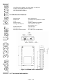
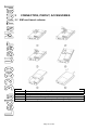
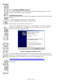
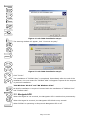
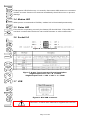
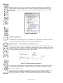
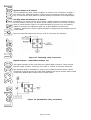
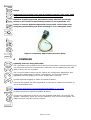
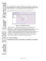
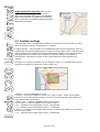
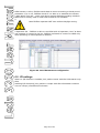
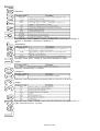
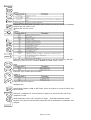
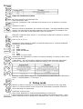
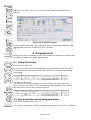
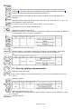
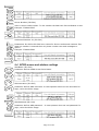
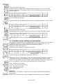
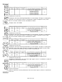
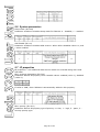
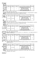
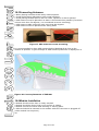
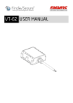
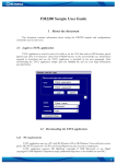
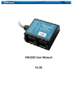
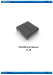
Leda 3200 User Manual
1 INTRODUCTION
1.1 ATTENTION
1.2 INSTRUCTIONS OF SAFETY
1.3 LEGAL NOTICE
1.4 ABOUT DOCUMENT
2 BASIC DESCRIPTION
2.1 PACKAGE CONTENTS
2.2 BASIC CHARACTERISTICS
2.3 MECHANICAL FEATURES
2.4 TECHNICAL INFORMATION
3 CONNECTION, PINOUT, ACCESSORIES
3.1 SIM CARD INSERT SCHEME
3.2 INSTALLING FM3200 DRIVERS
3.3 NAVIGATE LED
3.4 MODEM LED
3.5 STATUS LED
3.6 SOCKET 2×3
3.7 USB
3.8 ACCESSORIES
4 FIRMWARE
5 OPERATIONAL BASICS
5.1 OPERATIONAL PRINCIPALS
5.2 SLEEP MODE
5.3 VIRTUAL ODOMETER
6 CONFIGURATION
6.1 CONFIGURATOR
6.2 SYSTEM SETTINGS
6.3 GPS SETTINGS
6.4 GEOFENCE SETTINGS
6.5 GSM SETTINGS
6.6 GPRS SETTINGS
6.7 SMS SETTINGS
6.8 SEND PARAMETER SETTINGS
6.9 I/O SETTINGS
6.9.1 Monitoring
6.9.2 Event Generating
6.9.3 Hysteresis
7 SMS COMMAND LIST
7.1 SMS SETTINGS FOR FM3200
7.2 SMS COMMAND LIST
getstatus
getweektime
getops
getcfgtime
getgps
Page 2 of 44
getver
getinfo
getio
readio #
setdigout ##
getparam ####
setparam #####
flush #,#,#,#,#,#,#
8 DEBUG MODE
9 PARAMETER LIST
9.1 GLOBAL PARAMETERS
Record search (ID=105)
Link timeout (ID=107)
9.2 DATA ACQUISITION AND SENDING PARAMETERS
Time based acquire interval (ID=11)
Distance based acquire interval (ID=12)
Angle based coordinate acquisition (ID=13)
Data Send interval (ID=270)
Minimum records number in packet (ID=232)
GPRS Enable (ID=240)
GSM Operator list (ID=271)
GPRS Data send week time schedule (ID=272)
SMS Data send week time schedule (ID=273)
SMS Data send allow (ID=250)
24 Records time step (ID=274)
9.3 SECURITY SETTINGS AND PARAMETERS
SMS User login (ID=252)
SMS User password (ID=253)
Server Number (ID=260)
Authorized Number #1 (ID=261)
9.4 GPRS ACCESS AND ADDRESS SETTINGS
APN Name (ID=242)
APN username (ID=243)
APN Password (ID=244)
Data send protocol (ID=231)
Server IP address (ID=245)
Server port number (ID=246)
9.5 GEOFENCE ZONES SETTINGS AND PARAMETERS
GeoFence border width (ID=20)
GeoFence Zone #1 Configuration Parameter (ID=30)
GeoFence x1 (ID=31)
GeoFence y1 (ID=32)
GeoFence x2 (ID=33)
GeoFence y2 (ID=34)
All the rest zones
9.6 SYSTEM PARAMETERS
Sleep mode (ID=000)
GPS Enable (ID=10)
9.7 IO PROPERTIES
Page 3 of 44
IO#1 property parameter (ID=300)
IO#1 priority (ID=301)
IO#1 High level (ID=302)
IO#1 Low level (ID=303)
IO#1 logic operand (ID=304)
IO#1 averaging length (ID=305)
10 MOUNTING RECOMMENDATIONS
10.1 CONNECTING WIRES
10.2 CONNECTING POWER SOURCE
10.3 CONNECTING IGNITION WIRE
10.4 CONNECTING GROUND WIRE
10.5 CONNECTING ANTENNAS
10.6 MODULE INSTALLATION
Page 4 of 44
1
INTRODUCTION
1.1 Attention
Do not disassemble the device. If the device enclosure
becomes damaged in use, isolate the power supply cables
at source before unplugging the power supply connector.
The Leda 3200 is a GSM/GPRS device. All GSM/GPRS
devices produce interference that may affect other nearby
electronic devices.
The device must be connected only by qualified
personnel.
The device must be firmly secured in the desired location
it is installed in.
The programming must be performed using a Class II PC
(with isolated PSU).
Do not expose the device to water and humidity.
Warning! If an incorrect backup battery is used, the device
may explode!
Do not install or handle during a lightning storm.
The Leda 3200 has a USB interface. Only use cables
provided with the device to connect to a PC. Diplomat is
not responsible for any harm caused by using the wrong
cables.
Please note that the internal battery must be plugged in
for the Leda 3200 to operate with the external power
disconnected.
Page 5 of 44
1.2 Safety Instructions
This chapter contains information on how to operate the Leda 3200 safely. By
following these requirements and recommendations, you will avoid dangerous
situations. You must read these instructions carefully and follow them strictly
before operating the device!
The device uses a 10VDC ‐ 30 VDC power supply, consuming no more than 12W. This allows
the unit to be installed in 24VDC commercial vehicles without requiring a voltage reducer.
To avoid mechanical damage, it is advised to transport the FM3200 device in an
impact-proof package. Before usage, the device should be placed so that its LED
indicators are visible, which show the status of operation the device is in.
Before making connections to the vehicle electrics, it is recommended that the battery of
the vehicle is disconnected.
When connecting the connection (1x6) cables to the vehicle, the appropriate
jumpers of the power supply of the vehicle should be disconnected.
Before removing the device from the vehicle, the 6‐way power connector should be
disconnected first.
The device is designed to be mounted in a position which is inaccessible to the operator of
the vehicle. All related devices must meet the requirements of standard EN 60950‐1.
The Leda 3200 is not designed as a navigational device for boats, or in any application where
its failure to operate may lead to a life threatening situation.
1.3 Legal Notice
Copyright © 2011 Diplomat. All rights reserved. Reproduction, transfer,
distribution or storage of part or all of the contents in this document in any form
without the prior written permission of Diplomat is prohibited. Other products
and company names mentioned here may be trademarks or trade names of their
respective owners.
1.4 About This Document
This document contains information about the specifications, applications,
mechanical characteristics, and configuration of the Leda 3200 device.
Acronyms and terms used in document:
• PC – Personal Computer.
• GPRS – General Packet Radio Service.
• GPS – Global Positioning System.
• GSM – Global System for Mobile Communications.
• SMS – Short Message Service.
• AC/DC – Alternating Current/Direct Current.
• Record – A single piece of AVL data stored in FM3200 memory. AVL data
contains GPS and I/O information
• AVL packet - Data packet that is being sent to server during data
transmission. An AVL packet contains from 1 to 30 records.
Page 6 of 44
2
BASIC DESCRIPTION
FM3200 is a terminal with GPS and GSM connectivity, which is able to determine
the object’s coordinates and transfer them via the GSM network. This device is
perfectly suitable for applications which require the accurate location of remote
objects. The Leda 3200 features additional inputs and outputs which let you
control and monitor other devices on remote objects.
The Leda 3200 also has a USB port for NMEA output and configuration.
2.1 Package contents
The Leda 3200 device is supplied to the customer in a cardboard box containing
all the equipment that is necessary for operation. The package contains:
•
•
•
•
The Leda 3200 device.
Input and output power supply cable with a 6-way Tyco connector
GPS antenna
USB cable
2.2 Basic characteristics
GSM / GPRS features:
• Diplomat TM1 dual band module (900/1800 MHz)
• GPRS class 10
• SMS (text, data)
GPS features:
• 50 channel receiver
• NMEA, GGA, GGL, GSA, GSV, RMC, WGS-84 protocol compatible
• -160 dBm sensitivity
Hardware features:
• ARM7 TDMI processor
• 1 MB internal Flash memory
• Built-in movement sensor
• Internal backup battery included
Interface features:
• Power supply: 10VDC to 30VDC @ 12W Max
• USB port
• 2 digital inputs
• 2 open collector outputs
• 3 status LEDs
Special features:
• Multiple event triggers (external sensor, input, speed, temperature, etc.)
• Highly configurable data acquisition and sending
• Multiple Geofence areas
• Sleep mode
• Real-time process monitoring
• Authorised number list for remote access
• Firmware updates via GPRS or USB port
Page 7 of 44
•
•
•
•
Configuration update via GPRS, SMS or USB port
TCP/IP or UDP/IP protocol support
15000 record storing
CE and E-mark certified
2.3 Mechanical features
•
•
•
•
•
GPS Antenna
Power I/O
USB
Power supply
Energy consumption:
• Operation temp.
• Storage temp.
• Storage relative humidity
MCX, Gold Plated
Tyco Multi‐Lock I/O MK‐II C‐175975
Mini USB
10VDC to 30VDC @ 12W Max
GPRS: 200 mA r.m.s Max.
Sleep: 36 mA r.m.s.
‐25°C to +55°C
‐40°C to +70°C
5% to 95 % (non condensation)
7 Figure 2. FM3200 view & dimensions
2.4 Technical information:
Page 8 of 44
Operating time with internal backup battery depends on temperature, amount of data sent,
and battery age (e.g. number of charge/discharge cycles).
For example:
• In sleep mode a new Leda 3200 will give a backup battery operating time of
approximately 3hrs 30mins.
• Operating time for a new Leda 3200 device, working in a typical configuration (records
acquired every 10 sec and sent in packets of 4 records every 60 sec), will be
approximately 2hrs.
Attention! Internal battery must be plugged in, in order for FM3200 to
work from backup battery.
Page 9 of 44
3
CONNECTION, PINOUT, ACCESSORIES
3.1 SIM card insert scheme
1
2
3
4
5
6
Open the SIM holder by sliding the cover as shown
Slot the SIM card into the cover as shown
Close the SIM holder and slide the cover to lock it in place
Plug in the backup battery
Slide the enclosure together ensuring the lugs engage the slots
Insert and tighten the screws (do not overtighten!)
Page 10 of 44
3.2 Installing FM3200 drivers
In order to configure the Leda 3200, “MS Windows XP Service Pack 2” or later
version of MS Windows must be installed.
“MS Windows XP SP2”
Before connecting the Leda 3200 to the computer, the special Hot Fixes must be
installed:
1) Hotfix KB918365 (usbser.sys 5.1.2600.2930);
2) Hotfix KB935892 (usbccgp.sys 5.1.2600.3116).
After installing the HotFixes, reboot your PC.
Power up the Leda 3200 and connect it to the computer. “Found New Hardware
Wizard” for “FM32XX Port” will appear. Choose “Install from a list or specific
location” (Figure 3) and press “Next”.
Figure 3. FM3200 installation step 1
In the new window, choose “Search for the best driver in these locations” and
check the “Include this location in the search” box. Then click browse and specify
the location of the “FM22XX.inf” file, it can be downloaded from
http://www.diplomat.co.uk/downloads/FM32/FM32XX/FM22XX.inf
Click “Next”.
Page 11 of 44
Figure 4. Leda 3200 installation step 2
The warning window will appear, click “Continue Anyway”.
Figure 5. Leda 3200 installation step 3
Click “Finish”.
The installation of “FM32XX Port” is completed. Immediately after the end of the
installation, the new wizard for “FM32XX GPS” will appear. Repeat all the steps as
in previous installation.
“MS Windows XP SP3” and “MS Windows Vista”
No HotFix installation is required. Proceed with the installation of “FM32XX Port”
and “FM32XX GPS”.
3.3 Navigate LED
When GPS signal is not received, the Navigation LED is switched on permanently.
When GPS signal is received, the Navigation LED blinks every second:
When FM32XX is operating in Sleep mode Navigation LED is off.
Page 12 of 44
If Navigation LED blinks every 11 seconds, that means GPS antenna or connector
is short circuited. Remove the antenna immediately should this occur to prevent
damage.
3.4 Modem LED
When power is connected to FM3200, modem led is illuminated permanently.
3.5 Status LED
If the device is operating correctly the Status LED should blink. If this LED does
not blink it means that the device has invalid firmware or other malfunction.
3.6 Socket 2×3
Figure 6. 2×3 socket pinout
Figure 7. 6-way Tyco Connector Pinout Description.
*Digital input Level <2V = 0 = FALSE
*Digital Input Level > 2.5V < 30 V = 1 = TRUE
3.7 USB
Figure 8. Mini USB connector
The Leda 3200 has an industry standard Mini USB interface
connector. A USB to Mini USB lead is supplied with the unit.
Page 13 of 44
When plugged into a PC, the Leda 3200 creates two COM-Ports: “FM32XX Port”,
which can be used as system port (to flash firmware and configure the device)
and “FM32XX GPS” as a GPS serial output of standard NMEA 0183 data at 9600
baud rate.
Figure 9. COM-Ports
3.8 Accessories
Diplomat has a range of approved accessories for Leda Vehicle Trackers including
Panic Footswitches, Pushbuttons and Vehicle Immobiliser Kits.
Digital Inputs – Panic Buttons, Door Sensors, etc.
The Digital Inputs are either “TRUE” or “FALSE”. The inputs of the Leda 3200 are
“Active High” as they require a voltage to be applied to them in order for the Leda
3200 to consider an input to be “TRUE”. With nothing connected to a Digital Input
the Leda 3200 will consider that input to be “FALSE”
Figure 10. Panic button connection
To connect a Panic button to the Leda 3200 it is necessary to connect one wire of
the button to a permanently available voltage source and the other wire of the
button to a Digital Input.
In this way when the button is pressed (i.e. the contact is closed) a voltage gets
applied to the input and the Leda 3200 considers the input as being “TRUE”.
When the button is released, the Leda 3200 considers that input to be “FALSE”.
Page 14 of 44
Ignition Sense In A Vehicle
This is perhaps the most simple condition to sense as the “Accessory” supply in
the vehicle (the cable designed to supply vehicle accessories when the ignition
key is turned to the ACC position) can be directly connected to the Digital Input.
Sensing Other Conditions In A Vehicle
Sometimes you might need to sense when a switch contact is closed to ground.
In these cases, there may not be an actual voltage that can be sensed. In cases
when a vehicle sensor output is a signal that goes to ground (e.g. the battery
negative terminal) an additional relay has to be installed to convert this
“negative” signal into a positive signal suitable for applying to the Digital Input of
a Leda 3200.
Here is a typical arrangement using a relay to overcome the problem:
Figure 11. Inverting relay connection
Digital Outputs – Immobiliser Relays, etc.
The Digital Outputs of the Leda 3200 are called “Open Collector” which means
that an output is either “Floating” when OFF or “Pulled-To-Ground” when ON.
One method used to immobilise a vehicle is to inhibit the starter motor. When
connected as shown below the Leda 3200 disables the engine starter when output
is ON. More details about relays can be found below.
Figure 12. Immobiliser relay connection
Page 15 of 44
Relays
Important! It has been found that the Digital Outputs of the Leda 3200
may not be able to fully energise some automotive relays!
Diplomat supplies approved Immobiliser Relay Kits that specifically
include a pre-wired current limiting resistor in series with the coil.
Failure to use the Diplomat approved relay kit will result in the relay
energizing momentarily and then resetting to a non energized state.
Figure 13. Diplomat Approved Automotive Relay
4
FIRMWARE
Updating firmware using USB cable
The Leda 3200 is an intelligent device and its functionality is always improving. As
new firmware versions are released the Leda 3200 can be updated via the USB
cable or Over-The-Air via GPRS.
The current firmware version can be read by the configurator application. See
configuration description for details. Alternatively, the firmware updater
application will also display the current version that is running.
Contact Diplomat Support to obtain the latest firmware.
A special FM Updater PC utility application is required to update the firmware. It
can be downloaded from:
http://www.diplomat.co.uk/downloads/FM32/Updater_1.1.0.1.zip
Firmware must to be copied to Updater directory.
Connect the Leda 3200 to the PC with the supplied USB cable. Launch the “FM
Updater” application, select the correct COM port, click connect and update. The
update process may take several minutes.
Page 16 of 44
Figure 14. FM updater screen
Updating firmware via GPRS
Firmware can also be updated via GPRS by commanding the Leda 3200 to
connect to a firmware update server.
A special SMS command is sent to the Leda 3200 which includes the IP address
and Port number for the Leda 3200 to connect to.
The server details are as follows:
Server IP: 109.200.19.99
Server port: 7037
The firmware update command is described later in this document
5
OPERATIONAL BASICS
5.1 Operational principals
The Leda 3200 tracking device is designed to acquire records and send them to a
server. Records contain GPS and I/O information. The Leda 3200 uses its internal
GPS receiver to acquire GPS data based on three data acquire methods: timebased, distance-based and angle-based methods.
The way in which each method works is described in the GPS section of this
manual. All data is stored in real-time in flash memory and sent in ‘bundles’ via
GPRS or SMS channels to conserve airtime usage. GPRS mode is the most
preferred data sending mode. SMS mode is mostly used in areas without GPRS
coverage or when GPRS usage is too expensive.
GPRS and SMS settings are described in the GPRS section. The Leda 3200
communicates with a server using a custom data protocol. The Diplomat Data
protocol is described in a seperate “protocols” document.
The Leda 3200 can be managed by SMS commands. The SMS Command list is
described in SMS COMMAND LIST section. The whole of the Leda 3200’s
configuration can be performed either via GPRS or via SMS.
Page 17 of 44
5.2 Sleep mode
The Leda 3200 can enter sleep mode (standby mode) under two conditions:
• FM3200 does not detect movement.
• FM3200 does not send or receive any data for 5 minutes. This means that if
coordinate recording interval is less than 5 minutes, FM3200 will never enter
sleep mode.
The Leda 3200 exits sleep mode when it detects movement again.
While in sleep mode, the Leda 3200 instructs its internal GPS receiver to enter a
low-power sleep mode which means it will not generate any location data. The
corresponding decrease in power usage reduces drain on the vehicle battery.
5.3 Virtual odometer
The Leda 3200 uses a “Virtual Odometer” to calculate travelled distance as a
separate I/O element.
When the Leda 3200 detects movement, it starts counting distance using the GPS
signal: every second it checks current location and calculates distance between
the current and the previous point. It keeps adding these intervals until it is time
to make a record, then the Leda 3200 generates a record containing its current
location and the current odometer value, which is equal to the sum of all the
distances it has measured.
When the record is made, the Virtual Odometer resets to zero and the distance
calculation starts all over again.
Note that the Virtual Odometer works independently of any other records being
generated using elapsed time, distance and angle change intervals. Instead, it
uses a separate set of virtual points which are established independently every
second, and accumulates the distance between them.
6
CONFIGURATION
6.1 Configurator
A brand new Leda 3200 device has default factory settings. Settings should be
changed according to your application and your GSM operator information.
The Leda 3200 configuration is most easily performed via the “FM3200
Configurator” PC application. The latest FM3200 Configurator version can be
downloaded from:
http://www.diplomat.co.uk/downloads/FM32/FM3200_Configurator.zip
The FM3200 Configurator application operates on Microsoft Windows OS and uses
MS .Net Framework 2.0 or higher. Please ensure that MS .Net Framework 2.0 or
later is installed on your PC before starting configurator. Latest MS .Net
Framework version can be downloaded from official Microsoft web page.
Device configuration is performed via the supplied USB cable. Configuration
process starts from loading FM3200 Configurator program and selecting COM
port.
Page 18 of 44
The Leda 3200 has one user editable profile stored in Flash no. 1 memory and
one extra profile stored in Flash no. 0, which cannot be edited by the user. The
profile from Flash no. 0 is used by system and cannot be selected as active, while
profile from Flash no. 1 is fully editable and can be selected as active.
Changes of profile parameters must be saved to Leda 3200 Flash no. 1.
Figure 15. Configurator window
•
•
•
•
•
‘Read from Flash’ – reads configuration parameters from Flash memory.
‘Save to Flash’ – saves configuration parameters to Flash memory.
‘Load from file’ – allows user to load configuration saved in .XML extension file.
‘Save to file’ – allows user to save currently entered settings to a file.
‘Load default profile’ – loads default FM3200 settings that later can be
modified. This procedure must be performed before entering new parameters.
• ‘Get IMEI’ – reads FM3200 IMEI number. This number is unique for every
FM3200 and usually servers recognize different devices by this number.
• ‘Reset device’ – reboots FM3200 and displays processor firmware version.
• ‘Load CPU FW via PORT ½’ – updates the firmware version.
6.2 System settings
System settings menu has only one parameter – Sleep mode. It can be enabled
or disabled by turning it on or off. See sleep mode description for more details.
Page 19 of 44
6.3 GPS settings
GPS settings define GPS data acquiring methods and frequencies.
Figure 16. GPS configuration
Device is checking if the time between last saved record and current time is equal
or higher than Time based acquire interval. If so, FM saves record to memory. If
not, FM checks if the distance from last record to current record is equal or higher
than Distance based acquire interval. If so, saves the record to memory. If not
and speed is higher than 10km/h, then FM is checking if angle difference between
last record and current record is equal or higher than Angle based acquire value.
If so, saves
the record to memory. This check is being performed every second.
FM3200 is able to collect records using three methods at the same time: time,
distance and angle based data acquisition:
Time based data acquiring (Min. period)
Records are being acquired every time when
defined interval of time passes. Entering zero
means that data will be recorded as fast as
possible (every second). Entering zero disables
data acquisition
depending on time.
Distance based data acquiring (Min. distance)
Records are being acquired when the distance
between previous coordinate and current position
is greater than defined parameter value. Entering
zero means that data will be recorded every 0
meters (as fast as possible – every second).
Entering zero disables data acquisition depending
on distance.
Page 20 of 44
Angle based data acquiring (Min. angle)
Records are being acquired when angle
difference between last recorded coordinate
and current position is greater than defined
value. Entering zero disables data acquisition
depending on angle.
6.4 Geofence settings
The Leda 3200 has 5 configurable Geofence zones and it can generate an event
when a defined Geofence zone border is crossed.
• Frame border – frame border is an additional border around Geofence zone. It
is additional area around defined zone used to prevent false event recording when
object stops on the border of the area and because of GPS errors some records
are made inside area and some outside. This border defines a ‘hysteresis’
characteristic such that an event is only generated when both borders are
crossed.
See Figure 17 below for details: As an example, Track 1 is considered as having
entered the Geofence area while Track 2 does not.
Figure 17. Geofence border
• Shape – can be rectangular or circle
• Priority – priority of Geofence event: low, high or panic. These levels define
priority of event information sending to server. See I/O element description for
more details about priorities.
• Enter event – enable or disable zone entering event
• Exit event – enable or disable zone leaving event
• X1 – geofence zone left bottom corner X coordinate
• Y1 – geofence zone left bottom corner Y coordinate
• X2 or R – geofence zone upper right corner X coordinate (radius of circle when
Circular zone used)
• Y2 – geofence zone upper right corner Y coordinate
Page 21 of 44
Figure 18. Geofence configuration
6.5 GSM settings
‘GSM Settings’ allows you to set the exact protocol used for data transfers – TCP
or UDP. ‘Min Saved Records’ defines the minimum number of records (i.e. records
of coordinates and I/O data) that should be transferred as a bundle in one single
data connection to server. If the Leda 3200 does not have enough coordinates to
send to server, it will check the number of accumulated records again after the
time interval defined in the ‘Send Period’ parameter (see section 6.8 below).
Figure 19. GSM configuration
6.6 GPRS settings
‘GPRS Settings’ define important parameters for connecting to a server via GPRS:
GSM provider’s APN name, APN username and APN password (username and
password may be optional according to your provider), the destination server IP
address and the port it is listening on.
Some operators use specific authentication for a GPRS session – CHAP or PAP. If
one of these is used then the APN name should be entered followed by a colon
and the letter ‘c’ or ‘p’. So, for example, if the APN name is ‘internet’ with CHAP
authentication, then enter the APN name as ‘internet:c’
Information about APN, username and password credentials should be provided
by your GSM operator.
Figure 20. GPRS configuration
Page 22 of 44
6.7 SMS settings
• SMS data send – enable or disable periodic data and event SMS use. Note, that
this does not affect replies to messages – they are always sent to sender’s
number.
• SMS send timeout – SMS send timeout (recommended 60 sec.)
• SMS Login – module login for SMS
• SMS Password – module password for SMS
• Server phone number – authorized server phone number for SMS requests,
configuration, 24-coordinates and event binary SMS
• Authorised phone numbers – other authorised numbers that are allowed to
control the Leda 3200 remotely.
Module login and password, server and authorised number list is
used to protect the Leda 3200 device from unauthorised access.
Device only accepts messages from a list of authorised numbers
and with proper device login and password. Numbers must be
without “+” or “00” prefix. If no authorised numbers are
entered, Device accepts messages from all numbers. Server
phone number automatically counts as an authorised number.
Figure 21. SMS configuration
6.8 Send Parameter settings
Send parameters window allows to set GPRS and SMS data send periods, sending
schedules, set allowed operator list.
• Send period – GPRS data sending to server period. Module makes attempts to
send collected data to server every defined period. If it does not have enough
records (depends on parameter Min. Saved Records described above), it tries
again after defined time interval
• Time step – FM3200 is improved with 24-coordinates-in-one-SMS sending
mechanism. 24- coordinates-in-one-SMS mechanism is used in areas where no
GPRS coverage is available.
Module collects data and sends to server binary SMS containing information about
last 24 collected points with interval between them defined in time step field. SMS
sending schedule is set in SMS Week Time tab. 24-Coordinates SMS decoding is
described in Protocols” document.
• GPRS Context Week Time tab – most GSM billing systems charge number of
bytes (kilobytes) transmitted per session. During the session, FM3200 makes
connection and transmits data to a server. FM3200 tries to handle session as
much as possible. Session can last hours, days, weeks or session can be closed
after every connection in certain GSM networks – this depends on GSM network
provider. GPRS Context Week Time defines session re-establish schedule if
session was closed by network. New GPRS context is opened if time is 10 minutes
till time checked in table. Therefore if all boxes are checked, FM3200 is able to
open new connection
anytime. At scheduled time match FM3200 checks for GPRS session activity. If
Page 23 of 44
GPRS session is alive, FM3200 sends data to server according to Send period
parameter. If it is not, FM3200 checks if it is able to re-establish the session.
• SMS Week Time tab – week time allows setting SMS data sending schedule.
SMS mode is mostly used in areas where GPRS is not available.
2
Note FM3200 operates GMT time without daylight saving.
4
• Operators list – FM3200 is able to use GPRS with all operators, but if at least
one operator is entered in the list, FM3200 is allowed to connect to GPRS only
while operating in listed operator’s network.
Figure 22. Send Parameters configuration
6.9 I/O settings
When no I/O element is enabled, AVL packet comes with GPS information only.
After
enabling I/O element(s) AVL packet in couple with GPS information contains
current value(s) ofenabled I/O element.
Page 24 of 44
25
There are two types of operations with I/O elements: simple
monitoring and event generating. Monitoring method is used
when current I/O information needed with regular GPS
coordinates. Event generating method is used when additional
AVL packet is needed when current value of I/O exceeds
predefined High and Low levels. I/O settings allow defining I/O
event criteria.
Figure 23. I/O settings
• Enabled or disabled field – allows enabling I/O element so it is added to the
data packet and is sent to the server. By default all I/O element are disabled and
FM3200 records only GPS coordinates.
• Priority – AVL packet priority – low, high or panic. Regular packets are sent as
Low priority records. When low priority event is triggered, FM3200 makes
additional record with indication that the reason for that was IO element change.
When High priority is selected, module makes additional record with high priority
flag and sends event packet immediately to the server by GPRS. Panic priority
triggers same actions as high priority, but if GPRS fails, it sends AVL packet using
SMS mode if SMS is enabled in SMS settings.
• High and Low levels – define I/O value range. If I/O value enters or exits this
range, FM3200 generates event. “Generate event” parameter defines when to
generate event – when value enters defined range, exits it or both.
• Averaging constant – it is an I/O event delay parameter. In some applications
there is no need to generate events on every I/O range enter/exit immediately.
Sometimes it is necessary to wait some time interval before event generating.
Averaging constant allows to set I/O event delay (averaging). If I/O value is
entering or leaving predefined range, it must have same value for Averaging
constant time. 1 Averaging constant value equals 20 milliseconds.
Page 25 of 44
6.9.1 Monitoring
I/O monitoring starts after enabling I/O element and setting up I/O parameters
as it is shown below:
Page 26 of 44
6.9.2 Event Generating
Events happen when the value of enabled I/O intersects thresholds (enter, exit or
on both)predefined by High and Low level thresholds. Table below defines all
available values of I/O settings.
6.9.3 Hysteresis
I/O elements can generate events according to hysteresis algorithm. If I/O event
operand “Hysteresis” is selected, events will be generated as it is shown in the
illustration below:
Figure 24. Event generation according hysteresis algorithm
27
Page 27 of 44
7 SMS COMMAND LIST
Note: The SMS command list is under constant revision. Please do not assume that this
manual is complete or accurate. Commands may change between different software
versions.
Please always use the latest Manuals published by Diplomat.
7.1 SMS settings for FM3200
Figure 25. SMS login, password, server phone number
and authorized phone number configuration
Essential fields in ‘SMS Settings’ are ‘Login’ and ‘Password’. This login and
password should be used with every SMS sent to FM3200 as identifiers and
means of protection from SMS from unauthorised numbers.
Command structure:
<login><space><password><space><command>
Example:
asd 123 getgps
Page 28 of 44
7.2 SMS command list
Page 29 of 44
Getstatus
Example: Data Link: 0 GPRS: 1 Phone: 0 SIM: 0 OP: 24602 Bat: 4 Signal: 5
Service: 1 NewSMS: 0 Roaming:0 SMSFull: 0
29
getweektime
Example: Clock Sync: 1 DOW: 4 Time 12:58 Weektime: 6538
getops
Example: GSM OP LIST: 0. 24602
getcfgtime
Example: Last Configuration was performed on: 2010.4.15 5:45:19
getgps
Example: GPS:1 Sat:7 Lat:54.71473 Long:25.30304 Alt:147 Speed:0 Dir:77
Date: 2007/8/24 Time: 13:4:36
Page 30 of 44
getver
Example: Code Ver:0.48.17 Device IMEI:353976010139156 Device ID:000001
Modem APP Ver:2007.11.07
Modem REV Ver:04.13.00
30
getinfo
Example: INI:2007/8/24 10:15 RTC:2007/8/24 12:43 RST:2 ERR:11 SR:182
BR:0 CF:0 FG:0 FL:0 UT:0 SMS:2 NOGPS:0:0 GPS:3 SAT:7 RS:7
getio
Example: DI1:0 DI2:0 DO1:0 DO2:0
readio #
Example: IO ID:3 Value:0
setdigout ##
Sets digital outputs to ON or OFF state. Value is written as a row for OUT1 and
OUT2 values.
Example: ‘setdigout 01’ will set OUT2 to high level, while OUT1to low level.
getparam ####
Read parameter value. ID consists of 4 digits – first digit identifies profile,
second, third and fourth identifies parameter ID as described in Parameter List
chapter.
Page 31 of 44
Response details Description
ID Profile number and parameter ID
Value Parameter value
Example: ‘getparam 1245’ command will request server IP address in profile1.
31
setparam #### #
Sets new value for parameter. ID consists of 4 digits – first digit identifies profile,
second, third and fourth identifies parameter ID as described in Parameter List
chapter. In value field a new parameter value is entered.
Example: ‘setparam 1245 127.0.0.1’ will change configured IP address in profile1
with new value
flush #,#,#,#,#,#,#
Initiates all data sending by GPRS to specified target server. Comma separated
parameters go as numbered:
1.# - IMEI
2.# - APN
3.# - GPRS LOGIN
4.# - GPRS PASSWORD
5.# - IP
6.# - PORT
7.# - MODE (0-TCP/1-UDP)
Parameters are separated by comma (no spaces needed). In case you don’t need
to enter parameter
(Login/Pass) – do not put space, simply put comma and write next parameter.
Example: opa opa flush 353976012555151,banga,,,212.47.99.62,12050,0
Example: FLUSH SMS Accepted. 11 records found on FLASH. Minimum Records to
Send: 1. GPRS Enabled: 1. Time Sync: 1.
32
8 Debug mode
FM3200 is able to transmit its current state when connected to PC using USB
cable. It is used to detect errors and provide information to possible solutions
when operating as unexpected.
Download Terminal from:
http://www.Diplomat.co.uk/Downloads/Software/Terminal.rar.
After launching terminal choose baud rate 115200 and hardware control – none.
Select COM port which is assigned to “FM22XX Port”. Click on ‘Start Log’ button
Page 32 of 44
and save a new file. Then click ‘Connect’ to start receiving messages from
FM3200.
Figure 26. Terminal window
To debug NMEA GPS data, select COM port which is assigned to “FM32XX GPS”,
change baud rate value to 9600 and click “Connect”.
33
9 Parameter List
FM3200 uses only one profile, therefore all changes to parameters must be done
in profile1 (profile0 is for global parameters).
9.1 Global Parameters
Record search (ID=105)
Record search parameter is responsible for record searching order. Value of 0
arranging data starting from newest, while value of 1 arranging data starting
from oldest.
Link timeout (ID=107)
Link timeout in seconds, indicates link timeout after last record sending.
Disconnection from server is not immediate after data packet is sent. Module
disconnect from server after indicated timeout.
9.2 Data acquisition and sending parameters
Time based acquire interval (ID=11)
Time interval in seconds, indicating condition to acquire new record. 0 – disabled.
Page 33 of 44
Distance based acquire interval (ID=12)
Distance in meters, indicating condition to acquire new record. Record is stored
when the distance between previous record is greater than parameter’s value. 0 –
disabled
Angle based coordinate acquisition (ID=13)
Angle in degrees, indicating condition to acquire new record. If angle difference
between last recorded coordinate and current position is greater than defined
value, new record is stored. This parameter is operational, when speed is higher
then 10km/h. 0 – disabled
34
Data Send interval (ID=270)
Time interval in seconds, indicating frequency of sending data to server. 0 –
disabled.
Minimum records number in packet (ID=232)
Minimum number of records in one data packet that can be sent to server. This
parameter has
higher priority than Data Send interval (ID=270).
GPRS Enable (ID=240)
Parameter allows or does not allow using GPRS. If GPRS is not allowed value is 0,
if GPRS is
allowed – 1.
Page 34 of 44
GSM Operator list (ID=271)
Parameter defines operator list. According to this list module allows GPRS
connection only while operating under listed operators. GSM operator codes are
comma separated. Example: 24601, 24602, 24705…24503
35
GPRS Data send week time schedule (ID=272)
This parameter manages when it is allowed to open GPRS context. When module
starts it is prohibited to open the context. When modem’s GPRS context is being
closed (for example changing network) it is allowed to open it only at defined
time. It is possible to allow connections every 10 minutes up to once per day.
Example value: 7FFFFFFFFFFFFFFFFFFFFFFFFFFFFFFFFFFFFF
Format is described in the next chapter.
SMS Data send week time schedule (ID=273)
Parameter defines SMS data sending according to week time schedule. This
parameter is used to set data sending on selected week days and hours. Minimum
time step is 10 minutes.
Example value: 7FFFFFFFFFFFFFFFFFFFFFFFFFFFFFFFFFFFFF
Schedule parameter format
Time is defined as 20 byte array. First byte of array defines week days, the
following 18 bytes define timestamps with 10 minute interval and the last byte is
unused. In first byte, first bit (LSB) defines if module should connect to GPRS
(send SMS) on Monday, second bit – on Tuesday and so on up to seventh bit –
which means Sunday. Eighth bit (MSB) is not used. If bits value is 0 then device
is not allowed to open GPRS context, but if it is already open – does not close it.
If value is 1 it will
work as day minutes are defined in rest of the bytes.
Day’s minutes are defined by 18 bytes (144 bits). Every n’th bit (beginning from
the first bit (LSB) and ending 18 bytes 8’th bit (MSB)) indicates every 10’th
minute of the day (day has 1440 minutes).
Example:
GPRS will be allowed on Monday to Friday at 8:00 and 16:00 GMT the following
value should be configured:
Page 35 of 44
00011111 00000000 00000000 00000000 000000000 00000000 00000000
000000011 00000000 00000000 00000000 00000000 00000000 0000000011
00000000 00000000 00000000 00000000 00000000
Red bits indicate that GPRS will be allowed everyday except Saturdays and
Sundays.
Blue bits indicate 480 and 720 minutes (480 min = 8 h and 720 min = 16 h). So
the parameter value should be:
1F 00 00 00 00 00 00 01 00 00 00 00 00 01 00 00 00 00 00
It should be sent as UTF8 encoded string.
SMS Data send allow (ID=250)
Parameter allows or does not allow using binary SMS to send Avl data. If SMS use
is not allowed value is 0, and 1 if allowed.
24 Records time step (ID=274)
Module is able to send binary SMS which contains 24 coordinates. Parameter
ID=274 defines time step (in milliseconds) between each coordinate.
36
9.3 Security settings and parameters
SMS User login (ID=252)
User login is used to ensure module security. Used in every SMS that is sent to
device.
Example: ba321
SMS User password (ID=253)
User password is used to ensure module security. Used in every SMS that is sent
to device.
Example: ab123
Page 36 of 44
Server Number (ID=260)
Value is server GSM number. To this number the SMS with 24 coordinates is sent.
Example: 37060012345
Authorized Number #1 (ID=261)
Parameters ID=262 to ID=269 have values for 8 more authorized numbers If at
least one number is entered then only those number can send messages to
device.
Example: 37060012346
37
9.4 GPRS access and address settings
APN Name (ID=242)
Parameter defines GPRS Access Point Name.
APN username (ID=243)
Parameter defines APN username. In case operator does not use username for
login, value should be empty.
APN Password (ID=244)
Parameter defines APN password. . In case operator does not use password for
login, value should be empty.
Page 37 of 44
Data send protocol (ID=231)
Parameter defines GPRS data transport protocol. Module can use TCP or UDP
transport protocol to send data to server. For TCP protocol value is 0, for UDP
protocol value is 1.
Server IP address (ID=245)
Parameter defines Avl data destination server IP address. Example: 212.47.99.62
Server port number (ID=246)
Parameter defines Avl data destination server port number. Example: 12050
38
9.5 Geofence zones settings and parameters
This chapter explains how to get all parameters for the first GeoFence zone (all ID
numbers are for the 1st zone). And at the end of the chapter (part 1.6.7) is
presented a table with the IDs of all the rest GeoFence zones.
GeoFence border width (ID=20)
GeoFence border thickness, measured in meters.
GeoFence Zone #1 Configuration Parameter (ID=30)
GeoFence Zone #1 Configuration is 1st zone basic settings parameter: GeoFence
zone shape, priority, zone entering event, zone-leaving event. There are two
GeoFence zone shapes: circle, rectangle. GeoFence Zone priority has eight levels
(0 to 7). Parameter value is four bytes that have bit encoded values.
0 bit – GeoFence zone shape
1-3 bits – GeoFence event priority
4 bit – Zone entering event
5 bit – Zone leaving event
6-31 bits reserved
Example:
Value to set: 51 (integer) is [M]00110011[L], where GeoFence Zone shape is
Rectangular,
priority of 1, Zone entering event is enabled, Zone leaving event is enabled.
Page 38 of 44
GeoFence x1 (ID=31)
Parameter has two meanings dependent on zone shape. If shape is rectangular,
then ID=31 is left down corner X coordinate in WGS. If shape is circle, then
ID=31 is center of that circle X coordinate in WGS.
Sample value: 25.30528
GeoFence y1 (ID=32)
Parameter has two meanings dependent on zone shape. If shape is rectangular,
then ID=32 is left down corner Y coordinate in WGS. If shape is circle, then
ID=32 is center of that circle Y coordinate in WGS.
39
GeoFence x2 (ID=33)
Parameter has two meanings dependent on zone shape. If shape is rectangular,
then ID=33 is right upper corner X coordinate in WGS. If shape is circle, then
ID=33 is radius of circle with center of ID=31 and ID=32.
GeoFence y2 (ID=34)
If shape is rectangular, then ID=34 is right upper corner Y coordinate in WGS. If
shape circle, ID=34 is not used.
All the rest zones
Other 5 GeoFence zones parameters have the same logic as shown in GeoFence
Zone #1.
Page 39 of 44
9.6 System parameters
Sleep mode (ID=000)
Parameter enables or disables sleep mode for FM4100: 0 – disabled, 1 – enabled.
GPS Enable (ID=10)
Parameter enables or disables GPS receiver. When GPS is disabled value is 0, and
1 when enabled.
40
9.7 IO properties
IO properties – are additional data sources which are recorded along with usual
GPS data.
IO#1 property parameter (ID=300)
Parameter defines IO property value. Possible values: enabled (value 1), disabled
(value 0).
If value is ‘CAN’, then CAN data is automatically added to this property.
IO#1 priority (ID=301)
Parameter defines IO property type of priority: 0 is low, 1 – high, 2 – panic, 3 –
security priority type.
Page 40 of 44
IO#1 High level (ID=302)
Parameter defines high value of triggered IO property. This parameter is used to
set thresholds for IO properties to generate events.
IO#1 Low level (ID=303)
Parameter defines low value of triggered IO property. This parameter is used to
set thresholds for IO properties to generate events.
41
IO#1 logic operand (ID=304)
Parameter defines when event is sent: 0: on range exit, 1: on range entrance, 2:
both, 3: monitoring.
IO#1 averaging length (ID=305)
Parameter defines IO property sample length to average. If no averaging needed
default value is 1.
Other IO property elements are configuring in same logic. All IO elements
parameter list is below.
Page 41 of 44
42
10 MOUNTING RECOMMENDATIONS
10.1 Connecting Wires
• Wires should be connected while module is not plugged in.
• Wires should be fastened to the other wires or non-moving parts. Try to avoid
heat emitting and moving objects near the wires.
• The connections should not be seen very clearly. If factory isolation was
removed while connecting wires, it should be applied again.
• If the wires are placed in the exterior or in places where they can be damaged
or exposed to heat, humidity, dirt, etc., additional isolation should be applied.
• Wires cannot be connected to the board computers or control units.
10.2 Connecting Power Source
• Be sure that after the car computer falls asleep, power is still available on
chosen wire. Depending on a car, this may happen in 5 to 30 minutes period.
• When module is connected, be sure to measure voltage again if it did not
decrease.
• It is recommended to connect to the main power cable in the fuse box.
10.3 Connecting Ignition Wire
• Be sure to check if it is a real ignition wire – power does not disappear while
starting the engine.
• Check if this is not an ACC wire (when key is in the first position, most
electronics of the vehicle are available).
• Check if power is still available when you turn off any of vehicles devices.
• Ignition is connected to the ignition relay output. As alternative, any other
relay, which has power output, when ignition is on, may be chosen.
10.4 Connecting Ground Wire
• Ground wire is connected to the vehicle frame or metal parts that are fixed to
the frame.
• If the wire is fixed with the bolt, the loop must be connected to the end of the
wire.
• For better contact scrub paint from the place where loop is connected.
Page 42 of 44
10.5 Connecting Antennas
• When placing antennas avoid easily reached places.
• Avoid GPS antenna placement under metal surfaces.
• Avoid placing FM3200 device near car radio, speakers or alarm systems.
• GPS antenna must be placed so its state is as horizontal as possible (if antenna
is leant more than 30 degrees, it is considered incorrect mounting).
• GPS antenna cable cannot be bent more than 80 degrees.
• GPS antenna must be placed sticker facing down
Figure 27 GPS antenna correct mounting.
It is recommended to place GPS antenna behind dashboard as close to the
window as possible. A good example of GPS antenna placement is displayed in a
picture below (area colored green).
Figure 28. Correct placement of FM3200
10.6 Module Installation
• Module should not be seen or easily reached.
• Module should be firmly fixed to the surface or cables.
• Module cannot be fixed to heat emitting or moving parts.
• SIM card should be inserted in the module while the connector is plugged off
(while module has no power).
44
Page 43 of 44
11 CHANGE LOG
Page 44 of 44