1
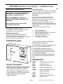
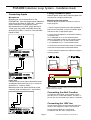
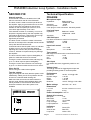
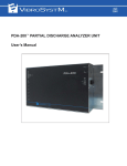
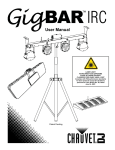
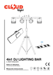
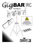
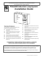
This document should be incorporated in the maintenance manual. Do not leave with the system operator. PDA PDA200E Induction Loop System Range Installation Guide Technical Features The PDA200E is a current mode induction loop amplifier with the following features: Up to 120m2 coverage - ideal for most applications Straightforward internal screw connections Ideal for electrical contractors - no audio connectors Wall mounted for permanent installation Internal controls avoid user tampering Mid-range tone control to improve intelligibility Alert input & tone generator for door bells, fire alarms etc. Fully automatic compressor-limiter controls output level Balanced microphone and line level controls Phantom power on microphone input for electret microphones 100V line input from PA system Larger coverage from smaller cable due to 2Ω loop drive Complete with full instructions and ‘loop fitted’ sticker Contractor kits available for retail, offices, places of worship etc. Additional line and microphone inputs using Outreach plates PLEASE READ THESE INSTRUCTIONS CAREFULLY BEFORE INSTALLING AND/OR MAINTAINING THIS EQUIPMENT These instructions are general and cannot be considered to cover every aspect of loop amplifier installation. No responsibility can be accepted by the manufacturers or distributors of this loop amplifier for any misinterpretation of an instruction or guidance note or for the compliance of the system as a whole. The manufacturers policy is one of continuous improvement and we reserve the right to make changes to product specifications at our discretion and without prior notice. E&OE Document No DCP0002129 JC 28/04/04 Rev 6 Page 2 AU- GND AU- AU+ PDA200E Induction Loop— Example Installation AU+ V+ GND AU Bus in+ AU Bus inV+ AU Bus in+ AU Bus in- This schematic shows an example system which utilises a desk mounted microphone (AMT) wired direct into the PDA200E , two wall mounted mics (APM) and a 100V line feed from a public address system. The alert trigger has been wired to a doorbell which, when activated, plays a 2kHz tone through the loop. PDA200E Induction Loop System - Installation Guide Document No DCP0002129 JC 28/04/04 Rev 6 PDA200E Induction Loop System - Installation Guide General precautions Important Information Do not test wiring with an insulation tester (Megger) with any equipment connected as the 500 Volt test voltage will destroy these devices totally. This system must only be installed and maintained by a suitably skilled and technically competent person. Unpacking Upon receipt of the amplifier shipment, please inspect for any damage incurred in transit. If damage is found, please notify your supplier and the transport company immediately. THIS EQUIPMENT IS A PIECE OF CLASS 1 EQUIPMENT AND MUST BE EARTHED State date, nature of damage and whether any damage was noticed on the shipping container prior to unpacking. Please give the waybill number of the shipping order. The installation guide must not be accessible to the user. The unit should not be placed in areas; No responsibility can be accepted by the manufacturers or distributors for any misinterpretation of these instructions or for the compliance of the system as a whole. 1. 2. 3. Equipment guarantee This equipment is not guaranteed unless the system is installed and commissioned in accordance with national standards by an approved and competent person or organisation. PDA200E Amplifier 4. 5. 6. with poor ventilation exposed to direct sunlight with high ambient temperature or adjacent to heat generating equipment with high humidity or dust levels susceptible to vibration on the exterior of a building A basic system comprises a PDA200E amplifier and sound source. The PDA200E is supplied separately or as part of a kit with Outreach plates. The PDA200E has direct inputs for microphones and other sound sources. These inputs can be expanded by fitting several Outreach plates. All kits include a PDA200E amplifier and 6m of Belden 8723 cable per Outreach plate. PDA200E Kits System Information AKM1 Meeting/seminar room kit AKL1 Lecture room kit Audio Frequency Induction Loop Systems (AFILS) offer clear sound to people who wear hearing aids fitted with a telecoil. AKT1 TV/Music Lounge kit AKW1 Place of Worship 1 kit AKW2 AFILS transmit the amplified sound; e.g. music, speech etc to the hearing aid and minimise distracting and annoying background noise. Place of Worship 2 kit with radio microphone AKR1 Waiting room kit AKH1 Health & Fitness Club kit AKU1 Retail unit kit Page 3 Document No DCP0002129 JC 28/04/04 Rev 6 PDA200E Induction Loop System - Installation Guide FIRST FIX Before any of the following is carried out ensure that the mains power supply is isolated. Equipment Location All equipment must be sited indoors and MUST NOT be subjected to conditions likely to affect its performance, such as damp, salt air, water, extreme temperatures, physical abuse, etc. Wall mounted equipment should be sited at an easily accessible height. Remove knockouts Decide how the wiring will be brought into the panel and remove the required knockouts for cable entry (a basic system would require three for mains, microphone or outreach plates and loop cable). If a knockout is removed fill the hole with a good quality cable gland. Unused knock-outs must be securely blanked off. Observe proper segregation of wiring. Mains, loop and low power wiring must not come into contact eg feeding through the same gland or allowing wires of one type of connection to cross those of another. If the 100V input is used these wires must also be segregated from the other inputs The PDA200E can be surface mounted using the three mounting holes in the unit base. The mounting holes are designed for No. 8 roundhead or countersunk wood screws. Any dust or swarf must be kept out of the enclosure and great care must be taken not to damage the wiring or components. Mains Wiring Connect mains to the PDA200E The 230V a.c. cable MUST enter the enclosure via one of the knock-outs at the top right hand corner of the enclosure. This equipment requires fixed wiring, using three core cable (no less than 0.75 mm2 and no more than 2.5 mm2) fed from a 3 Amp fuse spur fitted with an all pole isolating switch with at least a 3mm gap on each contact, located no more than 3 metres from the amplifier. Wire as in the diagram. If removing lid remove the four wiring loom connecting blocks Correctly terminate the mains input lead using the fixed mains connector on the base of the unit . The metal lid may be removed for ease of mounting, undo the screws at the top of the front panel using the 3 mm Allen key supplied. Page 4 This equipment is designed for permanent mains connection and must not be connected using a plug and socket. Document No DCP0002129 JC 28/04/04 Rev 6 PDA200E Induction Loop System - Installation Guide Fitting Outreach Plates Connecting Inputs Microphones Microphones can be wired direct to the PDA200E Mic input as shown below. Balanced mics should be wired as GND, MIC - and Mic + (which carries the 12V phantom power) Non balanced mics ie AMT (after removal of 3.5mm jack plug), AML and AMD should be wired as live to Mic+, screen to Gnd and MIC– linked to GND. Outreach plates can be daisy-chained together and connected as a single line level input. Mounting Outreach plates Outreach plates should be mounted on a 25 mm single gang box. 1. Run the 2-pair screened audio cable (supplied in kits) from the PDA200E to the first Outreach plate and secure with an appropriate gland. 2. Connect the PDA200E to the Outreach Plates in accordance with: V+ on PDA200E to V+ on the Outreach Plate GND on PDA200E to GND on the Outreach Plate L+ on PDA200E to AU+ on the Outreach Plate L- on PDA200E to AU- on the Outreach Plate 3. Connect the second Outreach Plate (if required) to the first Outreach Plate as described above. 4. Fit the Outreach plate to the outlet box using the screws provided. AU_BUS_IN+ AU_BUS_IN+ AU_BUS_IN- AU_BUS_IN- V+ GND AU+ AU- V+ GND AU+ AU- PDA200E Line Level Unbalanced line level inputs should be wired as diagram below with live to Lin+, screen to Gnd and Lin - linked to GND. Balanced Line level should be wired as the outreach plate (omitting the V+ connection) NB, For installation of Outreach plates purchased before Jan 2003 please contact your supplier. Connecting the Alert Function To trigger the alert signal, close a switch across pins ALT and V+ on the alert header. The alert input can also be connected to fire alarms / doorbells Connecting the 100V line This should be wired into the termination block as shown in the diagram on Page 2 of the manual. Ensure that the cables are connected in accordance with the colour coding shown. Page 5 Document No DCP0002129 JC 28/04/04 Rev 6 PDA200E Induction Loop System - Installation Guide Installing the Loop Cable The loop cable should be laid in a single turn and wired into the Termination block as shown in the diagram on page 2 of the manual. In the vast majority of cases loop cables are normally mounted horizontally around the perimeter of the room to be covered, either at ceiling or floor height. They may also be installed under carpet by using flat loop cable. Do not install the loop cable closer than 1.2M to a hearing aid position Overspill and more complex installations Overall length The magnetic field is not confined to the area within the loop and the signal may be heard in adjacent areas such as a corridors and up to three times the width of the loop away. 2m 2m If this is a problem there are special designs of loop that can reduce the overspill field. The AFILS British Standard (BS 7594) suggests several technically complex solutions that are reasonably effective but are rarely employed due to high cost. A low-cost but effective method to reduce overspill is to make a smaller loop, typically in the centre of a room. The smallest practicable loop for floor or ceiling mounting (up to 3 metres high) is 2 metres square. This will provide a reasonable field at head height above the loop and up to four metres away in all directions. This loop may be installed above a suspended ceiling or in plastic conduit in the floor. Flat cable may be used under carpet. In larger installations overspill can be reduced by laying the loop in an ‘electric grill’ pattern. Each pattern can be considered as a many pronged fork. Overall width 0.75 m The amplifier may be connected to any point on the loop Loop Amplifier The pattern should be spaced approx. 2m from the nearest wall / next pattern, prongs of the fork should be spaced approx. 2m apart and should be approx. 2m wide, prongs should extend approx. 0.75m off the base of the fork. If the loop user is confined to a bed (for example in a hospital or a nursing home) then the loop pattern should take into account the position of the user and the field strength of the loop and a loop pad may be the simplest solution. Page 6 Document No DCP0002129 JC 28/04/04 Rev 6 PDA200E Induction Loop System - Installation Guide SECOND FIX Technical Specification Internal controls PDA200E Three internal controls are located on the PCB, which is mounted on the lid of the PDA200E. The level control is used to set the input level into the amplifier. Apply a typical audio source, such as a CD or test signal, and adjust so that the limit indicator on the front panel just comes on, then move back approximately 1/8 of a turn. If this indicator is either on constantly, or not on at all (with the signal present), then the amplifier may need further adjustment. If this level is set too high then the life span of the amplifier may be significantly shortened. The drive control is used to increase or decrease the level of the output of the amplifier and should be set up after the limit has been set. It should be set so that the peak current ‘3’ indicator is either not on or is just occasionally flashing. Adjusting this control to the point where the peak current ‘3’ indicator is lit permanently may damage the amplifier. The tone control is used to improve intelligibility of speech or make the sound more ‘natural’. Turning the control clockwise boosts mid-range by up to +17 dB to improve speech intelligibility. Turning the control anti-clockwise cuts mid range by up to –17 dB and makes the sound more ‘warm’. Close the lid Secure using the 2 Allen bolts supplied. Test the system Apply a test signal and check that the system works satisfactorily. Ideally, the RxTI loop listener should be used or a national health hearing aid. Walk round the room and note areas where the signal is weak. BS7594 acknowledges that it may not be possible to cover all areas These areas should be marked to show the system is not available. Microphone input Impedance: Balanced 8kΩ Unbalanced 5kΩ Sensitivity: - 65 dB Phantom power: 12V d.c. 5 mm plug-on screw connectors. Sensitivity 65 dB. Line level input Impedance: Balanced ->20kΩ, Unbalanced –16kΩ 0 dB Sensitivity: 100V line input For direct connection to 100V line PA systems Impedance: > 20kΩ Sensitivity: +40 dB Input level control Line: Microphone -∞ to +3 dB -∞ to +45 dB Tone control Mid range tone control with cut and boost function. Frequency: 1 kHz Cut: -17 dB Boost: +17 dB Alert input For audible alert tone, triggered by switch to 12V DC Voltage input 12V DC @ 250 mA for triggering alert input and providing auxiliary power for outreach plates. Performance Bandwidth: Dynamic range: Noise: CMRR: Distortion: 100 Hz - 5 kHz @ 0 dB > 70 dB < -67 dB > 84 dB <0.33% THD @ 1 kHz 0 dBu Mains voltage 230V AC +10 / -20 % Dimensions LxHxD Weight 273 mm x 200 mm x 77 mm 2.9 kg Power consumption < 80 VA Output drive current Max peak: EBU PPM: Sine 1 kHz: Loop coverage: Loop impedance: > 8A > 5.5A >2.1A RMS 120m2 0.2 to 2Ω Indicators Power on Audio in limit Loop Drive Page 7 Green LED Red LED Yellow LED Document No DCP0002129 JC 28/04/04 Rev 6 PDA200E Induction Loop System - Installation Guide Outreach Plates Outreach input plates may be connected to the line input, increasing the number of inputs and allowing them to be installed in convenient places. You cannot connect two sources directly to one input as the sound quality will be severely degraded. SigNET APM Omni directional mic for wall / ceilings or can be mounted in desks and includes on board mic to line level converter which allows plate to be connected to the line input APJ 3.5 mm mono Jack Plate with phantom power for the connection of electret microphones SigNET APXL / APXM XLR Plate for electret microphones or mixing desks Available in Line and Microphone level versions APL Audio Plate with dual phono stereo to mono converter for use with TV set SCART lead or audio equipment SigNET SigNET SigNET APQL / APQM 1/4” Jack socket Plate for electret microphones or mixing desks Available in Line and Microphone level versions. If APQM is used with a radio microphone, Phantom power must be disabled i.e. jumper removed. API AFILS Active indicator. Shows that the AFILS system has power applied. SigNET Outreach Plates Available Accessories APM Available separately APJ APX APL APQ Omni directional room mic for wall/ ceiling 3.5 mm mono jack plate for unbalanced microphones XLR plate for hand mics/mixing desks line level for TV sets or other audio 1/4” line or microphone level plate Outreach plates can be daisy-chained together as illustrated below. AMT AMH AML AMD AMP Tie Clip/Desk mic Handheld mic Lectern mic Desktop mic Phantom powered condenser microphone Handheld or Lavaliere radio microphone SCART lead for APL plate Hanging ambient microphone AFILS Active indicator AMR APS Pro45 API 1 mm 2 Loop Cable 1 mm 2 Loop Cable 2 core 100 Volt line input from Public Address PDA200 E amplifier 230 V a.c. 3 Amp fuse spur fitted with an all pole isolating switch ~ T&E 2 core Alert input 2 core T&E 2 - pair screened audio cable Twin & Earth 2-pair standard audio cable APJ Jack Plate APL Line Level Plate 2-pair std audio cable APX XLR Plate 2-pair std audio cable APM ceiling microphone 2-pair std audio cable Desk microphone 2 core SCART input from TV Direct microphone input Page 8 microphone Up to 5 Outreach plates can be daisy chained together Document No DCP0002129 JC 28/04/04 Rev 6