1
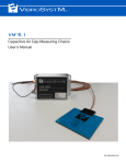
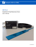
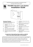
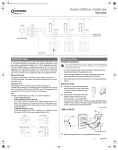
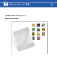
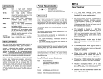
PDA-200™ PARTIAL DISCHARGE ANALYZER UNIT User’s Manual Safety Information The following manual contains information and warnings. They must be followed in order to keep the instrument in a working condition and ensure safe operation. Safety and Electrical Symbols Warning - Danger - Identifies conditions or practices that could cause physical harm or damage the equipment Caution - Identifies conditions or practices that could result in permanent loss of data. Important Information - Must be read and followed Electronics common - not linked to earth ground Shield connection location Safety Precautions Warning - Danger • • • • • • • • • • Caution Although most instruments and accessories are normally used at non-hazardous voltage levels, hazardous conditions may be present in some situations; This product is intended to be used by qualified operators and maintenance personnel who recognize shock hazards and are familiar with the safety precautions required to avoid possible injury. Carefully read and follow all installation, operation, and maintenance information before using this product; Install and use this instrument only as specified in this manual or the protection provided by this instrument might be impaired; Do not use this instrument in wet environments; When in doubt that safety protection has been impaired, make this instrument inoperative and secure it against any unintended operation; Have this instrument serviced by qualified service personnel only; Never remove the cover or open the case without first turning off the main power source; Never operate this instrument with the cover removed or the case open; Use caution when working with voltages above 30 VAC RMS or 42 VDC. These voltage levels can cause shock hazards; Do not operate this instrument around explosive gas, vapor, or dust. The VibroSystM logo, PDA-200™, and ZOOM® are registered trademarks or trademarks of VibroSystM Inc. This manual is provided solely for guidance. VibrosystM Inc. takes no responsibility or liability for any damage caused by accidents, improper installation or misuse. Liability is limited to the repair and/or replacement of defective products. VibroSystM Inc. 2727 Jacques-Cartier E. Blvd, Longueuil, QC, Canada J4N 1L7 | Phone: 450 646-2157 | U.S. Toll-free Line: 800 663-8379 Email: [email protected] | www.vibrosystm.com 22 2 Copyright ©VibroSystM Inc. 2014 PDA-200 Partial Discharge Analyzer - User’s Manual FOA Series Fiber Optic Accelerometer - User’s Manual Copyright © VibroSystM Inc., 2013 l FOA Series Fiber FOA OpticSeries Accelerometer Fiber Optic - User’s Accelerometer Manual - User’s Manual P/N 9477-25I2A-110 TABLE OF CONTENTS 1. GENERAL DESCRIPTION................................................................................................... 5 1.1 Description .................................................................................................................................................. 1.2 Main Unit Interventions .............................................................................................................................. 1.3 Overview of the PDA-200’s Main Components......................................................................................... 5 5 5 2. INSTALLATION OVERVIEW ............................................................................................... 6 2.1 Preliminary Considerations Before Installing the PDA-200 in a Rack or Enclosure ................................. 2.2 Cabling the PDA-200.................................................................................................................................. 2.2.1 Power Input ........................................................................................................................................ 2.2.2 Ethernet Port....................................................................................................................................... 2.2.3 Relay drivers ...................................................................................................................................... 2.2.4 PD Inputs (Channels 1 to 6) ............................................................................................................... 6 6 6 7 7 8 3. USING THE PDA-200........................................................................................................... 9 3.1 LED Indicators............................................................................................................................................ 3.2 USB Port ..................................................................................................................................................... 3.3 Maintenance ................................................................................................................................................ 3.3.1 Cleaning ............................................................................................................................................. 9 9 9 9 4. GENERAL SPECIFICATIONS ............................................................................................. 11 l FOA Series Fiber - User’s Manual Copyright © VibroSystM Inc., Accelerometer 2013 FOA Series Fiber OpticOptic Accelerometer - User’s Manual Partial Discharge Analyzer Manual FOA Series FiberPDA-200 Optic Accelerometer - User’s- User’s Manual 33 4l Copyright PDA-200 Partial Discharge Analyzer - User’s Manual FOA Series Fiber Accelerometer - User’s Manual © VibroSystM Inc., 2013 FOA Series Fiber OpticOptic Accelerometer - User’s Manual FOA Series Fiber Optic Accelerometer - User’s Manual 4 1. GENERAL DESCRIPTION 1.1 Description The PDA-200 is a high speed, multi-channel data acquisition unit used for analyzing very high frequency signals from continuous partial discharge measurements. The unit receives the signals from 6 epoxy mica couplers. When combined with the ZOOM® software suite, the entire system is designed to monitor rotating machines and take measurements at specified intervals or upon defined events. Measurement results can be displayed in real time or on demand for analysis purposes. The ZOOM PDA200 is an optional firmware package that can be added to the ZOOM Platform software to allow partial discharge measurement. 1.2 Main Unit Interventions • Couplers must be installed on high voltage output circuits at appropriate locations; • The PDA-200’s protection box must be installed within 10m of couplers; • Coaxial cables must be routed and protected from the couplers to the protection box; • The Ethernet cable must be routed and protected from the protection box to the VSM Server; • A main AC power cable is required for a protection box equipped with a VibroSystM power panel. 1.3 Overview of the PDA-200’s Main Components USB l FOA Series Fiber - User’s Manual Copyright © VibroSystM Inc., Accelerometer 2013 FOA Series Fiber OpticOptic Accelerometer - User’s Manual Relay Drivers with LED Status Indicators Ethernet 6 PD Inputs Power Input Partial Discharge Analyzer Manual FOA Series FiberPDA-200 Optic Accelerometer - User’s- User’s Manual 55 2. INSTALLATION OVERVIEW Although it is normally delivered pre-cabled in a 19" rack and part of a complete system, the PDA-200 acquisition unit can also be ordered separately as an addition to an existing installation. 2.1 Preliminary Considerations Before Installing the PDA-200 in a Rack or Enclosure The following guidelines will help you plan your equipment rack configuration: • • • • • • • Allow sufficient clearance around the rack or enclosure for maintenance; Make sure the internal temperature inside the enclosure does not exceed 60°C [140°F]; Cables must be kept away from an electrical noise source, power lines and fluorescent lighting fixtures; Keep signal cables separated from power cables; The unit must be kept away from electrically conductive dust, water or moisture; The PDA-200’s design conforms to the requirements of various 19-inch rack standards. Do not install on a structure which is subjected to vibrations. If vibrations cannot be avoided, anti-vibration mounts are mandatory. 2.2 Cabling the PDA-200 USB Ethernet (RJ45) 24 Vdc 2.2.1 Power Input Mechanical characteristics Panel header with threaded flange Mating plug with screw flange Recommended wire size Phoenix Contact MCV 1.5/3-GF-3.81 (male) Phoenix Contact MC 1.5/3-STF-3.81 (female) 1.5 - 0.5 mm2 [16 - 20 AWG] Electrical characteristics Input voltage range Power consumption 24 VDC ± 15% 35 W 6l Copyright PDA-200 Partial Discharge Analyzer - User’s Manual FOA Series Fiber Accelerometer - User’s Manual © VibroSystM Inc., 2013 FOA Series Fiber OpticOptic Accelerometer - User’s Manual FOA Series Fiber Optic Accelerometer - User’s Manual 6 Caution • • The grounding terminal is essential to provide better efficiency against ESD and EMI perturbations; To ensure protection, the chassis grounding wire must be of a heavier or equal gauge than the grounding wire associated with the AC input. 2.2.2 Ethernet Port Mechanical characteristics Receptacle Cable type RJ-45 CAT6-E Electrical characteristics Protocol Communication speed TCP/IP 100/1000 Base-T TYPICAL RELAY DRIVER CONNECTIONS 2.2.3 Relay drivers Mechanical characteristics Vertical header with threaded flange Phoenix Contact MCV 1.5/5-GF-3.81 (male) Mating plug with screw flange Phoenix Contact MC 1.5/5-STF-3.81 (female) Recommended wire size 0.5 - 0.35 mm2 [20-22 AWG] Electrical characteristics Input Voltage Input Current System OK Channels OK l < ±30 V < 25 mA Driver is closed when the system is operating properly. Driver is opened when a malfunction occurs. Driver is opened when all channels are functional. Driver is closed when at least one channel is found defective. FOA Series Fiber - User’s Manual Copyright © VibroSystM Inc., Accelerometer 2013 FOA Series Fiber OpticOptic Accelerometer - User’s Manual Partial Discharge Analyzer Manual FOA Series FiberPDA-200 Optic Accelerometer - User’s- User’s Manual 77 2.2.4 PD Inputs (Channels 1 to 6) Mechanical characteristics Receptacle SMA connector (female) Electrical characteristics Voltage input range Bandwidth Input impedance 150 kHz to 270 MHz 10 k typical Recommended coupler type Epoxy mica 80 pF ± 10 V 8l Copyright PDA-200 Partial Discharge Analyzer - User’s Manual FOA Series Fiber Accelerometer - User’s Manual © VibroSystM Inc., 2013 FOA Series Fiber OpticOptic Accelerometer - User’s Manual FOA Series Fiber Optic Accelerometer - User’s Manual 8 3. USING THE PDA-200 3.1 LED Indicators Upon each startup, LED indicators light up in the following colors: • • SYSTEM OK CHANNELS OK Yellow Yellow After the startup sequence, the LED indicators change color as follow: • SYSTEM OK Turns Green when the system is powered up and operating properly. Turns Orange when a system component malfunction occurs, such as a firmware malfunction or a network connection error. Flashes Yellow when files are copied from a USB key, and turns Yellow once the operation is completed. • CHANNELS OK Turns Green after firmware has completed booting and all measuring chains are confirmed as functional. Remains Green as long as all measuring chains are functional. Turns Orange when at least one measuring chain looses the carrying signal. 3.2 USB Port The USB port allows connection of a portable storage device to update a firmware. Refer to the ZOOM Installation Guide for details on the update procedure. Important Information • • U3 USB smart drives are not compatible with the PDA-200’s operating system; Apart from this restriction, any portable USB flash drive formatted to FAT32 may be used. 3.3 Maintenance 3.3.1 Cleaning Clean the exterior of the PDA-200 only. Do not apply cleaner directly on the unit or allow liquids to spill or enter the unit. l FOA Series Fiber - User’s Manual Copyright © VibroSystM Inc., Accelerometer 2013 FOA Series Fiber OpticOptic Accelerometer - User’s Manual Partial Discharge Analyzer Manual FOA Series FiberPDA-200 Optic Accelerometer - User’s- User’s Manual 99 10 PDA-200 Partial Discharge Analyzer - User’s Manual FOA Series Fiber Accelerometer - User’s Manual l FOA Copyright © VibroSystM Inc., 2013 Series Fiber OpticOptic Accelerometer - User’s Manual FOA Series Fiber Optic Accelerometer - User’s Manual 10 1 4. GENERAL SPECIFICATIONS PD Inputs Communication • Number of Inputs 6 • Ethernet • Input Impedance 10 k Protocol TCP/IP • Recommended Coupler Type Epoxy Mica 80 pF Speed 100/1000 Base-T Acquisition Specifications Power Requirements • Line Frequency 50 to 60 Hz • Voltage 24 Vdc ±15% • Voltage Range ±2.5 mV to ±10 V Max ± 200 V (Spike < 200 μsec) • Consumption 35 W • Dynamic Range 70 dB • Frequency Range Connection • Power Input 3-Pos. Removable Terminal Block Band 1 150 kHz to 1.04 MHz • Ethernet RJ-45 Band 2 1.04 MHz to 3.15 MHz • PD Inputs SMA Connector (Female) Band 3 3.15 MHz to 7.38 MHz • USB Port Type A, Female Band 4 7.38 MHz to 16.83 MHz • Relay Drivers Band 5 16.83 MHz to 33.16 MHz 5-Pos. Removable Terminal Block Band 6 33.16 MHz to 66.83 MHz Environment Band 7 66.83 MHz to 133.2 MHz • Temperature Range Band 8 133.2 MHz to 266.8 MHz Overall 150 kHz to 266.8 MHz Operation 0 to 60°C [32 to 140°F] Storage -20 to 80°C [-4 to 176°F] Measurement Types with ZOOM • Humidity Up to 95%, Non-Condensing • Partial Discharge Detection Scatter Plots and Trending • Protection Rating IP20 • Fault Matching Diagnostic Pattern Categorization • EMI Detection Continuous Status Indicators and Outputs • SYSTEM OK Indicator Green/Orange LED Relay Driver Bipolar FET* Physical Characteristics • Casing Material 5U High, 19“ Rack-Mount, NEMA 1 Steel, Zinc-plated (±30 V max. / 25 mA max.) • CHANNEL OK Indicator Green/Orange LED Relay Driver Bipolar FET* (±30 V max. / 25 mA max.) *FET: Field Effect Transistor l FOA Series Fiber - User’s Manual Copyright © VibroSystM Inc., Accelerometer 2013 FOA Series Fiber OpticOptic Accelerometer - User’s Manual Partial Discharge Analyzer Manual FOA Series FiberPDA-200 Optic Accelerometer - User’s- User’s Manual 11 11 1 Complete System Overview PDA-200 ACQUISITION UNIT (Inside Protection Box) VSM SERVER WITH ZOOM SOFTWARE SUITE EPOXY MICA COUPLER* (Up to 6) COAXIAL CABLE** CAT6 CABLE POWER PANEL (AC with Filter Shown) *Coupler positioning is in accordance with commonly accepted installation practices. **For maximum system performance, the protection box must be installed within 10 m [33 ft] of the couplers. Optional Power Panels • AC with filter to 24 Vdc, 4 A (100-240 Vac, 50-60 Hz); • Universal to 24 Vdc, 4A (100-240 Vac, 50-60 Hz, 105-250 Vdc). Dimensions USB Relay Drivers with LED Status Indicators Ethernet Power Input 6 PD Inputs 12 PDA-200 Partial Discharge Analyzer - User’s Manual FOA Series Fiber Accelerometer - User’s Manual l FOA Copyright © VibroSystM Inc., 2013 Series Fiber OpticOptic Accelerometer - User’s Manual FOA Series Fiber Optic Accelerometer - User’s Manual 12 1