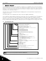
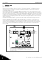
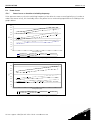
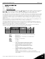
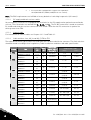
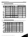
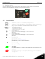
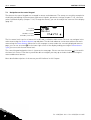
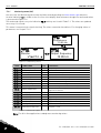
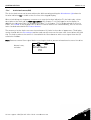
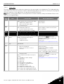
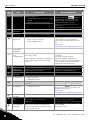
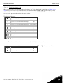
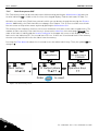
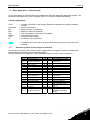
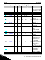
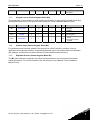
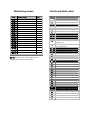
1
NX Variable Speed Drives
Installation Manual
Issue 3/A
Author:
RTW/VACON
Issue:
3/A
Date:
04/07/2006
Part Number:
TG200434
Copyright:
Trend Control Systems Limited
Horsham, W. Sussex
All rights reserved. This manual contains proprietary information that is
protected by copyright. No part of this manual may be reproduced, transcribed,
stored in a retrieval system, translated into any language or computer language,
or transmitted in any form whatsoever without the prior consent of the
publisher.
Manufactured for and on behalf of the Environmental and Combustion
Controls Division of Honeywell Technologies Sàrl, Ecublens, Route du Bois
37,Switzerland by its Authorized Representative, Trend Control Systems
Limited
For information contact:
Trend Control Systems Limited
P.O. Box 34
Horsham
W. Sussex RH12 2YF
NOTICE: Trend Control Systems Limited makes no representations or
warranties of any kind whatsoever with respect to the contents hereof and
specifically disclaims any implied warranties of merchantability or fitness for
any particular purpose. Trend Control Systems Limited shall not be liable for
any errors contained herein or for incidental or consequential damages in
connection with the furnishing, performance or use of this material. Trend
Control Systems Limited reserves the right to revise this publication from time
to time and make changes in the content hereof without obligation to notify
any person of such revisions or changes.
Contents
CONTENTS
1
2
2.1
2.2
TREND NX DRIVES................................................................... 3
INSTALLATION ON A TREND SYSTEM................................. 5
Connections................................................................................ 7
2.1.1 Basic Connections ......................................................... 7
2.1.2 Using NXNI or NXIP interfaces...................................... 8
Sample Applications ................................................................... 12
2.2.1 NX drive - stand alone ................................................... 12
2.2.2 NX drive stand alone with start/stop contactor .............. 13
2.2.3 NX drive with Direct On line bypass .............................. 14
2.2.4 NX drive with parallel motor operations ......................... 15
2.2.5 NX drive with duty/standby motors ................................ 16
3
GENERAL INSTALLATION (USER’S MANUAL)
4
BASIC APPLICATION
5
STANDARD APPLICATION
6
QUICK REFERENCE
NX Variable Speed Drives Installation Manual TG200434 Issue 3/A 04/07/2006
1
Contents
This page is intentionally left blank
2
NX Variable Speed Drives Installation Manual TG200434 Issue 3/A 04/07/2006
Trend NX Drives
1 TREND NX DRIVES
Trend Supply the following range of NX Variable Speed Drives
All Trend NX drives have the following options:
Nominal mains voltage 380 to 500 Vac 3 phase supply; alphanumeric keypad
fitted; 6 pulse connection, air cooled, 2 standard boards (Basic I/O Board
OPTA1, Basic Relay Board OPTA2).
3.5 A to 300 A units are standard performance with standard EMC emission
level, EN61800-3 + A11 (industrial level) 1st environment restricted
distribution
385 A and 460 A units are high performance with standard EMC emission
level, EN61800-3 + A11 2nd environment.
Note that VACON codes are described on page 14 of attached NX User’s
manual (Part 3)
NX Variable Speed Drives Installation Manual TG200434 Issue 3/A 04/07/2006
3
Trend NX Drives
Part 3, 4, 5 of this manual are produced by VACON as follows:
Part 3: VACON NX User’s Manual (vd00701s)
(for VACON NX APPLICATION MANUAL referred to on the
contents page, see NX Drives Application Manual TE200443, VACON
NX Frequency Converters ‘All in One’ APPLICATION MANUAL,
ud885f).
Part 4: NX Basic Application from section 1 of NX Drives Application
Manual TE200443, (VACON NX Frequency Converters ‘All in One’
APPLICATION MANUAL, ud885f).
Part5: NX Standard Application from section 2 of NX Drives
Application Manual TE200443, (VACON NX Frequency Converters
‘All in One’ APPLICATION MANUAL, ud885f).
Part 6: Quick Reference from VACON NX QUICK HELP (quick_help
p701s) pages, 2, 4, 5 & 6.
Additional information is a available as follows:
NX Variable Speed Drives Data Sheet TA200433. This includes a full
description of the functionality.
NX Variable Speed Drives Application Manual TE200443 (VACON NX
Frequency Converters ‘All in One’ APPLICATION MANUAL, ud885f). This
includes descriptions of all the applications supplied with the drives.
4
NX Variable Speed Drives Installation Manual TG200434 Issue 3/A 04/07/2006
Installation on a Trend System
2 INSTALLATION ON A TREND SYSTEM
The Trend NX drive must be installed in a vertical position. It can be mounted
on a wall or in an enclosure using four screws or bolts. The cooling airflow to
the drive must not be blocked in any way; recirculation of air inside the
enclosure should be avoided.
The following tables give clearance and cooling air requirements:
Sizes FR4 to FR9 (3 A to 300 A)
Current
(A)
3 to 12
16 to 31
35 to 61
72 to 105
140 to 205
261 to 300
A (mm)
20
20
30
80
20
50
A2
(mm)
150
-
B (mm)
C (mm)
D (mm)
20
20
20
80
80
80
100
120
160
300
300
400
50
60
80
100
200
250(350*)
air
(m3/h)
70
190
425
425
650
1300
Key:
A: free space on both sides of
drive
A2: clearance needed on both
sides of drive for fan change
(without disconnecting motor
cables).
B: distance between two drives or
distance to cabinet wall
C: free space above drive
D: free space below drive (350*
refers to minimum distance for fan
change)
If several units are mounted above
each other the required space
between them equals C+D. Also
the outlet air used for cooling the
lower unit must be directed away
from the inlet air to be used by the
upper unit.
NX Variable Speed Drives Installation Manual TG200434 Issue 3/A 04/07/2006
5
Installation on a Trend System
Size FR10 (385 A and 460 A)
Current
(A)
385 to
400
H1
(mm)
W1
(mm)
D1
(mm)
2275
600
600
3
Cooling air required: 2600 m /h
Overload protection of the supply cable should be considered (e.g. fuses). The
use of shielded motor cables is recommended; they should be routed as far
away from other cables as possible, and cross other cables at right angles. The
motor cable shield should be grounded at both the NX drive and at the motor.
The installation involves:
mount the controller in position
connect mains cable
connect motor cable
check mains and motor cable insulation
connect control cable
check quality and quantity of cooling air
check inside of drive for condensation
set up links on basic board NX/OPTA1
check all start/stop switches connected to I/O are at stop
switch on power to drive
configure the drive (e.g. using the keypad)
perform run test without motor
commission with motor connected
6
NX Variable Speed Drives Installation Manual TG200434 Issue 3/A 04/07/2006
Installation on a Trend System
2.1
2.1.1
Connections
Basic Connections
RS232
(connection to keypad or PC)
cable ACC/NX/RS2432PC
9Way D type Male
9Way D type Female
Control Connections
Connect according to application e.g connections
to IQ Controller for Basic application
Speed
Analogue Output
0 to 10 V
AIA1+
AIA1-
AO 0 V
On/Off
Digital Output
DO NO
Digital Input
DIn SIG
+24 V
DO COM
Running
Optional
external filter
Digital Input
DIn+1 SIG
DIn+1 COM
IQ Controller
RO1 NO
RO1 COM
DIn COM
Fault
RO2 NO
RO2 COM
NX Drive
Note that the NXNI interface connects the drive directly to
the IQ system current loop Lan, and enables the drive to be
monitored and controlled by IQ2 (IC Comms) and
Supervisors (Text Comms). The NXIP fulfils a similar
function for an Ethernet connection and IQ3 controllers.
Power Connections
3 phase mains supply motor connection
NX Variable Speed Drives Installation Manual TG200434 Issue 3/A 04/07/2006
7
Installation on a Trend System
2.1.2
Using NXNI or NXIP interfaces
Trend NXNI or NXIP
NXNI
T- T+ R- R+
NXIP
RJ45 Connector
100 m
(109 yds)
RJ45 Connector
IQ System
current loop
connection
Ethernet
hub/switch
The NXNI (NX network interface) or NXIP (NX Ethernet interface) can be
fitted inside the NX drive to provide an IQ System network connection. The
NXIP contains a watchdog strategy that will use default values in the event
that text communications are not received from a controller or supervisor
within a given time.
The following parameters are available for text communications or intercontroller communications (IC Comms):
8
NX Variable Speed Drives Installation Manual TG200434 Issue 3/A 04/07/2006
Installation on a Trend System
Sensors
Sensor
Label ($)
Units (%)
Description
1
O-P Motor Speed
rpm
Operating motor speed
2
O-P Power kW
kW
Operating power to motor
3
O-P Frequency
Hz
Operating frequency to motor
4
O-P Current
Amps
Operating current to motor
5
Motor Torque
%
Percentage of rated drive torque
6
O-P Supply Voltage
VAC
Operating voltage to motor
7
Unit Internl Tmp
degC
8
Min Frequency
Hz
9
Max Frequency
Hz
10
Preset Freq 1
Hz
Internal drive temperature
Minimum frequency setting defines minimum
speed
Maximum frequency setting defines maximum
speed
Preset frequency (speed) 1, see I8
11
Preset Freq 2
Hz
Preset frequency (speed) 2, see I9
12
Nominal Current
Amps
Current rating of motor
13
Nominal Power
kW
Power rating of motor
14
Nominal Voltage
Volt
Voltage rating of motor
15
Nominal Speed
rpm
16
O-P Power %
%
17
Active Fault
Code
Speed rating of motor
Operating power, percentage of drive power
rating
A code defining an active fault condition
18
MWh Total Cntr
MWh
Cumulative MWh to motor (non-resettable)
19
MWh Trip Cntr
MWh
Cumulative MWh to motor (resettable via keypad)
20
Hours Run
Hrs
Number of hours drive has been powered
Digital Inputs
Description
Digital
Input
Label ($)
Required
State (R)
1
Motor Status
O
2
Motor Available
O
3
4
Fault status
Warning Status
O
O
5
DI1
O
I=Status of external digital input 1. Input
function can be programmed
6
DI2
O
I=Status of external digital input 2. Input
function can be programmed
7
DI3
O
I=Status of external digital input 3. Input
function can be programmed
8
Preset 1 Select
O
9
Preset 2 Select
O
10
Fault Reset IP
O
I= motor on, O= motor off
I=motor connected and not in fault O=not
available
I=fault present, motor stopped
I=fault present programmed to generate
warning only, motor continues to run
I=Preset frequency 1 (S10) has been
selected
I=Preset frequency 2 (S11) has been selected
I=Fault reset input is I, resetting the fault
condition
NX Variable Speed Drives Installation Manual TG200434 Issue 3/A 04/07/2006
9
Installation on a Trend System
Knobs
Knob
Label ($)
1
Demand
2*
Failure
Demand
Units
(%)
%
Top
(T)
100
-
0
Limit
Bottom
(B)
0
Limit
Description
Defines required speed in
terms of percentage of
frequency range between
minimum and maximum
frequency (S8 to S9)
Defines required speed if
the
watchdog
strategy
detects that the demand
value
has
not
been
received.
0
Switches
Switch
Label ($)
1
Command Signal
Description
I switches motor on, O switches motor off
2
3*
Fault Reset
Watchdog
Set to I to reset the fault
Starts the timer in the watchdog strategy when
set to 1, when set to 0 timer is reset. If watchdog
strategy is being used this must be set to 0 at a
regular interval less than the on delay set in
watchdog strategy (default 600s).
4*
Watchdog Enable
5*
Fail Run Mode
Enables/disables
the
watchdog
strategy.
1=enabled, 0=disabled.
The run mode used (i.e. motor on/off) if the
watchdog strategy detects that the command
signal has not been received.
* These parameters are used by the watchdog strategy only available in NXIP
Note that the Knobs and Switches provide control of the motor from the network
(e.g. from a controller by IC Comms).
Display and Directory Modules: (e.g. for use by NDP)
Directory
Label
1
Operation
2
10
Display
Item
Label
Units
S3
O-P Frequency
Hz
S4
O-P Current
Amps
S2
O-P Power kW
kW
I2
Motor Available
I3
Fault Status
S17
Active Fault
W2
Fault Reset
I8
Preset 1 Select
I9
Preset 2 Select
NX Variable Speed Drives Installation Manual TG200434 Issue 3/A 04/07/2006
Installation on a Trend System
Plotting Channels
Channel
Sensor
1
S2
Label
O-P Power kW
2
S3
O-P Frequency
3
S4
O-P Current
Full details of the NXNI are provided in the NXNI Data Sheet, TA200544. Its
installation is covered in the NXNI Installation Instructions, TG200543.
Full details of the NXIP are provided in the NXIP Data Sheet, TA200826. Its
installation is covered in the NXIP Installation Instructions, TG200827.
NX Variable Speed Drives Installation Manual TG200434 Issue 3/A 04/07/2006
11
Installation on a Trend System
2.2
Sample Applications
2.2.1
NX drive - stand alone
In this application the NX drive is supplied with 3 phase via a fuse and an
isolating contact. An alternative is to use a fused switch (shown dotted). The
start/stop contact connects terminals 6 to 8 to start the drive. The speed is set
by the voltage signal at terminals 2, 3.
The motor local isolator has an early break, late make contact in the circuit
between terminals 6 and 8. If the motor isolator is operated, the early break
ensures that the drive output is stopped before isolating the motor, and the
motor is connected before the drive output commences.
12
NX Variable Speed Drives Installation Manual TG200434 Issue 3/A 04/07/2006
Installation on a Trend System
2.2.2
NX drive stand alone with start/stop contactor
This application is similar to the previous, but now there is a start/stop
contactor which stops the drive by both isolating the supply to the drive, and
breaking the connection between terminals 6 and 8 (via contacts C1). The
isolating switch will isolate both the drive and the start/stop contactor.
NX Variable Speed Drives Installation Manual TG200434 Issue 3/A 04/07/2006
13
Installation on a Trend System
2.2.3
NX drive with Direct On line bypass
In this application the drive can be bypassed.
An Emergency Stop (ES) contact has been added in series with the start/stop
contact which will disconnect the C1 coil, and isolate the drive, and switch it
off via the C1 contacts.
The bypass is operated by a 3 position switch (NX, Off, Bypass).
In the NX position, the time delay contactor, T1, will cause C2 to operate. C2
is mechanically interlocked to C3 so that as C2 closes C3 cannot close and
stops the motor supply being connected back to the input. Closing C2 also
powers up C1 which puts power on the drive and starts it via terminals 6 and 8.
In the Off position, both drive and bypass are isolated so the motor is off.
In the Bypass position, C3 operates which bypasses the drive via C3 contact
and stops the supply being fed back to the Drive via the open C2 contact.
Another open C2 contact isolates the C1 coil and stops the drive starting. If the
overload contact operates, it opens the bypass, and also de-energises the C3
coil which drops out the C3 bypass contact.
14
NX Variable Speed Drives Installation Manual TG200434 Issue 3/A 04/07/2006
Installation on a Trend System
2.2.4
NX drive with parallel motor operations
In this application, the drive operates 2 motors which are separately isolated by
two local isolators (L1 and L2). Since the NX drive is supplying both motors
in parallel it cannot individually protect them, so each drive has an in-built
thermistor relay which will operate if the motor overheats. TH1 will deenergise C1, and TH2 will de-energise C2. As the start connection between
terminals 6 and 8 consists of C1 and C2 in series, if either motor is isolated or
overheats, both motors will be switched off.
NX Variable Speed Drives Installation Manual TG200434 Issue 3/A 04/07/2006
15
Installation on a Trend System
2.2.5
NX drive with duty/standby motors
This system drives 2 motors in duty/standby e.g. they are both mounted on a
common drive shaft.
The motors are controlled by a three position switch (Motor 1, Off, Motor 2).
If Motor 1 is selected, then closing the start contact will energise the C1 coil
which will connect terminals 6 and 8 together, and connect the output of the
drive to motor 1.
Since the C1 and C2 motor contacts are mechanically interlocked so that
closing one prevents the other from closing; closing C1 will stop C2 closing
and switch off motor 2.
In the Off position neither motor can operate.
Since the circuit is symmetrical, in the Motor 2 position, motor 2 is switched
on and motor 1 is switched off.
The local isolators (L1, L2) will isolate the appropriate motor.
Note that since the C1 and C2 contacts are in parallel across terminals 6 and
8, the motors can operate independently unlike example 1.2.4 above where
they can only operate together.
16
NX Variable Speed Drives Installation Manual TG200434 Issue 3/A 04/07/2006
2 • vacon
AT LEAST THE 10 FOLLOWING STEPS OF THE START-UP QUICK GUIDE MUST BE PERFORMED
DURING THE INSTALLATION AND COMMISSIONING.
IF ANY PROBLEMS OCCUR, PLEASE CONTACT YOUR LOCAL DISTRIBUTOR.
Start-up Quick Guide
1.
Check that the delivery corresponds to your order, see Chapter 1.
2.
Before taking any commissioning actions read carefully the safety instructions in
Chapter 1.
3.
Before the mechanical installation, check the minimum clearances around the unit and
check the ambient conditions in Chapter 5.
4.
Check the size of the motor cable, mains cable, mains fuses and check the cable
connections, read Chapters 6.1.1.1 to 6.1.1.5.
5.
Follow the installation instructions, see Chapter 6.1.5.
6.
Control connections are explained in Chapter 6.2.1.
7.
If the Start-Up wizard is active, select the language of the keypad and the application you
want to use and confirm by pressing the Enter button. If the Start-Up wizard is not
active, follow the instructions 7a and 7b.
7a. Select the language of the keypad from the Menu M6, page 6.1. Instructions on using
the keypad are given in Chapter 7.
7b. Select the application you want to use from the Menu M6, page 6.2. Instructions on
using the keypad are given in Chapter 7.
8.
All parameters have factory default values. In order to ensure proper operation, check
the rating plate data for the values below and the corresponding parameters of
parameter group G2.1.
•
•
•
•
•
nominal voltage of the motor
nominal frequency of the motor
nominal speed of the motor
nominal current of the motor
motor cosϕ
All parameters are explained in the All in One Application Manual.
9.
Follow the commissioning instructions, see Chapter 8.
10. The Vacon NX_ Frequency Converter is now ready for use.
Vacon Plc is not responsible for the use of the frequency converters against
the instructions.
Tel. +358 (0)201 2121 • Fax +358 (0)201 212 205
vacon • 3
CONTENTS
VACON NXS/P USER’S MANUAL
INDEX
1
SAFETY
2
EU DIRECTIVE
3
RECEIPT OF DELIVERY
4
TECHNICAL DATA
5
INSTALLATION
6
CABLING AND CONNECTIONS
7
CONTROL KEYPAD
8
COMMISSIONING
9
FAULT TRACING
24-hour support +358 (0)40 837 1150 • Email: [email protected]
4 • vacon
ABOUT THE VACON NXS/P USER'S MANUAL
Congratulations for choosing the Smooth Control provided by Vacon NX Frequency Converters!
The User's Manual will provide you with the necessary information about the installation, commissioning
and operation of Vacon NX Frequency Converters. We recommend that you carefully study these
instructions before powering up the frequency converter for the first time.
This manual is available in both paper and electronic editions. We recommend you to use the electronic
version if possible. If you have the electronic version at your disposal you will be able to benefit from the
following features:
The manual contains several links and cross-references to other locations in the manual which makes it
easier for the reader to move around in the manual, to check and find things faster.
The manual also contains hyperlinks to web pages. To visit these web pages through the links you must
have an internet browser installed on your computer.
Tel. +358 (0)201 2121 • Fax +358 (0)201 212 205
vacon • 5
Vacon NXS/P User's Manual
Index
Document code: ud00701S
Date: 7.12.2005
1.
1.1
1.2
1.3
1.4
2.
SAFETY ............................................................................................................................... 7
Warnings ..........................................................................................................................................7
Safety instructions ...........................................................................................................................7
Earthing and earth fault protection ................................................................................................8
Running the motor...........................................................................................................................8
EU DIRECTIVE .................................................................................................................... 9
2.1 CE marking ......................................................................................................................................9
2.2 EMC directive ...................................................................................................................................9
2.2.1 General ................................................................................................................................9
2.2.2 Technical criteria.................................................................................................................9
2.2.3 Vacon frequency converter EMC classification ..................................................................9
2.2.4 Manufacturer's declaration of conformity .......................................................................10
3.
3.1
3.2
3.3
3.4
4.
4.1
4.2
4.3
4.4
RECEIPT OF DELIVERY ..................................................................................................... 14
Type designation code ...................................................................................................................14
Storage ...........................................................................................................................................15
Maintenance...................................................................................................................................15
Warranty.........................................................................................................................................15
TECHNICAL DATA............................................................................................................. 16
Introduction....................................................................................................................................16
Power ratings.................................................................................................................................18
4.2.1 Vacon NX_5 – Mains voltage 380—500 V ..........................................................................18
4.2.2 Vacon NX_6 – Mains voltage 525—690 V ..........................................................................19
4.2.3 Vacon NX_2 – Mains voltage 208—240 V ..........................................................................20
Brake resistor ratings ...................................................................................................................21
Technical data................................................................................................................................23
5.
INSTALLATION ................................................................................................................. 25
5.1 Mounting ........................................................................................................................................25
5.2 Cooling ...........................................................................................................................................35
5.2.1 FR4 to FR9 .........................................................................................................................35
5.2.2 Standalone units (FR10 to FR12) ......................................................................................36
5.3 Power losses..................................................................................................................................37
5.3.1 Power losses as function of switching frequency ............................................................37
6.
CABLING AND CONNECTIONS ......................................................................................... 41
6.1 Power unit ......................................................................................................................................41
6.1.1 Power connections ............................................................................................................41
6.1.1.1 Mains and motor cables .............................................................................................41
6.1.1.2 DC supply and brake resistor cables.........................................................................42
6.1.1.3 Control cable ..............................................................................................................42
6.1.1.4 Cable and fuse sizes, NX_2 and NX_5, FR4 to FR9 ...................................................42
6.1.1.5 Cable and fuse sizes, NX_6, FR6 to FR9 ....................................................................43
6.1.1.6 Cable and fuse sizes, NX_5, FR10 to FR12 ................................................................43
6.1.1.7 Cable and fuse sizes, NX_6, FR10 to FR12 ................................................................44
6.1.2 Understanding the power unit topology ...........................................................................44
6.1.3 Changing the EMC protection class..................................................................................45
6.1.4 Mounting of cable accessories .........................................................................................47
24-hour support +358 (0)40 837 1150 • Email: [email protected]
6 • vacon
6.1.5 Installation instructions ....................................................................................................49
6.1.5.1 Stripping lengths of motor and mains cables ...........................................................50
6.1.5.2 Vacon NX frames and installation of cables..............................................................51
6.1.6 Cable selection and unit installation in accordance with the UL standards..................59
6.1.7 Cable and motor insulation checks ..................................................................................59
6.2 Control unit ....................................................................................................................................60
6.2.1 Control connections ..........................................................................................................61
6.2.1.1 Control cables.............................................................................................................62
6.2.1.2 Galvanic isolation barriers .........................................................................................62
6.2.2 Control terminal signals ...................................................................................................63
6.2.2.1 Digital input signal inversions....................................................................................64
6.2.2.2 Jumper selections on the OPT-A1 basic board .........................................................65
7.
CONTROL KEYPAD ........................................................................................................... 67
7.1 Indications on the Keypad display .................................................................................................67
7.1.1 Drive status indications.....................................................................................................67
7.1.2 Control place indications ..................................................................................................68
7.1.3 Status LEDs (green – green – red) ...................................................................................68
7.1.4 Text lines ...........................................................................................................................68
7.2 Keypad push-buttons.....................................................................................................................69
7.2.1 Button descriptions ...........................................................................................................69
7.3 Navigation on the control keypad..................................................................................................70
7.3.1 Monitoring menu (M1) .......................................................................................................72
7.3.2 Parameter menu (M2) .......................................................................................................73
7.3.3 Keypad control menu (M3) ................................................................................................75
7.3.3.1 Selection of control place...........................................................................................75
7.3.3.2 Keypad reference .......................................................................................................76
7.3.3.3 Keypad direction .........................................................................................................76
7.3.3.4 Stop button activated..................................................................................................76
7.3.4 Active faults menu (M4).....................................................................................................77
7.3.4.1 Fault types ..................................................................................................................78
7.3.4.2 Fault codes .................................................................................................................79
7.3.4.3 Fault time data record................................................................................................83
7.3.5 Fault history menu (M5) ....................................................................................................84
7.3.6 System menu (M6).............................................................................................................85
7.3.6.1 Language selection ....................................................................................................87
7.3.6.2 Application selection ..................................................................................................87
7.3.6.3 Copy parameters ........................................................................................................88
7.3.6.4 Parameter comparison ..............................................................................................90
7.3.6.5 Security .......................................................................................................................91
7.3.6.6 Keypad settings ..........................................................................................................93
7.3.6.7 Hardware settings ......................................................................................................94
7.3.6.8 System info .................................................................................................................96
7.3.7 Expander board menu (M7)............................................................................................. 100
7.4 Further keypad functions ............................................................................................................100
8.
COMMISSIONING............................................................................................................ 101
8.1 Safety............................................................................................................................................101
8.2 Commissioning of the frequency converter................................................................................101
9.
FAULT TRACING ............................................................................................................. 103
Tel. +358 (0)201 2121 • Fax +358 (0)201 212 205
SAFETY
1.
vacon • 7
SAFETY
ONLY A COMPETENT ELECTRICIAN MAY CARRY OUT
THE ELECTRICAL INSTALLATION
1.1
Warnings
1
2
3
4
5
WARNING
6
7
8
9
1.2
The Vacon NX frequency converter is meant for fixed installations only.
Do not perform any measurements when the frequency converter is
connected to the mains.
Do not perform any voltage withstand tests on any part of Vacon NX.
There is a certain procedure according to which the tests shall be performed. Ignoring this procedure may result in damaged product.
The frequency converter has a large capacitive leakage current.
If the frequency converter is used as a part of a machine, the machine
manufacturer is responsible for providing the machine with a main
switch (EN 60204-1).
Only spare parts delivered by Vacon can be used.
The motor starts at power-up if the start command is 'ON'. Furthermore,
the I/O functionalities (including start inputs) may change if parameters,
applications or software are changed. Disconnect, therefore, the motor if
an unexpected start can cause danger.
Prior to measurements on the motor or the motor cable, disconnect the
motor cable from the frequency converter.
Do not touch the components on the circuit boards. Static voltage discharge may damage the components.
Safety instructions
1
2
3
4
5
The components of the power unit of the frequency converter are live
when Vacon NX is connected to mains potential. Coming into contact
with this voltage is extremely dangerous and may cause death or severe injury. The control unit is isolated from mains potential.
The motor terminals U, V, W and the DC-link/brake resistor terminals
are live when Vacon NX is connected to mains, even if the motor is not
running.
After disconnecting the frequency converter from the mains, wait until
the fan stops and the indicators on the keypad go out (if no keypad is
attached see the indicators on the cover). Wait 5 more minutes before
doing any work on Vacon NX connections. Do not even open the cover
before this time has expired.
The control I/O-terminals are isolated from the mains potential. However, the relay outputs and other I/O-terminals may have a dangerous
control voltage present even when Vacon NX is disconnected from mains.
Before connecting the frequency converter to mains make sure that the
Vacon NX front and cable covers are closed.
24-hour support +358 (0)40 837 1150 • Email: [email protected]
1
8 • vacon
1.3
SAFETY
Earthing and earth fault protection
The Vacon NX frequency converter must always be earthed with an earthing conductor connected to the
earthing terminal
.
The earth fault protection inside the frequency converter protects only the converter itself against earth
faults in the motor or the motor cable. It is not intended for personal safety.
Due to the high capacitive currents present in the frequency converter, fault current protective switches
may not function properly.
1.4
Running the motor
Warning symbols
For your own safety, please pay special attention to the instructions marked with the following symbols:
= Dangerous voltage
= General warning
WARNING
= Hot surface – Risk of burn
HOT SURFACE
MOTOR RUN CHECK LIST
Before starting the motor, check that the motor is mounted properly and
ensure that the machine connected to the motor allows the motor to be
started.
Set the maximum motor speed (frequency) according to the motor and
the machine connected to it.
Before reversing the motor make sure that this can be done safely.
1
2
WARNING
3
4
5
1
Make sure that no power correction capacitors are connected to the
motor cable.
Make sure that the motor terminals are not connected to mains
potential.
Tel. +358 (0)201 2121 • Fax +358 (0)201 212 205
EU DIRECTIVE
2.
EU DIRECTIVE
2.1
CE marking
vacon • 9
The CE marking on the product guarantees the free movement of the product within the EEA (European
Economic Area).
Vacon NX frequency converters carry the CE label as a proof of compliance with the Low Voltage Directive
(LVD) and the Electro Magnetic Compatibility (EMC). The company SGS FIMKO has acted as the Competent
Body.
2.2
2.2.1
EMC directive
General
The EMC Directive provides that the electrical apparatus must not excessively disturb the environment it is
used in, and, on the other hand, it shall have an adequate level of immunity toward other disturbances from
the same environment.
The compliance of Vacon NX frequency converters with the EMC directive is verified with Technical Construction Files (TCF) checked and approved by SGS FIMKO, which is a Competent Body. The Technical
Construction Files are used to authenticate the comformity of Vacon frequency converters with the Directive because such a large-sized product family is impossible to be tested in a laboratory environment and
because the combinations of installation vary greatly.
2.2.2
Technical criteria
Our basic idea was to develop a range of frequency converters offering the best possible usability and costefficiency. EMC compliance was a major consideration from the outset of the design.
Vacon NX frequency converters are marketed throughout the world, a fact which makes the EMC requirements of customers different. As far as the immunity is concerned, all Vacon NX frequency converters are
designed to fulfil even the strictest requirements, while as regards the emission level, the customer may
want to upgrade Vacon's already high ability to filter electro-magnetic disturbances.
2.2.3
Vacon frequency converter EMC classification
Vacon NX frequency converters are divided into four classes according to the level of electromagnetic
disturbances emitted. The EMC class of each product is defined in the type designation code.
Class C (NX_5, FR4 to FR6, Protection class IP54):
Frequency converters of this class fulfil the requirements of the product standard EN 61800-3+A11 for
the 1st environment (unrestricted distribution) and the 2nd environment.
The emission levels correspond to the requirements of EN 61000-6-3.
Note: If the protection class of the frequency converter is IP21, the requirements of Class C are fulfilled
only as far as the conducted emissions are concerned.
Class H:
Vacon NX_5 frequency converters (FR4 to FR9) and NX_2 frequency converters (FR4 to FR6) have been
designed to fulfil the requirements of the product standard EN 61800-3+A11 for the 1st environment
restricted distribution and the 2nd environment.
The emission levels correspond to the requirements of EN 61000-6-4.
Class L (NX_6 FR6 to FR9 only):
Provides filtering for the 2nd environment, restricted distribution according to EN 61800-3+A11.
24-hour support +358 (0)40 837 1150 • Email: [email protected]
2
10 • vacon
EU DIRECTIVE
Class T:
The T-class converters have a smaller earth leakage current and are intended to be used with IT supplies
only. If they are used with other supplies no EMC requirements are complied with.
Class N:
The drives of this class do not provide EMC emission protection. This kind of drives are mounted in
enclosures. External EMC filtering is usually required to fulfil the EMC emission requirements.
All Vacon NX frequency converters fulfil all EMC immunity requirements (standards EN 61000-6-1,
EN 61000-6-2 and EN 61800-3+A11).
Warning: This is a product of the restricted sales distribution class according to IEC 61800-3. In a
domestic environment this product may cause radio interference in which case the user may be
required to take adequate measures.
Note: For changing the EMC protection class of your Vacon NX frequency converter from class H or L to
class T, please refer to the instructions given in Chapter 6.1.3.
2.2.4
Manufacturer's declaration of conformity
The following pages present the Manufacturer's Declarations of Conformity assuring the compliance of
Vacon frequency converters with the EMC-directives.
2
Tel. +358 (0)201 2121 • Fax +358 (0)201 212 205
EU DIRECTIVE
vacon • 11
EU DECLARATION OF CONFORMITY
We
Manufacturer's name:
Vacon Oyj
Manufacturer's address:
P.O.Box 25
Runsorintie 7
FIN-65381 Vaasa
Finland
hereby declare that the product
Product name:
Vacon NXS/P Frequency converter
Model designation:
Vacon NXS/P 0003 5…. to 0520 5….
has been designed and manufactured in accordance with the following
standards:
Safety:
EN50178 (1997), EN60204-1 (1996)
EN 60950 (3rd edition 2000, as relevant)
EMC:
EN61800-3 (1996)+A11(2000), EN 61000-6-2
(2001), EN 61000-6-4 (2001)
and conforms to the relevant safety provisions of the Low Voltage Directive
(73/23/EEC) as amended by the Directive (93/68/EEC) and EMC Directive
89/336/EEC.
It is ensured through internal measures and quality control that the product
conforms at all times to the requirements of the current Directive and the
relevant standards.
In Vaasa, 22nd of November, 2005
Vesa Laisi
President
The year the CE marking was affixed:
24-hour support +358 (0)40 837 1150 • Email: [email protected]
2002
2
12 • vacon
EU DIRECTIVE
EU DECLARATION OF CONFORMITY
We
Manufacturer's name:
Vacon Oyj
Manufacturer's address:
P.O.Box 25
Runsorintie 7
FIN-65381 Vaasa
Finland
hereby declare that the product
Product name:
Vacon NXS/P Frequency converter
Model designation:
Vacon NXS/P 0004 6…. to 0416 6….
has been designed and manufactured in accordance with the following
standards:
Safety:
EN50178 (1997), EN60204-1 (1996)
EN 60950 (3rd edition 2000, as relevant)
EMC:
EN61800-3 (1996)+A11(2000), EN 61000-6-2
(2001), EN 61000-6-4 (2001)
and conforms to the relevant safety provisions of the Low Voltage Directive
(73/23/EEC) as amended by the Directive (93/68/EEC) and EMC Directive
89/336/EEC.
It is ensured through internal measures and quality control that the product
conforms at all times to the requirements of the current Directive and the
relevant standards.
In Vaasa, 22nd of November, 2005
Vesa Laisi
President
The year the CE marking was affixed:
2
2003
Tel. +358 (0)201 2121 • Fax +358 (0)201 212 205
vacon • 13
EU DECLARATION OF CONFORMITY
We
Manufacturer's name:
Vacon Oyj
Manufacturer's address:
P.O.Box 25
Runsorintie 7
FIN-65381 Vaasa
Finland
hereby declare that the product
Product name:
Vacon NXS/P Frequency converter
Model designation:
Vacon NXS/P 0004 2…. to 0300 2….
has been designed and manufactured in accordance with the following
standards:
Safety:
EN50178 (1997), EN60204-1 (1996)
EN 60950 (3rd edition 2000, as relevant)
EMC:
EN61800-3 (1996)+A11(2000), EN 61000-6-2
(2001), EN 61000-6-4 (2001)
and conforms to the relevant safety provisions of the Low Voltage Directive
(73/23/EEC) as amended by the Directive (93/68/EEC) and EMC Directive
89/336/EEC.
It is ensured through internal measures and quality control that the product
conforms at all times to the requirements of the current Directive and the
relevant standards.
In Vaasa, 22nd of November, 2005
Vesa Laisi
President
The year the CE marking was affixed:
24-hour support +358 (0)40 837 1150 • Email: [email protected]
2003
2
14 • vacon
3.
RECEIPT OF DELIVERY
RECEIPT OF DELIVERY
Vacon NX frequency converters have undergone scrupulous tests and quality checks at the factory before
they are delivered to the customer. However, after unpacking the product, check that no signs of transport
damages are to be found on the product and that the delivery is complete (compare the type designation of
the product to the code below, Figure 3-1.
Should the drive have been damaged during the shipping, please contact primarily the cargo insurance
company or the carrier.
If the delivery does not correspond to your order, contact the supplier immediately.
In the small plastic bag included in the delivery you will find a silver Drive modified sticker. The purpose of
the sticker is to notify the service personnel about the modifications made in the frequency converter.
Attach the sticker on the side of the frequency converter to avoid losing it. Should the frequency converter
be later modified (option board added, IP or EMC protection level changed), mark the change in the sticker.
3.1
Type designation code
NXS
0000
5
A 2 H 1 SSV A1A20000C3
Option boards; each slot is represented by two characters where:
A = basic I/O board, B = expander I/O board,
C = fieldbus board, D = special board
Hardware modifications; Supply - Mounting - Boards
Sxx = 6-pulse connection (FR4 to FR14)
Bxx = Additional DC-connection (>FR8)
Jxx = FR10...12 stand-alone with main switch and DC-link terminals
xSx = Air-cooled drive
xxS = Standard boards (FR4 to FR8)
xxV = Varnished boards (FR4 to FR8)
xxF = Standard boards (FR9 to FR14)
xxG = Varnished boards (FR9 to FR14)
xxA = Standard boards (FR10 to FR12 standalone drives)
xxB = Varnished boards (FR10 to FR12 standalone drives)
Brake chopper
0 = no brake chopper
1 = internal brake chopper
2 = internal brake chopper and resistor
EMC emission level:
C = fulfils standard EN61800-3+A11, 1st environment (unrestr.)
H = fulfils standard EN61800-3+A11, 1st environment
restricted distribution, 2nd environment
L = fulfils standard EN61800-3+A11, 2nd environment, restr. distr.
T = fulfils standard EN61800-3 for IT networks
N = No EMC emission protection
Enclosure class:
0 = IP00 (FR9 only), 2 = IP21/NEMA 1, 3 = IP21/NEMA 1 (cabinet-mounted)
5 = IP54 (NEMA 12), 7 = IP54/NEMA 12
Control keypad:
A = standard (alpha-numeric)
B = no local control keypad
F = dummy keypad
G = graphic display
Nominal mains voltage (3-phase):
2 = 208–240Vac, 5 = 380–500Vac, 6 = 525–690Vac (All 3-phase)
Nominal current (low overload)
0007 = 7 A, 0022 = 22 A, 0205 = 205 A etc.
Product range: NXS = standard, NXP = high-performance
Figure 3-1. Vacon NX type designation code
Note: Ask factory for other possible installation combinations.
3
Tel. +358 (0)201 2121 • Fax +358 (0)201 212 205
RECEIPT OF DELIVERY
3.2
vacon • 15
Storage
If the frequency converter is to be kept in store before use make sure that the ambient conditions are
acceptable:
Storing temperature
Relative humidity
–40…+70°C
<95%, no condensation
If the storage time exceeds 12 months the electrolytic DC capacitors need to be charged with caution.
Therefore, such a long storage time is not recommended.
3.3
Maintenance
In normal conditions, Vacon NX frequency converters are maintenance-free. However, we recommend to
clean the heatsink with compressed air whenever necessary.
The cooling fan can easily be changed if necessary.
It may also be necessary to check the tightening torques of terminals at certain intervals.
3.4
Warranty
Only manufacturing defects are covered by the warranty. The manufacturer assumes no responsibility for
damages caused during or resulting from transport, receipt of the delivery, installation, commissioning or
use.
The manufacturer shall in no event and under no circumstances be held responsible for damages and
failures resulting from misuse, wrong installation, unacceptable ambient temperature, dust, corrosive
substances or operation outside the rated specifications.
Neither can the manufacturer be held responsible for consequential damages.
The Manufacturer's time of warranty is 18 months from the delivery or 12 months from the commissioning
whichever expires first (Vacon Warranty Terms).
The local distributor may grant a warranty time different from the above. This warranty time shall be
specified in the distributor's sales and warranty terms. Vacon assumes no responsibility for any other
warranties than that granted by Vacon itself.
In all matters concerning the warranty, please contact first your distributor.
24-hour support +358 (0)40 837 1150 • Email: [email protected]
3
16 • vacon
TECHNICAL DATA
4.
TECHNICAL DATA
4.1
Introduction
Figure 4-1 presents the block diagram of the Vacon NX frequency converter. The frequency converter
mechanically consists of two units, the Power Unit and the Control Unit. Pictures of the mechanical
assemblage on pages 51 to 58.
The three-phase AC-choke (1) at the mains end together with the DC-link capacitor (2) form an LC-filter,
which, again, together with the diode bridge produce the DC-voltage supply to the IGBT Inverter Bridge (3)
block. The AC-choke also functions as a filter against High Frequency disturbances from the mains as well
as against those caused by the frequency converter to the mains. It, in addition, enhances the waveform of
the input current to the frequency converter. The entire power drawn by the frequency converter from the
mains is active power.
The IGBT Inverter Bridge produces a symmetrical, 3-phase PWM-modulated AC-voltage to the motor.
The Motor and Application Control Block is based on microprocessor software. The microprocessor
controls the motor basing on the information it receives through measurements, parameter settings,
control I/O and control keypad. The motor and application control block controls the motor control ASIC
which, in turn, calculates the IGBT positions. Gate drivers amplify these signals for driving the IGBT
inverter bridge.
Brake resistor*
Power
module
Brake
Chopper*
1)
Mains
Integrated input module
3)
IGBT
Inverter Current
Sensors
Rectifier
3~
L1
L2
Motor
=
=
L3
U Output
V filter
2)
3~
Charg.res.
W
Fan
Power
Supply
Measurements
PE
Gate
Drivers
Control
Keypad
RS 232
Control
module
Control
I/O
Control
I/O
Motor and
Application
Control
Control
I/O
Motor
Control
ASIC
Control
I/O
Control
I/O
NK4_1
*The brake resistor can be installed internally in sizes FR4 to FR6 (NX_2 and NX_5). In all other
frames of voltage classes NX_2 and NX_5, as well as in all frames of all other voltage classes, the
brake resistor is available as option and installed externally.
Brake chopper belongs to the standard equipment in sizes FR4 to FR6, while in greater sizes
(FR7 to FR9) it is optional.
Figure 4-1. Vacon NX block diagram
4
Tel. +358 (0)201 2121 • Fax +358 (0)201 212 205
TECHNICAL DATA
vacon • 17
The control keypad constitutes a link between the user and the frequency converter. The control keypad is
used for parameter setting, reading status data and giving control commands. It is detachable and can be
operated externally and connected via a cable to the frequency converter. Instead of the control keypad,
also a PC can be used to control the frequency converter if connected through a similar cable.
You can have your frequency converter equipped with a control I/O board which is either isolated (OPT-A8)
or not isolated (OPT-A1) from the ground.
The basic control interface and the parameters (the Basic Application) are easy to use. If a more versatile
interface or parameters are required, a more suitable application can be chosen from the "All in One+"
Application Package. See the "All in One+" Application Manual for more information on the different
applications.
A brake resistor is available as internal option for frames FR4 to FR6 of voltage classes NX_2 and NX_5. In
all other frames of voltage classes NX_2 and NX_5, as well as in all frames of all other voltage classes, the
brake resistor is available as option and installed externally.
Optional I/O expander boards that increase the number of inputs and outputs to be used are also available.
For closer information, contact the Manufacturer or your local distributor (see back cover).
24-hour support +358 (0)40 837 1150 • Email: [email protected]
4
18 • vacon
4.2
TECHNICAL DATA
Power ratings
4.2.1
Vacon NX_5 – Mains voltage 380—500 V
High overload = Max current IS, 2 sec/20 sec, 150% overloadability, 1 min/10 min
Following continuous operation at rated output current, 150 % rated output current (IH)
for 1 min, followed by a period of load current less than rated current, and of such
duration that the r.m.s output current, over the duty cycle, does not exceed rated
output current (IH)
Low overload = Max current IS, 2 sec/20 sec, 110% overloadability, 1 min/10 min
Following continuous operation at rated output current, 110% rated output current (IL)
for 1 min, followed by a period of load current less than rated current, and of such
duration that the r.m.s output current, over the duty cycle, does not exceed rated
output current (IL)
All sizes are available as IP21/NEMA1. Sizes FR4 to FR9 are additionally available as IP54/NEMA12.
Mains voltage 380-500 V, 50/60 Hz, 3~
Frequency
converter
type
NX 0003 5
NX 0004 5
NX 0005 5
NX 0007 5
NX 0009 5
NX 0012 5
NX 0016 5
NX 0022 5
NX 0031 5
NX 0038 5
NX 0045 5
NX 0061 5
NX 0072 5
NX 0087 5
NX 0105 5
NX 0140 5
NX 0168 5
NX 0205 5
NX 0261 5
NX 0300 5
NX 0385 5
NX 0460 5
NX 0520 5
NX 0590 5
NX 0650 5
NX 0730 5
NX 0820 5
NX 0920 5
NX 1030 5
Loadability
Low
Motor shaft power
High
380V supply
500V supply
50%
10%
Rated
Max
50%
10%
50%
10%
Rated
continuous overload continuous overload current overload overload overload overload
50°C
40°C
IS
50°C
40°C
current IL current current IH current
P(kW)
P(kW)
P(kW)
(A)
(A)
P(kW)
(A)
(A)
3.3
4.3
5.6
7.6
9
12
16
23
31
38
46
61
72
87
105
140
170
205
261
300
385
460
520
590
650
730
820
920
1030
3.6
4.7
6.2
8.4
9.9
13.2
17.6
25.3
34
42
51
67
79
96
116
154
187
226
287
330
424
506
572
649
715
803
902
1012
1133
2.2
3.3
4.3
5.6
7.6
9
12
16
23
31
38
46
61
72
87
105
140
170
205
245
300
385
460
520
590
650
730
820
920
3.3
5.0
6.5
8.4
11.4
13.5
18.0
24.0
35
47
57
69
92
108
131
158
210
255
308
368
450
578
690
780
885
975
1095
1230
1380
4.4
6.2
8.6
10.8
14
18
24
32
46
62
76
92
122
144
174
210
280
336
349
444
540
693
828
936
1062
1170
1314
1476
1656
1.1
1.5
2.2
3
4
5.5
7.5
11
15
18.5
22
30
37
45
55
75
90
110
132
160
200
250
250
315
355
400
450
500
500
0.75
1.1
1.5
2.2
3
4
5.5
7.5
11
15
18.5
22
30
37
45
55
75
90
110
132
160
200
250
250
315
355
400
450
500
1.5
2.2
3
4
5.5
7.5
11
15
18.5
22
30
37
45
55
75
90
110
132
160
200
250
315
355
400
450
500
500
630
710
1.1
1.5
2.2
3
4
5.5
7.5
11
15
18.5
22
30
37
45
55
75
90
110
132
160
200
250
315
355
400
450
500
500
630
Frame
Dimensions and
weight
WxHxD/kg
FR4
FR4
FR4
FR4
FR4
FR4
FR5
FR5
FR5
FR6
FR6
FR6
FR7
FR7
FR7
FR8
FR8
FR8
FR9
FR9
FR10
FR10
FR10
FR11
FR11
FR11
FR12
FR12
FR12
128x292x190/5
128x292x190/5
128x292x190/5
128x292x190/5
128x292x190/5
128x292x190/5
144x391x214/8.1
144x391x214/8.1
144x391x214/8.1
195x519x237/18.5
195x519x237/18.5
195x519x237/18.5
237x591x257/35
237x591x257/35
237x591x257/35
291x758x344/58
291x758x344/58
291x758x344/58
480x1150x362/146
480x1150x362/146
595x2018x602/300
595x2018x602/300
595x2018x602/300
794x2018x602/370
794x2018x602/370
794x2018x602/370
1210x2017x602/600
1210x2017x602/600
1210x2017x602/600
Table 4-1. Power ratings and dimensions of Vacon NX, supply voltage 380—500V.
Note: The rated currents in given ambient temperatures are achieved only when the switching frequency is equal to
or less than the factory default.
Note: The rated currents for FR10 to FR12 are all valid at an ambient temperature of 40 °C.
4
Tel. +358 (0)201 2121 • Fax +358 (0)201 212 205
TECHNICAL DATA
4.2.2
vacon • 19
Vacon NX_6 – Mains voltage 525—690 V
High overload = Max current IS, 2 sec/20 sec, 150% overloadability, 1 min/10 min
Following continuous operation at rated output current, 150 % rated output current (IH)
for 1 min, followed by a period of load current less than rated current, and of such
duration that the r.m.s output current, over the duty cycle, does not exceed rated
output current (IH)
Low overload = Max current IS, 2 sec/20 sec, 110% overloadability, 1 min/10 min
Following continuous operation at rated output current, 110% rated output current (IL)
for 1 min, followed by a period of load current less than rated current, and of such
duration that the r.m.s output current, over the duty cycle, does not exceed rated
output current (IL)
All sizes are available as IP21/NEMA1 or IP54/NEMA12.
Mains voltage 525-690 V, 50/60 Hz, 3~
Frequency
converter
type
NX 0004 6
NX 0005 6
NX 0007 6
NX 0010 6
NX 0013 6
NX 0018 6
NX 0022 6
NX 0027 6
NX 0034 6
NX 0041 6
NX 0052 6
NX 0062 6
NX 0080 6
NX 0100 6
NX 0125 6
NX 0144 6
NX 0170 6
NX 0208 6
NX 0261 6
NX 0325 6
NX 0385 6
NX 0416 6
NX 0460 6
NX 0502 6
NX 0590 6
NX 0650 6
NX 0750 6
NX 0820 6
Loadability
Low
Motor shaft power
High
690V supply
Rated
10%
50%
Rated
continuous overload continuous overload
current IL current current IH current
(A)
(A)
(A)
(A)
4.5
5.5
7.5
10
13.5
18
22
27
34
41
52
62
80
100
125
144
170
208
261
325
385
416
460
502
590
650
750
820
5.0
6.1
8.3
11.0
14.9
19.8
24.2
29.7
37
45
57
68
88
110
138
158
187
229
287
358
424
458
506
552
649
715
825
902
3.2
4.5
5.5
7.5
10
13.5
18
22
27
34
41
52
62
80
100
125
144
170
208
261
325
325
385
460
502
590
650
650
4.8
6.8
8.3
11.3
15.0
20.3
27.0
33.0
41
51
62
78
93
120
150
188
216
255
312
392
488
488
578
690
753
885
975
975
575V supply
Max
current
IS
10%
overload
40°C
P(kW)
50%
overload
50°C
P(kW)
10%
overload
40°C
P(hp)
50%
overload
50°C
P(hp)
Frame
Dimensions and
weight
WxHxD/kg
6.4
9.0
11.0
15.0
20.0
27
36
44
54
68
82
104
124
160
200
213
245
289
375
470
585
585
693
828
904
1062
1170
1170
3
4
5.5
7.5
10
15
18.5
22
30
37.5
45
55
75
90
110
132
160
200
250
315
355
400
450
500
560
630
710
800
2.2
3
4
5.5
7.5
10
15
18.5
22
30
37.5
45
55
75
90
110
132
160
200
250
315
315
355
450
500
560
630
630
3.0
3.0
5.0
7.5
11
15
20
25
30
40
50
60
75
100
125
150
150
200
250
300
400
450
450
500
600
650
800
800
2.0
3.0
3.0
5.0
7.5
11
15
20
25
30
40
50
60
75
100
125
150
150
200
250
300
300
400
450
500
600
650
650
FR6
FR6
FR6
FR6
FR6
FR6
FR6
FR6
FR6
FR7
FR7
FR8
FR8
FR8
FR9
FR9
FR9
FR9
FR10
FR10
FR10
FR10
FR11
FR11
FR11
FR12
FR12
FR12
195x519x237/18,5
195x519x237/18,5
195x519x237/18,5
195x519x237/18,5
195x519x237/18,5
195x519x237/18,5
195x519x237/18,5
195x519x237/18,5
195x519x237/18,5
237x591x257/35
237x591x257/35
291x758x344/58
291x758x344/58
291x758x344/58
480x1150x362/146
480x1150x362/146
480x1150x362/146
480x1150x362/146
595x2018x602/300
595x2018x602/300
595x2018x602/300
595x2018x602/300
794x2018x602/370
794x2018x602/370
794x2018x602/370
1210x2017x602/600
1210x2017x602/600
1210x2017x602/600
Table 4-2. Power ratings and dimensions of Vacon NX, supply voltage 525—690V.
Note: The rated currents in given ambient temperatures are achieved only when the switching frequency is
equal to or less than the factory default.
Note: The rated currents for FR10 to FR12 are all valid at an ambient temperature of 40 °C.
24-hour support +358 (0)40 837 1150 • Email: [email protected]
4
20 • vacon
4.2.3
TECHNICAL DATA
Vacon NX_2 – Mains voltage 208—240 V
High overload = Max current IS, 2 sec/20 sec, 150% overloadability, 1 min/10 min
Following continuous operation at rated output current, 150 % rated output current (IH)
for 1 min, followed by a period of load current less than rated current, and of such
duration that the r.m.s output current, over the duty cycle, does not exceed rated
output current (IH)
Low overload = Max current IS, 2 sec/20 sec, 110% overloadability, 1 min/10 min
Following continuous operation at rated output current, 110% rated output current (IL)
for 1 min, followed by a period of load current less than rated current, and of such
duration that the r.m.s output current, over the duty cycle, does not exceed rated
output current (IL)
All sizes are available as IP21/NEMA1 or IP54/NEMA12.
Mains voltage 208-240 V, 50/60 Hz, 3~
Frequency
converter
type
Loadability
Low
Motor shaft power
High
230V supply
Rated
Max
10%
50%
10%
Rated
continuous overload continuous overload current overload
IS
40°C
current IL current current IH current
(A)
(A)
P(kW)
(A)
(A)
NX 0004 2
NX 0007 2
NX 0008 2
NX 0011 2
NX 0012 2
NX 0017 2
NX 0025 2
NX 0031 2
NX 0048 2
NX 0061 2
NX 0075 2
NX 0088 2
NX 0114 2
NX 0140 2
NX 0170 2
NX 0205 2
NX 0261 2
NX 0300 2
4.8
6.6
7.8
11
12.5
17.5
25
31
48
61
75
88
114
140
170
205
261
300
5.3
7.3
8.6
12.1
13.8
19.3
27.5
34.1
52.8
67.1
83
97
125
154
187
226
287
330
3.7
4.8
6.6
7.8
11
12.5
17.5
25
31
48
61
75
88
105
140
170
205
245
5.6
7.2
9.9
11.7
16.5
18.8
26.3
37.5
46.5
72.0
92
113
132
158
210
255
308
368
7.4
9.6
13.2
15.6
22
25
35
50
62
96
122
150
176
210
280
336
349
444
0.75
1.1
1.5
2.2
3
4
5.5
7.5
11
15
22
22
30
37
45
55
75
90
208-240V
supply
50%
10%
50%
overload overload overload
50°C
40°C
50°C
P(kW)
P(hp)
P(hp)
0.55
0.75
1.1
1.5
2.2
3
4
5.5
7.5
11
15
22
22
30
37
45
55
75
1
1.5
2
3
5
7.5
10
15
20
25
30
40
50
60
75
100
125
0.75
1
1.5
2
3
5
7.5
10
15
20
25
30
40
50
60
75
100
Frame
Dimensions and
weight
WxHxD/kg
FR4
FR4
FR4
FR4
FR4
FR5
FR5
FR5
FR6
FR6
FR7
FR7
FR7
FR8
FR8
FR8
FR9
FR9
128x292x190/5
128x292x190/5
128x292x190/5
128x292x190/5
128x292x190/5
144x391x214/8,1
144x391x214/8,1
144x391x214/8,1
195x519x237/18,5
195x519x237/18,5
237x591x257/35
237x591x257/35
237x591x257/35
291x758x344/58
291x758x344/58
291x758x344/58
480x1150x362/146
480x1150x362/146
Table 4-3. Power ratings and dimensions of Vacon NX, supply voltage 208—240V.
Note: The rated currents in given ambient temperatures are achieved only when the switching frequency is
equal to or less than the factory default.
4
Tel. +358 (0)201 2121 • Fax +358 (0)201 212 205
TECHNICAL DATA
4.3
vacon • 21
Brake resistor ratings
Mains voltage 380-500 V, 50/60 Hz, 3~
NX 0003 5
Max. brake current
[I]
12
Resistor nom
[ohm]
63
NX 0105 5
Max. brake current
[I]
111
Resistor nom.
[ohm]
6.5
NX 0004 5
12
NX 0005 5
12
63
NX 0140 5
222
3.3
63
NX 0168 5
222
3.3
NX 0007 5
NX 0009 5
12
63
NX 0205 5
222
3.3
12
63
NX 0261 5
222
3.3
NX 0012 5
12
63
NX 0300 5
222
3.3
NX 0016 5
12
63
NX 0385 5
570
1,4
NX 0022 5
12
63
NX 0460 5
570
1,4
NX 0031 5
17
42
NX 0520 5
570
1,4
NX 0038 5
35
21
NX 0590 5
855
0,9
NX 0045 5
35
21
NX 0650 5
855
0,9
NX 0061 5
51
14
NX 0730 5
855
0,9
NX 0072 5
111
6.5
NX 0820 5
2 x 570
2 x 1,4
NX 0087 5
111
6.5
NX 0920 5
2 x 570
2 x 1,4
Resistor nom.
[ohm]
7
Converter type
Converter type
Table 4-4. Brake resistor ratings, Vacon NX, supply voltage 380–500V
Mains voltage 525-690 V, 50/60 Hz, 3~
NX 0004 6
Max. brake current
[I]
11
Resistor nom
[ohm]
100
NX 0125 6
Max. brake current
[I]
157.1
NX 0005 6
11
100
NX 0144 6
157.1
7
NX 0007 6
11
100
NX 0170 6
157.1
7
NX 0010 6
11
100
NX 0208 6
157.1
7
NX 0013 6
11
100
NX 0261 6
440.0
2.5
NX 0018 6
36.7
30
NX 0325 6
440.0
2.5
NX 0022 6
36.7
30
NX 0385 6
440.0
2.5
NX 0027 6
36.7
30
NX 0416 6
440.0
2.5
NX 0034 6
36.7
30
NX 0460 6
647.1
1.7
NX 0041 6
61.1
18
NX 0502 6
647.1
1.7
NX 0052 6
61.1
18
NX 0590 6
647.1
1.7
NX 0062 6
122.2
9
NX 0650 6
2 x 440
2 x 2.5
NX 0080 6
122.2
9
NX 0750 6
2 x 440
2 x 2.5
NX 0100 6
122.2
9
NX 0820 6
2 x 440
2 x 2.5
Converter type
Converter type
Table 4-5. Brake resistor ratings, Vacon NX, supply voltage 525–690V
24-hour support +358 (0)40 837 1150 • Email: [email protected]
4
22 • vacon
TECHNICAL DATA
Mains voltage 208-240 V, 50/60 Hz, 3~
NX 0004 2
Max. brake current
[I]
15
Resistor nom
[ohm]
30
NX 0061 2
Max. brake current
[I]
46
Resistor nom.
[ohm]
10
NX 0007 2
15
30
NX 0075 2
148
3.3
NX 0008 2
15
NX 0011 2
15
30
NX 0088 2
148
3.3
30
NX 0114 2
148
NX 0012 2
3.3
15
30
NX 0140 2
296
1.4
NX 0017 2
15
30
NX 0170 2
296
1.4
NX 0025 2
15
30
NX 0205 2
296
1.4
Converter type
Converter type
NX 0031 2
23
20
NX 0261 2
296
1.4
NX 0048 2
46
10
NX 0300 2
296
1.4
Table 4-6. Brake resistor ratings, Vacon NX, supply voltage 208–240V
4
Tel. +358 (0)201 2121 • Fax +358 (0)201 212 205
TECHNICAL DATA
4.4
vacon • 23
Technical data
Mains
connection
Motor
connection
Control
characteristics
Input voltage Uin
Input frequency
Connection to mains
Starting delay
Output voltage
Continuous output
current
Starting current
Output frequency
Frequency resolution
Control method
Switching frequency
(see parameter 2.6.9)
Ambient
conditions
Frequency reference
Analogue input
Panel reference
Field weakening point
Acceleration time
Deceleration time
Braking torque
Ambient operating
temperature
Storage temperature
Relative humidity
Air quality:
- chemical vapours
- mechanical
particles
Altitude
Vibration
EN50178/EN60068-2-6
Shock
EN50178, EN60068-2-27
Enclosure class
208…240V; 380…500V; 525…690V; –15%…+10%
45…66 Hz
Once per minute or less
2 s (FR4 to FR8); 5 s (FR9)
0—Uin
IH: Ambient temperature max. +50°C,
overload 1.5 x IH (1 min./10 min.)
IL: Ambient temperature max. +40°C,
overload 1.1 x IL (1 min./10 min.)
IS for 2 s every 20 s
0…320 Hz (standard); 7200 Hz (special software)
0.01 Hz (NXS); Application dependent (NXP)
Frequency control U/f
Open Loop Sensorless Vector Control
Closed Loop Vector Control (NXP only)
Up to NX_0061: 1…16 kHz; Default: 10 kHz
NX