1
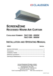
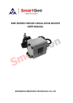
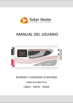
Documentation
GEM 3KW
Power Module
Installation Manual
Revision 3 December 2104
Apollo Solar Electric Limited
Burnt Thorns
Kilsby Lane
Rugby
CV21 4PN
Tel: +44 (0) 1788 511055
Fax: +44 (0) 1788 511078
[email protected]
Contents
Important Safety Information
3
Introduction
4
Power Module Description
5
Power module drawing
5
Power Module DIN Enclosure
6
Typical System Configuration with GEM Power Modules
7
GEM Power Module System Schematic (6KW System)
8
Setting Up the System
9
Compatibility
9
Temperature Control
9
Setting the Output mode
9
Setting the Output Power
9
GEM Set-up Mode
10
Warning
Installation of the GEM system can be carried out by any suitably qualified person. The
installation does not need MCS approval and will not invalidate any part of the MCS approval of
your PV installation.
WARNING : ISOLATE MAINS SUPPLY BEFORE COMMENCING INSTALLATION
INSTALLATION AND CONNECTION SHOULD ONLY BE CARRIED OUT BY A SUITABLY QUALIFIED
PERSON AND IN ACCORDANCE WITH THE CURRENT EDITION OF THE IEE WIRING REGULATIONS.
If in doubt consult a qualified electrician.
Page 2
Safety Information
Warranty
Apollo Solar Electric Ltd. has made every effort to ensure the accuracy of the content of this
manual. However, it is possible that it may contain technical inaccuracies or typographical or
other errors. Apollo Solar Electric Ltd. will assume no liability for any inaccuracy found in this
publication, nor for damages, direct, indirect, incidental, consequential or otherwise, that may
result from such an inaccuracy. Apollo Solar Electric Limited provides this manual “as is”, and
does not issue a warranty of any kind, express or implied.
The information provided in this manual is subject to change without notice. Apollo Solar Electric
Ltd. reserves the right to alter product designs or specifications without notification.
Apollo GEM is a registered trademark of Apollo Solar Electric Ltd.
Important Safety Information
All safety warnings give specific details of the potential danger/warning present and indicate how
to reduce risk of injury, damage and electric shock resulting from improper use of the device.
Carefully observe the following instructions:
• Installation and maintenance must be carried out by a competent person, in compliance with
the manufacturer's instructions, the latest edition of the IEE wiring regulations and local
safety regulations.
If in any doubt, consult a qualified electrician.
• The device must be disconnected from the power supply before carrying out any installation
work.
• A minimum of 50mm clearance must be provided each side of the device to allow adequate
ventilation.
• Regulations require that the device is earthed.
• Do not remove the device cover while the power supply is connected.
• Do not operate the device with the cover removed.
• Do not attempt to repair or replace any part of the device.
• Do not touch the device with any wet part of the body.
• All Maintenance operations must be carried out by a qualified technician.
• This appliance is not suitable for outdoor use.
• The manufacturer accepts no responsibility for any damage or injury caused by improper use
or failure to comply with these instructions.
Page 3
GEM Power Module Installation Manual
Introduction
The standard GEM controller unit is designed to drive a standard 3KW load. This is usually sufficient for
producing domestic hot water from 1-4KWp solar PV systems.
If GEM is to be used in higher power applications such as large hot water accumulators or swimming pool
heating in large PV and/or wind generator installations then a higher output power than 3KW will
probably be needed.
The GEM power modules will increase the GEM output capability to 6KW, 9KW or 12KW.
The GEM controller can support either one, two or three 3KW power modules to give a total power
capability of 12KW.
Note that when the GEM is used with power modules only one GEM output is available. The output
works in conjunction with the power modules to effectively form a single output with a variable power
output from 0-6KW, 0-9KW or 0-12KW depending on the number of power modules used.
The GEM 3KW Power Module
Page 4
GEM Power Module Installation Manual
Power Module Description
The GEM power module is designed to switch a 3KW resistive heating load under the control of the Apollo
GEM controller unit. The power module must not be used for any other application.
The GEM power module measures 100mm L x 35mm W x 78mm H and is designed to mount on a
standard 35mm DIN rail within an electrical enclosure.
The module Heatsink will become quite warm in service and must be mounted in an enclosure large
enough to provide adequate ventilation. In addition the unit when mounted on the DIN rail must have a
minimum 5mm gap between the power module and any other DIN rail mounted item.
A purpose designed DIN rail enclosure for installing up to three GEM power modules together with all
cable terminations etc. is available from Apollo.
Power module drawing
Power ON
Indicator
Output ON
Indicator
Control Input
Neutral
Live Input
Live Output
Page 5
GEM Power Module Installation Manual
Power Module DIN Enclosure
The Apollo GEM Power Module DIN enclosure is shown below.
The enclosure houses up to 3 power modules and includes all necessary terminations for a 6KW to 12KW
GEM system.
Interior of GEM Power Module Enclosure with 2 Power Modules Installed
Page 6
GEM Power
Installation
Module
Manual
Installation Manual
Typical System Configuration with GEM Power Modules
GEM Controller
9KW Water heating system using 2 GEM power Modules
and 3 x 3KW immersion elements
Alternative 9KW Water heating system using 2 GEM power Modules and single
boss 9KW “3-phase” immersion element
Page 7
GEM Power
Installation
Module
Manual
Installation Manual
GEM Power Module System Schematic (6KW System)
GEM
Power
Module
GEM Controller
L N N N L1 L2 L3 E E E
Control Signal To
Power Module 2
(For 9KW Systems)
Control Signal
N
16A Supply 2
L
L
16A Supply 1
N
N
L
L
3KW Immersion 1
N
3KW Immersion 2
Notes:
1.
!Supply 1 and Supply 2 (and supply 3 if 2 power modules are used) must be the same phase!
2.
Each supply must use a minimum 1.5mm CSA supply cable.
3.
Each supply must be protected by a 16A Breaker.
4.
Loads must not exceed 3.5KW per load
Page 8
GEM Power
Installation
Module
Manual
Installation Manual
Setting Up the System
Compatibility
The GEM power modules can only be used with GEM controllers running software version 3.07 or
higher.
Temperature Control
Temperature control can use either the GEM temperature sensor or the built-in immersion
thermostat in immersion heater 1, i.e. the immersion heater element connected directly to the
GEM controller. When the GEM controller senses that the thermostat in immersion heater 1 is up
to temperature it will also turn off the loads on power module 1 (and 2/3).
See the GEM installation manual to information on configuring temperature control and setting
temperatures.
Setting the Output mode
In order to use the external power module(s) the GEM output parameter in the second page of
the installer menu must be set to “Power Module” as shown:
The GEM output mode is set in screen 2 of the installer menu:
Mode: SINGLE UNIT
Output: Power Module
Output 1 Power 6000W
GEM Output mode
setting:
Output: Power Module
Setting the Output Power
The Output 1 power parameter must be set to the total power of the system and will usually be
set to 6000W when 1 power module is installed or 9000W when 2 power modules are installed.
This setting tells GEM what the total system power is but each individual load will be 3KW.
Page 9
GEM Power Module Installation Manual
GEM Set-up Mode
Gem set-up mode is used to program various operating parameters such as the time/date,
enable or disable the optimiser or timer, program the timer on/off times, enter the required
optimiser and timer hot water temperatures etc.
GEM Set-up mode is entered by pressing and holding the set/boost Button
seconds.
for at least 3
Upon entering set-up mode the first of 5 set-up screens are displayed:
•
A setting which can be changed slowly flashes on and off.
•
To change the setting press the UP or DOWN arrow keys.
•
To move to then next setting press the SET key.
•
When the last setting on the screen has been reached pressing
the SET key will advance to the next set-up screen
•
When the last item on the last set-up screen has been reached
the set-up display goes back to the first set-up screen
•
Holding the SET key down at any position in a setup screen provides a shortcut jump to
the next set-up screen without stepping through each item.
•
The changes will be saved and set-up will automatically exit
after no keys are pressed for 30 seconds.
Changeable
Item Flashes
Timer
ENABLED
Optimiser ENABLED
Set Time
Pressing the set
button moves to
the next item
Mon 00:01
Pressing the up
or down buttons
changes the
setting
Page 10
GEM Power
Notes
Installation
Module
Manual
Installation Manual
Page 11