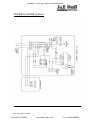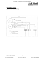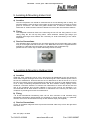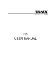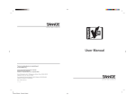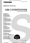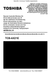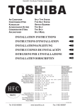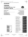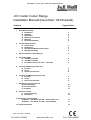
1
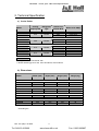
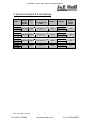
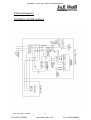
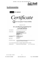
Heronhill - for all your J&E Hall requirements
JCC Cellar Cooler Range
Installation Manual (December ’08 Onwards)
Contents
Page Number
1. Installation & Safety
a) Installation
b) Handling
c) Application
d) Electrical Connection
e) Warranty
f) General Information
2
2
2
2
2
2
2. Technical Specification
a) Cooler Duties
b) Dimensions
c) Pipe Sizes & Maximum Pipe Runs
d) Refrigerant Charge
3
3
4
4
3. Electrical Details & Fuse Ratings
5
4. Wiring Diagrams
a) JCC25E & JCC60E
b) JCC40E & JCC50E
c) All Outdoor Units (J5LC15C – J5LC28C)
6
7
8
5. Locating & Mounting Indoor Unit
a) Location
b) Fixing
c) Service Connections
9
9
9
6. Locating and Mounting Outdoor Unit
a) Location
b) Fixing
c) Service Connections
9
9
9
7. Refrigerant Pipe Connections
a) Pipe Installation
b) Unit Connections
c) Insulation
10
10
10
8. Pressure Testing
a) Pressure Testing
b) Evacuation
10
10
9. Electronic Controller Setup
a) Models - JCC 25E & JCC 60E – Danfoss EKC 101
b) Models – JCC 40E & JCC 50E – Dixell XR 20C
11
11
10. CE Documentation
12
Ref: JCC (IM) 1.12 2008
Tel: 018123 665660
1
www.heronhill.co.uk
Fax: 01823 665807
Heronhill - for all your J&E Hall requirements
1.
Installation & Safety
a) Installation
The units making up the J & E Hall International JCC cellar cooling system must only be installed
by a qualified engineer following the mandatory and local codes of practice
b) Handling
Care must be taken when the units are moved or lifted to ensure that everyone and everything is
safe. When lifting equipment is used, it must be suitable and approved
c) Application
Ensure that the unit is only used for a suitable purpose / application
d) Electrical Connection
Electrical work and connections must be made by authorised electricians in accordance with
mandatory regulations and local codes of practice
e) Warranty
Failure to comply with the manufacturer’s installation instructions could affect the performance of
the unit and invalidate the warranty. Warranty is also subject to the implementation of a planned
service / maintenance agreement
f) General Information
•
All works must be carried out in accordance with manufacturer’s installation and
operating procedures
•
Good working practices must be followed at all times so that mechanical and electrical
hazards are kept to a minimum
•
The equipment has been fitted with covers to prevent access during operation. These
must be kept in place and additional guards fitted where necessary
•
The equipment must be connected to a local external electrical isolator as one is not
supplied fitted to the unit. The rocker switch fitted to the indoor unit is for control isolation
only.
•
Servicing and maintenance must only be carried out by a fully qualified engineer. Before
any work is started, electrically isolate the units to make sure they cannot be switched on
accidentally and allow sufficient time for the isolated parts to come to rest before
removing panels. Electrical isolation switches MUST be labelled to show that they are off
during the servicing and maintenance operations. Care must be taken not to touch
components or pipework which may be hot or cold, for a period after the unit is electrically
isolated
•
After completing any tasks ensure all guards and covers are correctly refitted before
restoring the power to the unit
•
The equipment has been specifically designed to run at low noise levels; but if further
noise reduction is desired, sound and vibration attenuators may be required. For noise
level guidance refer to technical literature, or contact the distributor for advice
Ref: JCC (IM) 1.12 2008
Tel: 018123 665660
2
www.heronhill.co.uk
Fax: 01823 665807
Heronhill - for all your J&E Hall requirements
2. Technical Specification
a) Cooler Duties
Cooling
Capacity kW
Refrigerant
Type
Indoor Unit
Airflow M³/S
Noise Level dB(A)
JCC25E
J5LC15C
2.45
R410a
0.83
N/a
Internal 45
External 30
JCCC40E
J5LC20C
4.05
R410a
0.83
N/a
Internal 45
External 32
JCCC50E
J5LC25C
5.10
R410a
1.11
N/a
Internal 45
External 32
JCC60E
J5LC28C
6.13
R410a
1.11
N/a
Internal 45
External 34
Model
Notes:
1. dB(A) Levels are free field at 10m
2. Duties Quoted @ 12.7ºC db, 10ºC wb internal, 32ºC external
b) Dimensions
Model
Width (mm)
Depth (mm)
Height (mm)
Weight (kg)
JCC25E
J5LC15C
865
700
370*
250
480
540
30
30
JCC40E
J5LC20C
865
855
370*
328
480
648
33
59
JCC50E
J5LC25C
900
855
370*
328
540
750
36
62
JCC60E
J5LC28C
900
855
370*
328
540
750
38
68
* Excluding fan
Ref: JCC (IM) 1.12 2008
Tel: 018123 665660
3
www.heronhill.co.uk
Fax: 01823 665807
Heronhill - for all your J&E Hall requirements
c) Pipe Sizes and Maximum Pipe Runs
Pipe Connection Sizes
Model
Max Pipe Run
Liquid
Gas
Length
Rise
JCC25E
J5LC15C
1/4"
1/4 “
1/2"
1/2"
12m
5m
JCC40E
J5LC20C
1/4”
1/4”
5/8"
1/2"
15m
8m
JCC50E
J5LC25C
1/4"
1/4”
5/8"
5/8"
15m
8m
JCC60E
J5LC28C
3/8"
3/8"
3/4"
5/8"
15m
8m
Notes:
1. J5LC Condensing Units are Pre-Charged for a 7.6m Pipe Run
2. Run Pipework in the same size as the condensing unit connection and
use copper reducers at the evaporator where necessary
d) Refrigerant Charge
•
JCC25E matched with J5LC15C – Pre Charged with 0.83kg R410a
Additional Charge – 20g per metre up to maximum permissible
•
JCC40E matched with J5LC20C – Pre Charged with 1.38kg R410a
Additional Charge – 20g per metre up to maximum permissible
•
JCC50E matched with J5LC25C – Pre Charged with 1.54kg R410a
Additional Charge – 20g per metre up to maximum permissible
•
JCC60E matched with J5LC28C – Pre Charged with 1.80kg R410a
Additional Charge – 50g per metre up to maximum permissible
Ref: JCC (IM) 1.12 2008
Tel: 018123 665660
4
www.heronhill.co.uk
Fax: 01823 665807
Heronhill - for all your J&E Hall requirements
3. Electrical Details & Fuse Ratings
FLA
(Amps)
LRA
(Amps)
2 Core + E
6.04
N/A
24
16
Indoor
2 Core + E
7.61
N/A
27
20
240/1/50
Indoor
2 Core + E
9.03
N/A
32
25
240/1/50
Indoor
2 Core + E
12.82
N/A
65
32
Model
Power
Supply
v/ph/hz
Power
To
JCC25E
J5LC15C
240/1/50
Indoor
JCC40E
J5LC20C
240/1/50
JCC50E
J5LC25C
JCC60E
J5LC28C
Ref: JCC (IM) 1.12 2008
Tel: 018123 665660
Interconnecting
Cable
Fuse
Rating
Amps
5
www.heronhill.co.uk
Fax: 01823 665807
Heronhill - for all your J&E Hall requirements
4.Wiring Diagrams
JCC25E & JCC60E (Indoor)
Ref: JCC (IM) 1.12 2008
Tel: 018123 665660
6
www.heronhill.co.uk
Fax: 01823 665807
Heronhill - for all your J&E Hall requirements
JCC40E & JCC50E (Indoor)
Ref: JCC (IM) 1.12 2008
Tel: 018123 665660
7
www.heronhill.co.uk
Fax: 01823 665807
Heronhill - for all your J&E Hall requirements
All Outdoor Units
(J5LC15C – J5LC28C)
Ref: JCC (IM) 1.12 2008
Tel: 018123 665660
8
www.heronhill.co.uk
Fax: 01823 665807
Heronhill - for all your J&E Hall requirements
5. Locating & Mounting Indoor Unit
a) Location
The JCC Evaporator unit should be mounted level on a load bearing wall or ceiling. The
minimum distance from the floor to the bottom of the unit should be 1.8 metres to ensure
good air convection. The side inlet grilles should have a minimum clearance from
obstruction of 100mm and the minimum clearance in front of the unit should be 1500mm.
b) Fixing
The evaporator should be fixed to the wall using the two off rear fixing holes or to the
ceiling using the two off top fixing holes. 10mm diameter rawbolt type fixings (not
supplied) with large steel washers are necessary for local load bearing of the indoor
evaporator.
c) Service Connections
The refrigerant pipe connections are accessed through the left hand side panel. Cable
entry is on the right hand side of the unit. A 3/4” BSP drain connector is supplied with the
manuals (or cable tied to the fan guard) to be site fitted to the condensate tray.
(Please note the correct way to fit the drain fitting locknut as below):
6. Locating & Mounting Outdoor Unit
a) Location
Install the J5LC condensing unit in such a way that hot air distributed by the unit cannot be
drawn back in again causing a short circuit of hot discharge air. Allow sufficient space around
the unit for maintenance. Ensure that there are no obstructions to the air flow in to or out of
the unit. The location must be well ventilated so that the unit can draw in and distribute plenty
of air to keep condensing temperatures down and thus maintain cooling capacity. There
should be a minimum clearance of 150mm from obstructions to the air inlet at the side and
rear of the condenser and at least 1000mm in front of the unit for air discharge. It is
recommended that at least 500mm clearance is maintained to the service port side of the
condenser to provide good access for maintenance.
b) Fixing
J & E Hall International Condensing units can be floor mounted or wall mounted using
appropriate load bearing wall brackets (not supplied). In areas where noise is a particular
concern, the unit can be mounted securely on anti vibration strips (not supplied).
c) Service Connections
Access to the flared refrigerant service ports and electrical cable entry is from the right hand
side of the unit.
Ref: JCC (IM) 1.12 2008
Tel: 018123 665660
9
www.heronhill.co.uk
Fax: 01823 665807
Heronhill - for all your J&E Hall requirements
7. Refrigerant Pipe Connections
a) Pipe Installation
Run the suction and liquid lines in the appropriately sized refrigeration grade copper tubing as
per the tables in section 2 (c). Pipework should be run in the same size as the connections on
the J5LC Condensing unit.
b) Unit Connections
The outdoor condensing unit connections are terminated in male flare connections as detailed
in table 2 (c). Indoor pipe connections are provided as plain copper tails that may require a
reducing fitting to match the pipework size to the evaporator connection size.
c) Insulation
Use appropriate insulation tubing with a minimum 3/8” thickness on both refrigerant lines.
8. Pressure Testing
a) Pressure Testing
Before evacuating the system it must be tested for any potential leaks. A pressure leak test
should be carried out using oxygen free nitrogen (OFN). NEVER USE OXYGEN FOR
PRESSURE TESTING SYSTEMS. Before starting any pressure testing, ensure the area
surrounding the system is safe, inform relevant personnel and fit warning signs indicating high
pressure testing. Also use correct PPE as required.
A simple procedure for testing is as follows:
1. Pressure system slowly up to 3 bar (45 psi) for 5 minutes and check for any signs of
leakage.
2. Increase pressure slowly up to 10 bar (150 psi) for 5 minutes and check for any signs
of leakage.
3. Increase pressure slowly up to 33 bar (500 psi) and check for any signs of leakage.
Leave system under pressure for 24 hours.
Listen for any possible leaks and check all joints with bubble spray. If any leaks are
discovered, release pressure slowly from system until empty, repair leak and then restart
pressure testing procedure. Never attempt to repair a leak on a pressurized system.
A strength test should also be incorporated according to local regulations.
Once testing has been completed satisfactorily release the pressure from the system
gradually and safely to external atmosphere.
b) Evacuation
After the pressure testing has been completed, the system should be thoroughly evacuated to
reduce the risk of moisture being present. It is recommended that a triple evacuation
procedure is carried out as follows using a suitable vacuum pump, a torr gauge and oxygen
free nitrogen (OFN):
1.
2.
3.
4.
5.
6.
Evacuate system down to 10 torr.
Break the vacuum with OFN to a pressure of 1 bar.
Evacuate the system to 5 torr.
Break the vacuum with OFN to a pressure of 1 bar.
Evacuate system a third time to 2 torr or lower if possible.
Isolate vacuum pump and leave system for 30 minutes and ensure vacuum is held.
Once above has been completed satisfactorily then refrigerant charge can be introduced to
the system.
Ref: JCC (IM) 1.12 2008
Tel: 018123 665660
10
www.heronhill.co.uk
Fax: 01823 665807
Heronhill - for all your J&E Hall requirements
9. Electronic Controller Setup
JCC 25E & JCC 60E – Danfoss EKC 101
a) To check the setpoint
Press both buttons on the controller together. Set temperature is displayed.
b) To change the setpoint
Press both buttons on the controller together. Set temperature is displayed.
Then press either the top button to raise the setpoint or the bottom button to lower the
setpoint. Press both buttons again to save the new setpoint.
c) Manual Defrost
Press and hold the lower button for four seconds. To stop the defrost press and hold the
lower button for a further four seconds.
JCC 40E & JCC 50E – Dixell XR 20C
a) To check the setpoint
Press and immediately release the SET key. The display will show the current set point value.
b) To change the setpoint
Press and hold the SET key for two seconds. The current setpoint value will be displayed and
the Snow LED starts blinking
Press either the
keys within 10 seconds to adjust the setpoint up or down.
To memorise the change press the SET key again
c) Manual Defrost
To start a manual defrost press and hold the DEF key for 2 seconds
d) To lock the Controller
Press and hold both the
keys for more than three seconds. POF will appear on the
controller display. It is not now possible to change the setpoint
To cancel the controller lock, press and hold the same keys for three seconds until PON is
displayed. It is now possible to change the setpoint again
For further details, please contact your J & E Hall International Distributor
Ref: JCC (IM) 1.12 2008
Tel: 018123 665660
11
www.heronhill.co.uk
Fax: 01823 665807
Heronhill - for all your J&E Hall requirements
10. CE Documentation
Ref: JCC (IM) 1.12 2008
Tel: 018123 665660
12
www.heronhill.co.uk
Fax: 01823 665807