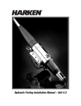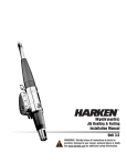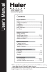
1
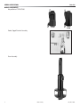
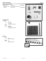
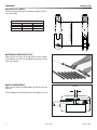
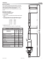
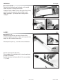
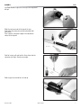
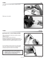
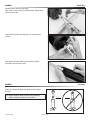
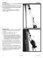
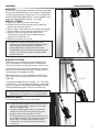
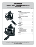
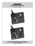
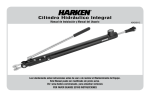
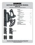
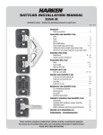
Nautor Furling Installation Manual – C7475/C7550 GENERAL SPECIFICATIONS Parts List ■ MAIN COMPONENTS Halyard Swivel C7475/C7550 C7475 Feeder, Toggle/Terminal Assembly Drum Assembly 2 Nautor Furling C7550 December 2004 GENERAL SPECIFICATIONS Parts List ■ MISCELLANEOUS PARTS Foil Screws Foil Wedges Red Loctite® Torque Tube Screws 5 mm, 8 mm Allen Wrench Super Bonder Prefeeder Blue Loctite® ■ RIGGER PARTS C7475 1 Trim Cap 9 Connectors 1 Long Bottom Connector C7550 1 Trim Cap 10 Connectors 1 Long Bottom Connector ■ FOILS C7475 9 1 C7550 10 1 December 2004 Foils Special Bottom Foil Foils Special Bottom Foil Nautor Furling 3 PREPARATION Headstay Length ■ HEADSTAY CUT LENGTH Subtract the following from the headstay length and cut the stay at that point. 22.2 mm 25.4 mm -30 rod (11.1 mm) 187 mm — -40 rod (12.7 mm) — 201 mm HEADSTAY CUT LENGTH HEADSTAY CUT LENGTH CHART Clevis Pin Size ■ STRINGING CONNECTORS ON STAY Make sure the trim cap is at the top and the correct number of connectors are used. The long bottom connector must be slid on the rod last. ■ ROD COLDHEAD HEIGHT Make sure the length of coldhead does not interfere with the drive pin. 6.5 mm Distance between the collet bottom and the rollpin is 6.5 mm 4 Nautor Furling December 2004 PREPARATION Foil Length ■ FOIL CUT LENGTH Foil cut length is based on pin-to-pin length as measured from center of upper pin (attaches the stay to the mast) to center of lower pin (attaches the furling unit to the boat). Measurement includes the masthead toggle. To check foil length, lay foils alongside stay before cutting top foil. ■ TOP FOIL CUT LENGTH Instructions For Worksheet Below: 1 Fill in total pin-to-pin length. 2 Fill in A length. 3 Add A, B, E, F, G and subtract from total pin-to-pin length. SUM = _________ 4 Choose the number from foil multiplier below closest to, but not greater than, sum from step 3. Fill in D length. 7 x 2133.6 = 8 x 2133.6 = 9 x 2133.6 = 10 x 2133.6 = 11 x 2133.6 = 12 x 2133.6 = 14935.2 17068.8 19202.4 21336.0 23469.6 25603.2 5 Add A, B, D, E, F, G. Subtract from pin-to-pin length for C (top foil length). WORKSHEET: DETERMINE TOP FOIL LENGTH C7475 -30 22.2 mm PIn C7550 -40 25.4 mm PIn A Center of PIN to Bottom of Terminal _____ _____ B Bottom of Terminal to Top of Foil 20 mm 20 mm C Top Foil _____ _____ _____ _____ E Feeder Gap 60 mm 76 mm F Bottom Foil 610 mm 610 mm G Clevis Pin to Foil 661 mm 674 mm _____ _____ DIMENSIONS D __?__ 84” (2133.6 mm) Foils (Quantity) Total Pin-to-Pin Length December 2004 Nautor Furling 5 PREPARATION Foil Length ■ CUTTING TOP FOIL Once you have checked the top foil length, cut the top foil. Deburr and clean all shavings from the foil. Important: Failure to deburr or clean the inside of the foil may cause it to seize to a connector when installing on rod. Rough up the top 1” (25 mm) of the foil using a file or sandpaper. ASSEMBLYFoils ■ ASSEMBLE FOIL Slide the trim cap and one connector to the top of the headstay. Tape other connectors in place or use a pusher wire longer than foil to hold connectors back. Slide top foil to top of stay, screw holes toward the bottom. Coat the connector with red Loctite®. Place a wedge in the indentation with the circular mold mark towards the connector. Push the connector into the top foil until it is recessed about 1 /2” (13 mm). 6 Nautor Furling December 2004 ASSEMBLYFoils Use Super Bonder to glue the trim cap to the roughened foil top. Slide the next connector to the top of the stay. Coat half of the connector and the indentation with red Loctite®. Place a plastic connector wedge in the indentation closest to the top foil. Coat foil screws with red Loctite. Screw them into the connector until tight. Continue assembly. Slide halyard swivel onto foil, tall end up. December 2004 Nautor Furling 7 ASSEMBLYFoils Install feeder screws toward bottom, using blue Loctite® on screws. Slide lower unit onto foils. ASSEMBLY Attach Stay ■ ATTACHING STAY TO TOGGLE/TERMINAL ASSEMBLY Make sure halyard swivel and drum assembly have been slipped on the foils. Slip the rod adapter sleeve onto the rod. Sandwich the nosepiece over the rod and insert into the main body, narrow end first. Jiggle the sleeve or use a small screwdriver to push the nosepiece completely into sleeve. Put several drops of the blue Loctite on the large threads of the stud. Thread the stud into the main body until the slot aligns neatly with the hole in the main body. TIP: Sight through the pin hole to find the optimum thread engagement. Make sure the stud is threaded far enough so the pin is securely seated in the slot, yet not threaded too far to block the pin. 8 Nautor Furling December 2004 ASSEMBLY Attach Stay Hammer the pin into the main body. Clean excess Loctite® from the terminal body. Tape around sleeve to secure pin. Lower drum assembly and slip clevis pin and cotter pin in place. Coat threads of torque tube screws with blue Loctite®. Raise foils and insert foil screws. ASSEMBLY Foil Length Check the clearance between the top of the foil and top terminal. TIP: Check clearance when the unit is on the ground, before raising the headstay into position. December 2004 Nautor Furling 9 ADJUSTMENTS Halyard Wraps ■ HALYARD WRAPS The most serious problem with furling systems occurs when the jib halyard wraps around the headstay foil. Halyard wraps will prevent furling or unfurling and may cause serious damage to the unit and the halyard. In severe cases, halyard wraps may cause headstay loss. To prevent wraps, the halyard must exert a slight pull to the rear. This allows the foils to turn while the halyard remains stationary. ■ PREVENT WRAPS WARNING: The sail must be fitted to the foils before operation. 1 Halyard swivel should be within the top 4” (100 mm) of the foil. 2 Halyard must pull slightly to the rear (8 - 10°). 3 Halyard must be snug, but not too tight. TIP: With the sail raised, walk away from the boat and look at the masthead with binoculars. Use the halyard swivel as a measurement reference. 4” (100 mm) is 1 /3 the length of the swivel. There should be less foil exposed above the swivel than 1/3 of the swivel. 8 - 10° If a halyard wraps, do not force the unit to turn. Attempt to open the sail by alternately furling in and out slightly. If the sail can be unfurled, lower the sail by releasing the jib halyard. Severe halyard wraps can only be cleared by going aloft and freeing the halyard. If the sail will not furl or unfurl, it may be possible to remove the jib sheets and manually wrap the sail around the headstay. Remember: Testing at the dock does not indicate the halyard angle is correct. In wave action, the halyard may wrap if the lead angle is not correct. The 8-10° diverging angle mentioned above is critical. 10 Nautor Furling December 2004 ADJUSTMENTS Pendants/Halyard Restrainer ■ PENDANTS If your sail is not long enough to position the halyard swivel properly, you must add a pendant to the sail. Pendants should be plastic coated wire permanently attached to the sail so the height will be correct. Adjustable length pendants are not acceptable as they might not be adjusted correctly during a sail change. ■ INSTALL A PENDANT 1 Raise the sail, but do not attach tack shackle. 2 Position the halyard swivel correctly near the top of the headstay and secure the halyard. 3 Secure a piece of rope to the sail tack. Lead the line through the tack shackle on the furling drum and tension the sail. 4 Measure the distance from the tack shackle to the sail tack and have a pendant of this length permanently attached to the head of the sail. 5 Repeat this procedure for every jib. TIP: Pendants are used at the head of the sail. Short pendants may be added at the tack to improve visibility under the genoa, but remember that visibility is already improved by shackling to the tack swivel. Tack pendants increase heeling moment by raising the sail plan. You may install pendants at both the head and tack of the sail. ■ HALYARD RESTRAINER To prevent wraps, the jib halyard must pull slightly to the rear. On some boats the halyard sheaves are located too close to the headstay and a halyard restrainer must be used. Use halyard restrainers only when required by the masthead geometry. Restrainers tend to limit sail luff length and may cause problems if not properly installed. Mount the restrainer as high as possible on the face of the mast. Position the restrainer so the foils will not hit it when under load. The restrainer should deflect the halyard 8 - 10°. If the angle is more than 10°, you may experience difficulty in tensioning the sail luff, friction in furling and possible damage to the foils. To decrease deflection angles, shorten the luff of the sail. 8 - 10° TIP: Boats used in charter service should consider using a halyard restrainer, regardless of masthead geometry. ■ HALYARD TENSION The jib halyard should be firm, but not too tight. TIP: The luff foil system supports the sail along its entire length so halyard tension is required only to shape sails, not to support them. Use only enough halyard tension to remove some wrinkles along the luff. Do not tension the halyard enough to cause vertical wrinkles in the luff. Use halyard tension to adjust draft position of the sail to suit sailing conditions. Your halyard should be firm but not tight. If in doubt, release halyard tension. To protect the sail, ease the halyard when the boat is not in use. December 2004 Nautor Furling 11 Corporate Headquarters N15W24983 Bluemound Rd, Pewaukee, WI 53072 USA Telephone: (262) 691-3320 • Fax: (262) 701-5780 Web: www.harken.com • Email: [email protected] Harken Australia Pty, Ltd. 1B Green Street, Brookvale, N.S.W. 2100, Australia Telephone: (61) 2-8978-8666 • Fax: (61) 2-8978-8667 Web: harken.com.au • Email: [email protected] Harken France ZA Port des Minimes, BP 3064, 17032 La Rochelle Cedex 1, France Telephone: (33) 05.46.44.51.20 • Fax: (33) 05.46.44.25.70 Web: harken.fr • Email: [email protected] Harken Italy S.p.A. Via Marco Biagi, 14, 22070 Limido Comasco (CO) Italy Telephone: (39) 031.3523511 • Fax: (39) 031.3520031 Web: harken.it • Email: [email protected] Harken New Zealand, Ltd. 158 Beaumont Street, Westhaven, P.O. Box 90689, Victoria St. West, Auckland 1142, New Zealand Telephone: (64) 9-303-3744 • Fax: (64) 9-307-7987 Web: harken.co.nz • Email: [email protected] Harken Polska SP ZOO ul. Rydygiera 8, budynek 3A, lokal 101, I piętro, 01-793 Warszawa, Poland Tel: +48 22 561 93 93 • Fax: +48 22 839 22 75 Web: harken.pl • Email: [email protected] Harken Sweden AB Main Office and Harken Brandstore: Västmannagatan 81B SE-113 26 Stockholm Sweden Telephone: (46) 0303 61875 • Fax: (46) 0303 61876 Mailing address: Harken Sweden AB, Box 64, SE -440 30 Marstrand Web: harken.se • Email: [email protected] Harken UK, Ltd. Bearing House, Ampress Lane, Lymington, Hampshire S041 8LW, England Telephone: (44) 01590-689122 • Fax: (44) 01590-610274 Web: harken.co.uk • Email: [email protected] Please visit: http://www.harken.com/locator.aspx to locate Harken dealers and distributors M1013/12-04