1
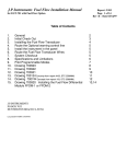
Europa XS Rotax 912S Installation Manual Europa XS Rotax 912S Engine Manual March 2009 Index of Chapters Chapter Page i - 1 Description 1 Engine installation 2 Engine controls 3 Oil tank 4 Exhaust system 5 Cooling duct and coolers 6 Fuel system 7 Engine cowlings 8 Cold air inlet plenum installation 9 Access doors 10 Propeller and spinner 11 Commissioning the engine Annex A Final inspection checklist March 2009 Europa XS Rotax 912S Engine Manual 1. Engine installation Preparation Before starting work on the engine installation read this manual and the Rotax 912S installation manual. There are some delicate parts attached to the engine, notably the ignition triggers, which require care in handling. Instead of installing the engine mounting to the aircraft, then trying to position a heavy engine onto it, the engine mounting should be attached to the engine first. Engine mount fitting There are two mounting frames associated with fitting the engine to the undercarriage frame: the engine itself is fitted to a ring mount which is a Rotax component, and that is fitted to the Europa engine mount, which in turn is fitted to the undercarriage mount. First, if not already done so, fit the Rotax ring mount to the engine using the three M10x35 and one M10x110 bolts. The latter bolt is fitted to the top starboard position. The bolt threads must be coated with Loctite 243, since wire locking is impractical. Then fit the engine mounting frame to the Rotax ring mount using M10 x 110 bolts and M10 Binx nuts. All four bolts should be fitted with the bolt heads aft. The excess length of the bolts will need to be cut off, leaving a minimum of two threads emerging from the end of the nut. Engine installation Mount the engine to the landing gear frame using the rubber mountings. See figure 1. To check the orientation of the engine, set the fuselage level using the port door sill as the reference as usual. Check that the propeller flange is truly vertical. The engine mounting frame has been designed with the engine offset to the right by 1.5°. To check that this offset is correct, clamp a straight edge to the propeller flange horizontally and mark a point 51 cm (20") each side of the engine centre line. Measure the distance from these points, parallel to the aircraft centre line, to the firewall. The difference between the two readings should be 26 mm (1 1/16"). If any correction is found necessary, shim between the landing gear frame and the appropriate cup washer using AN960-516L washers. In order to ensure that the split pin is correctly positioned relative to the castellated nut it will be necessary to use a total of at least 4 washers on each bolt. Any washers that are not needed to act as positioning shims should be placed immediately under the nut. Make a note of where and how many shim washers are used for later reference. Note: The 4 AN5-41 mounting bolts must be tightened fully to compress the rubber anti-vibration mounts (MT04) onto the steel spacers (MT03). Europa XS Rotax 912S Engine Manual March 2009 Page 1 - 1 Caution: It should be noted that before the two ignition leads which come from the ignition box are earthed, the ignition is ”live”. Even though the engine speed must be at least 1200 rpm for the ignition to fire, it would be a sensible precaution to fit the magneto switches before further work is carried out on the engine, or at least temporary earth leads connecting the ignition wires to the engine casing. As it is possible to knock the ignition triggers when installing the engine mounting frame, check the trigger gaps before fitting the engine to the aircraft, as it is difficult to do so afterwards. Propeller drive lugs The engine is normally delivered with the six propeller drive lugs suitable for the Warp Drive ground adjustable propeller supplied loose. These are a light interference fit in the propeller flange, with a relief on the forward part to assist in starting the insertion of them into the flange. To complete the installation it will be necessary to pull them into position using a suitable bolt, nut, and washer, with a spacer tube. Ensure that the drive lugs are fitted with no gap between the back of the propeller flange and the drive lug collar. Page 1 - 2 March 2009 Europa XS Rotax 912S Engine Manual Fig 1. Engine installation. Europa XS Rotax 912S Engine Manual March 2009 Page 1 - 3 INTENTIONALLY BLANK Page 1 - 4 March 2009 Europa XS Rotax 912S Engine Manual 2. Engine controls The Rotax 912 has two independent carburettors, each one providing a fuel/air mixture to one pair of cylinders. The only mechanical controls required for the carburettors are throttle and choke. Although there are two independent throttles and chokes, there is only one throttle and one choke control in the cockpit. Throttle Control A single lever, protruding through a slot in the central spine on top of the central tunnel, provides the pilot with throttle control. The lever is mounted and pivots in a fibreglass housing fixed to the underside of the wheel well, and operates two separate cables. Throttle Lever Housing Drill the holes in the throttle lever housing, as shown in figure 1. Fig 1. Throttle lever housing drilling dimensions. Europa XS Rotax 912S Engine Manual March 2009 Page 2 - 1 Drill also a 4.8 mm hole in each flange for mounting bolts. Open up the hole on the starboard side of the housing to allow a socket spanner through. Assembly Install the cable outers through the two holes in the housing and clamp them in position using the nyloc nut with an AN960-416L washer each side of the fibreglass. Assemble the two cables to the throttle lever according to figure 3 ensuring the end fittings are free to pivot. Thread the cables into the cable outers, then install the lever into the housing as shown in figure 2, adjusting the lever friction as desired. The friction should be sufficient to prevent the carburettor throttle lever spring from opening the throttle automatically, and this can be done after final assembly. Cover the opening in the side of the housing to keep dirt out - a suitably sized rubber grommet would be ideal. Fig 2. Exploded diagram of throttle lever assembly. Page 2 - 2 March 2009 Europa XS Rotax 912S Engine Manual Installation The throttle lever housing should be positioned such that its front face is 380 mm (15") aft of the firewall. For the monowheel aircraft this will ensure clearance with the main wheel top when it is retracted. Mark out and cut a slot for the throttle lever in the spine in the centre tunnel then, checking that full throttle travel is achievable, drill through the flanges for mounting bolts. For ease of installation attach an MS21047-3 anchor nut to the underside of the housing’s flange at each end using TLPK 424 BS rivets then, using AN525-10R10 bolts, secure the housing in place. The front mounting will use an AN970-3 washer, see figure 2, and an AN970-3 washer can be used temporarily to hold the rear of the mounting until it is substituted by the throttle closed stop. Make a handle from wood or any other suitable material for the top of the throttle lever to complete the installation. Slot the throttle cables through the gap between the firewall and the upper mounting members of the landing gear frame, securing them to the frame with tie wraps to prevent chafing. Remove and discard the straight cable-outer receptacle provided on each carburettor and in its place insert the throttle cable’s threaded end. Use one check nut each side of the bracket to clamp the cable-outer in place. The cables may seem excessively long, but this is to allow large bend radii in the engine bay to ensure minimum friction. Insert the cable inner into the nipple on the carburettor throttle lever, which is sprung to its full open position. Setting the throttle lever in the cockpit back about 2-3 cm (1") from its full forward position, screw both nipples tight on the cables. Check for full throttle movement, making any adjustments as required, then seal the open hole in the throttle lever housing to prevent anything thrown up from the wheel from entering. Throttle closed stop The addition of a throttle-closed stop is important to avoid the possibility of excess tension on the throttle cable causing loss of throttle control. Following the method below, prepare a plate, made from 3 mm (1/8”) aluminium, 50 mm (2”) wide. With the throttle closed, and the slow running adjustment correctly set at the carburettors, measure the distance from the rear of the throttle lever, where it protrudes above the top of the tunnel, to the centre of the rear 4.8 mm (3/16”) mounting hole. The plate length will be 6 mm (1/4”) more than this measurement. Drill the plate 6 mm (1/4”) from one end, bond with Redux to the tunnel, and bolt with an AN525-10R10 bolt. Note: You should set the throttle closed stop such that a fully warmed engine idles at 1200 1400 rpm. Although the engine idles more smoothly at 1600 rpm or more, when landing the aircraft you will benefit from minimal residual thrust. Choke Control The two choke control cables are swaged together into the choke operating knob but run in separate outer sleeves which are swaged into a housing. Europa XS Rotax 912S Engine Manual March 2009 Page 2 - 3 Installation Drill a 13 mm (1 2“) diameter hole as low as possible in the back face of the throttle lever spine of the cockpit moulding for the cable outer assembly to go through. See figure 3. Fig 3.Position of choke control. Push the threaded portion of the cable-outer housing through the hole and clamp it in place with the lock washer and knurled nut. Note : As it can be difficult to insert the two cables into their respective outers, remove the plastic knob instead leaving the cables installed when mounting the outer to the cockpit module. Decide on convenient locations for the cables to emerge from the firewall to enable easy runs to the 90o angled choke cable guides mounted on the carburettors then drill 1 4“ holes right through. Push the cables through these holes, routing one to each carburettor. Push the cables into the carburettor cable guides and secure the cables to the choke levers using the solderless nipples. Ensure that the choke knob is fully in and the choke levers are fully down at the same time and that full choke movement can be achieved. Squeeze silicone RTV around the cables where they come through the firewall and secure them with a cable tie to the engine mounting frame to prevent them from chafing. To ensure that the cables don’t come out of their guides, use locking wire wrapped around the cable outer and also the cable guides. Page 2 - 4 March 2009 Europa XS Rotax 912S Engine Manual Ignition shorting cables connection Recent Rotax engines have modified ignition shorting cable connections. The photographs in figure 4 are self-explanatory. Fig 4. Rotax ignition shorting cables connection Europa XS Rotax 912S Engine Manual March 2009 Page 2 - 5 INTENTIONALLY BLANK Page 2 - 6 March 2009 Europa XS Rotax 912S Engine Manual 3. Oil tank Oil Tank Mounting Bracket The oil tank is to be mounted to the front of the starboard footwell using a steel bracket. To make the mounting bracket first mark out and cut out the steel sheet LB01 according to the drawing at the end of this chapter. Next, bend the central wide portion into a curve to match the outside of the oil tank. This can be accomplished by running the metal backwards and forwards across the corner of a wooden bench whilst applying a bending force on it. Finally, bend the lugs each side of the curved portion so that the two narrow flanges can sit flat against the footwell front face. See figure 1. Bending can be done by clamping the steel between lengths of wood in a vice. Try to avoid a sharp bend radius, a 10 mm (3/8") radius is ideal. Fig 1. Oil tank mounting bracket. As the footwell is recessed where one of the mounting bolts would be, a separate 90 angled bracket is required to be riveted in place, which then provides support onto the top of the footwell. Make the bracket from the narrow strip shown on the template and rivet it to the top right port side using TLPD424BS rivets -it should fit on top of the footwell. Use TLPD424BS pop rivets to secure the angle bracket to the flange of the oil tank bracket. Europa XS Rotax 912S Engine Manual March 2009 Page 3 - 1 Bracket installation Fasten the bracket to the tank using the two number 6X size jubilee clips. Keep the clamps away from the radius of the bracket, as this may result in cracking. With the engine and lower cowling in place position the oil tank and bracket onto the front face of the starboard side footwell. Position the tank so that there is reasonable clearance from both the engine and cowling. Drill through the bracket into the starboard footwell and bolt it in place using AN525-10R10 bolts and MS21042-3 nuts with AN970-3 large area washers on the inside to spread the load . Oil tank installation Reinstall the oil tank to its mounting bracket and orientate it so that the oil tank return fitting, which is identified as the pipe which enters the tank at a tangent, is at the front and pointing to port. Screw a 90° elbow union to the other tank fitting, arranging it to point to port and slightly aft. Leave the third port plugged with its taper threaded plug. Oil tank vent The vent from the oil tank allows an oil mist to escape to atmosphere. It is not unusual to run the vent line to the bottom of the cowling, however if you do this, don’t position the end of the tube such that it will be in the airstream whilst flying. This could cause low pressure at the end of the tube to suck more oil from the tank than it should. Another consideration is that the oil mist will tend to coat the fuselage if left to vent freely. To avoid this you can run the vent line into a collector bottle before it goes to atmosphere, however, no bottle is provided. Hose connections These are described in the chapter detailing installation of the oil cooler. Page 3 - 2 March 2009 Europa XS Rotax 912S Engine Manual 4. Exhaust system The exhaust system is the next item to be fitted to the engine. Installation Refer to figures 1 and 2 for the exhaust system and installation. Remove and discard the blanking plugs that are located in the four exhaust ports. Fit the four down pipes to the engine, leaving the front pipes loosely bolted. Fit the silencer to the pipes by pushing the ball end and socket together, and fit the springs; then tighten up the nuts holding the down pipes, ensuring that none of the pipes is strained during the fitting process. Fig 1. Exhaust system assembly. Europa XS Rotax 912S Engine Manual March 2009 Page 4 - 1 Fig 2. Exhaust system installation. Page 4 - 2 March 2009 Europa XS Rotax 912S Engine Manual 5. Cooling duct and coolers Overview A duct is fabricated from aluminium sheet to direct cooling air to the oil cooler and radiator, which are arranged one behind the other, with the radiator in front of the oil cooler. The duct is open at the bottom and uses the inside of the bottom cowling as the lower seal. Duct Figure 1 shows the assembly of the aluminium duct from the individual components. Fig 1. Assembly of cooling duct. Europa XS Rotax 912S Engine Manual March 2009 Page 5 - 1 Check the fit of the duct in between the footwells, and if necessary adjust the width of the duct, then rivet the CD1, CD2 and CD3 sections together using TAPD46BS rivets. Rivet sealing strip to the bottom sides of the duct using TAPK33BS rivets with EUR011 load spreading washers to prevent the rivets pulling through the sealing material. The assembled duct is fitted to the footwell using three bolts each side. The height and angle of the duct should be arranged to provide a clearance underneath the exhaust silencer of approximately 5mm, and be arranged to fit the air intake opening in the lower cowling. See figure 2. A single AN3-5A bolt screws the side of the duct onto the inside face of the footwell using an MS21047 - 3 anchor nut, installed in reverse into the footwell to make it n ea rl y fl u s h ; t he brackets CD4 and CD5 are then bolted to the duct and to the front faces of the footwell, again using AN3-5A bolts - these should have AN970-3 washers to spread the l o ad into t he fibreglass structure, an d M S2 1 0 4 2-3 stiffnuts. Fig 2. Approximate position of duct. Figure 3 illustrates the mounting of the duct and the coolers. The photographs, figures 4, 5 and 6, illustrate the duct installation. Oil cooler The oil cooler is mounted behind the radiator and is bolted to the duct top plate CD1 with four AN4-5A bolts and MS21042-4 stiffnuts. Two unions are supplied- one straight and one right angled. Fit these so that the straight fitting is on the starboard side. Note: Although not always necessary, positioning the oil cooler 5cm (2”) lower than normal will expose its lower portion to unheated air and provide extra cooling. Page 5 - 2 March 2009 Europa XS Rotax 912S Engine Manual Fig 3. Installation of duct and coolers. For details of the oil system connections see the Rotax Installation Manual. A schematic view is also shown in figure 7. One moulded hose (C06) is supplied, and a 1.5 metre length of 12 mm bore “Conti” hose is supplied with the engine. Connect one side of the oil cooler to the 90° union fitted to the oil tank, and the other side of the oil cooler to the oil pump inlet using the pre-formed hose C06. Trim the short straight section to attach the hose to the pump inlet so that the hose is the maximum distance from the right hand exhaust pipe. The hose runs aft and up to go over the rear cylinder water hose, under the starter motor and inside the ring mount, thence it goes down to the radiator on the opposite (port) side. Connect the oil sump drain at the bottom of the engine to the tangential fitting on the oil tank. For this connection use the hose marked “Conti” supplied with the Rotax engine. Set the banjo union at the bottom of the engine to point to the right and approximately 30 forwards. The hose curves immediately aft and up to go over the rear cylinder’s water hose, under the starter motor and inside the engine ring mount; it then loops up to the tank. Europa XS Rotax 912S Engine Manual March 2009 Page 5 - 3 Radiator The radiator is bolted to the side plates of the cooling duct by two AN4-5A bolts and MS21042-4 nuts each side. A short hose, C05, leads from one port of the radiator to the engine coolant pump inlet, and a longer hose, C04, leads to the header tank outlet. These hoses are to be secured with 25-35 mm hose clips. Fig 4. Front view of duct showing radiator. Fig 5. Port side view of duct (early exhaust system. shown). Fig 6. Starboard side view of duct (early exhaust system shown). Page 5 - 4 March 2009 Europa XS Rotax 912S Engine Manual Fig 7. Schematic view of oil cooling system. Europa XS Rotax 912S Engine Manual March 2009 Page 5 - 5 INTENTIONALLY BLANK Page 5 - 6 March 2009 Europa XS Rotax 912S Engine Manual 6. Fuel system Overview The installation of the fuel system described in the fuselage manual takes the fuel line as far as the fuel selector valve, and assumes the use of a single fuel filter positioned after the selector valve. The latest fuel system uses two in-line fuel filters, positioned between the two fuel tank outlets and the fuel selector valve. Two filters are used so that, in the event of a blockage, fuel will still be available by selecting the other side of the fuel tank. After the fuel has passed through the fuel valve the line runs to the electric pump inlet. The electric pump is pilot activated, and is a backup to the Rotax 912/912(S) engine mechanical pump. From the electric pump a line is connected to the mechanical fuel pump inlet at the front of the engine. From the fuel pump outlet the line is taken to the carburettor inlets. A further line, incorporating a restrictor, is routed back to the starboard side of the fuel tank. This is provided to allow a small flow of fuel to prevent fuel vapourisation in hot conditions. Installation Electric fuel pump The electric pump SS502 (stamped 40106 on one of the mounting flanges) is to be mounted in the port underfloor chamber situated in the baggage bay floor. Screw the fittings HFSB 8-2N into the pump and, whilst the pump is not installed, either solder extension wires to the existing ones, or attach connectors for later use. The pump should be positioned at approximately 45° to the horizontal with the inlet pointing downwards and fixed to the plywood baggage bay side support. Mount the pump using two AN4-6A bolts with AN960-416 washers under the head, and MS21042-4 stiffnuts and AN970-4 washers against the bulkhead. In-line filters The in-line fuel filters are to be fitted between the tank outlets and the selector valve. Important: Before mounting the filters into the fuel system it is necessary to incorporate a safety spring. Without this spring it is just possible for the knurled nut, if it comes loose, to cover most of the fuel flow holes’ area and so limit fuel flow, and also allow unfiltered fuel to pass through,which could result in engine failure. Unscrew the end fitting at the end which has the 2 fuel flow holes and the knurled nut (the inlet end). Fit the spring part number LC042G-2 over the fuel flow holes and, with it butting up against the knurled nut, refit the end fitting. Use firm hand pressure to screw on the end fitting, as over-tightening with spanners could damage or displace the O-ring seals and even break the transparent tube. Europa XS Rotax 912S Engine Manual March 2009 Page 6 - 1 Drill a 19 mm (3/4”) dia hole in the bottom of the seat back in front of the fuel tank outlet, and a second hole in the side of the tunnel, just ahead of the rudder cable pulley, and high enough to avoid the cable. Lead the 8mm hose from the fuel tank outlet through the drilled hole, loop it back on itself and connect it to the inlet of the filter - see figure 1. Connect the outlet of the filter to the inlet of the fuel selector valve, leaving the hose sufficiently long to enable the filters to be lifted for removal and cleaning. Ensure that the port tank outlet connects to the “main” side of the fuel selector, and the starboard side to the “reserve” side. Seal the holes around the fuel hoses with silicone to prevent chafing. Make a suitable seat base over the filter and hoses - this seat base would normally be arranged to be level with the control tube tunnel. Th e b as e s h o u l d be e as i l y removable for inspection. The base must be strong enough and sufficiently well supported such that, in the event of a firm landing, it will not collapse or cause damage to the filter and fuel hoses underneath. Plywood, 3mm thick or more, supported by styrofoam, may be used in the outer bays and the starboard inner bay.. In the port inner bay the styrofoam must be protected against degradation in case of fuel leakage which would dissolve the foam. After shaping the foam, layup two plies of “bid” over each piece of foam, ensuring that the whole surface is rendered impervious to fuel. See figureabove. Drill a 6mm (1.4”) hole through the floor of the seat pan at the lowest point to allow any leaking fluid to drain away. The outlet of the selector valve points aft; connect a length of the 8mm fuel hose to the outlet fitting HFSB 8-4N (which should already be fitted to the selector valve), and route it aft through the tunnel under the fuel tank, into the port underfloor chamber, and connect it to the electric pump. Page 6 - 2 March 2009 Europa XS Rotax 912S Engine Manual Electric pump to mechanical pump From the electric fuel pump to the engine use the same 8mm fuel hose. Thread it again under the fuel tank and run it forward, underneath the brake master cylinder to emerge through the landing gear mount approximately 10 cm (4") below the top of the tunnel. Run the hose up the rear of the engine and over the top between the ignition box and the starboard carburettor to the mechanical pump. The inlet to this pump is the larger upper tube. To protect against vapour locking, sleeve the hose forward of the firewall with insulating firesleeve and ensure that you don’t route the hose too close to components which will be very hot. Use hose clips to secure the connections. Mechanical pump to carburettors Connect a length of the smaller bore 6mm fuel hose to the smaller outlet fitting on the mechanical fuel pump and route it alongside the inlet hose. Cut the hose aft of the carburettor and install a ‘T’ piece HFTS 6-6-6. Connect it to the starboard carburettor with a short piece- approx 5cm (2”) of 6mm hose. Connect the remaining leg of the ‘T’ with a length of the hose to another ‘T’ piece which in turn should be fitted as close as possible to the port carburettor inlet. Fuel return line Connect a length of the 6mm fuel hose to the unused leg of the second ‘T’, having first pushed the restrictor FS02 a short distance into the engine end of the hose. Run this line back to the fuel tank, generally following the fuel supply line, but finishing at the starboard (reserve) fuel tank outlet. Connect a union HFSB 6-2N to the unused port of the F09C fitting, and connect the return line to this port. If your aircraft is fitted with the optional water drain kit, then you will need to fit a T piece HFTP 8-6-8 into the line between the tank outlet and the drain valve. The return line is then fitted to this T piece. Fuel sight gauge calibration When the time comes to calibrate the fuel sight gauge, ensure that the valve is positioned to take fuel from the port side of the tank, which is the ‘Main’ side. Set the aircraft level to simulate level flight then pour in sufficient fuel to fill both sides of the tank, 25 litres minimum will be required to do this. Now empty the port side of the tank only, so that you can calibrate the gauge without the effect of the reserve side filling up causing anomalies. Next, pour in fuel in equal quantities, 5 litres at a time for example. Mark off the gauge after each 5 litres has been added, bearing in mind that, due to the tunnel in the tank and the variations in cross-section, the marks will not be equally spaced. Another point to consider is that, after the fuel has been used down below the top of the tunnel, the sight gauge will indicate the level of the port side of the tank (main) only. The fuel tank is designed to hold approximately 9 litres of reserve fuel. However, this amount may be reduced in turbulent conditions. There will be a small quantity of unusable fuel. Europa XS Rotax 912S Engine Manual March 2009 Page 6 - 3 Fig 1. Schematic diagram of fuel system components. Page 6 - 4 March 2009 Europa XS Rotax 912S Engine Manual Fig 2. Fuel system Europa XS Rotax 912S Engine Manual March 2009 Page 6 - 5 INTENTIONALLY BLANK Page 6 - 6 March 2009 Europa XS Rotax 912S Engine Manual 7. Engine cowlings The upper and lower engine cowlings are trimmed to fit together and fit into the joggle at the front of the fuselage for mounting. The cowlings are held together using countersunk screws through Tinnerman washers into anchor nuts mounted to the lower cowling. Attachment of the cowlings to the fuselage is also by means of similar screws and anchor nuts. The trimming required will be: 1. Removal of the flat areas, at the rear of the air outlet ramp in the lower cowling, at the two circular areas at the lower cowling front, and at the lower rectangular areas at the front of the lower cowling. When doing the first of these jobs leave a small flange, about 4 - 5mm (3/16”) around the outlet to give it some stiffness. 2. Opening the up the side cooling gills. 3. Manufacture of the NACA inlet on the top of the upper cowling (described in the next chapter). 4. Cutting the hole in the upper and lower cowlings for the propeller shaft. Initially cut a hole in the centre of this front circular area the same size as the propeller shaft. This will enable the cowlings to locate on the propeller shaft making subsequent fitting easier. For the tri-gear version an extra slot must be cut in the rear of the lower cowling to allow for the nose gear leg - the size is shown in figure 1. Fig 1. Slot for nose gear leg. Europa XS Rotax 912S Engine Manual March 2009 Page 7 - 1 Installation Mark a line on the upper cowling 13 mm (1 2“) away from and parallel to the “horizontal” edge. Mark the centres for the holes to join the two cowlings together according to the drawing in figure 2. Note: The joint between the cowling halves is not horizontal with the aircraft datum waterline 0. Fig 2. Cowling trimming and position of attachment screws Place the two cowlings together and hold them with clamps or adhesive tape then try them in place on the front of the fuselage. Trim the bottom edge of the top cowling if necessary so that both cowlings can sit snugly in place then drill through the centres with a 3.2 mm (1 8“) drill. Use clecos through some of the holes to hold the cowlings together. Since the engine has already been set to the correct position relative to the fuselage, the cowlings will be set so that the front circular flat area is concentric with the engine propeller flange. Trim the rear edge of the cowlings as required to ensure a good fit to the fuselage, with the front face concentric with the propeller flange. The front face of the cowlings should be set to be 25mm (1”) behind the front face of the propeller flange. Finally, after fitting the cowlings, cut out the front circular face of the cowlings to leave a flange 25 mm (1") wide. Page 7 - 2 March 2009 Europa XS Rotax 912S Engine Manual Now mark a line, on both cowlings, 13 mm from and parallel to their rear edges. Mark the hole centres according to figure 2 and drill through with a 1/8" drill and use clecos to hold them in place. Enlarge the holes joining the two cowlings together to 4.8 mm (3/16"), except for the rearmost hole each side, and install MS21047-3 anchor nuts (10 in total) to the inside of the lower cowling with TAPK33BS countersink rivets. The remaining holes should also be opened to 4.8 mm and MS21047-3 anchor nuts installed to the inside of the fuselage using countersink rivets. As the thickness of the fuselage where the anchor nuts are to be located will vary depending on their position a selection of 3.2 mm diameter countersink rivets are provided. Use the shortest rivet that you can for attaching each anchor nut into the fuselage. Countersink the outside face of all the holes of the upper cowling and the rearmost holes only of the lower cowling, except the upper rear holes, to allow the Tinnerman washers to lie flat against the cowling surface. The cowlings may now be fitted using the AN507C-1032R12 screws. Shorter MS24693-C272 screws may be used for joining the two cowlings together and these may be long enough to be used in some places securing the cowlings to the fuselage; however, note that the lower inboard screws need to be longer than the rest. ROTAX 912S EXTRA AIR INLETS Introduction The Rotax 912S engine is provided with a glass fibre cowl around the cylinders to ensure that sufficient cooling air reaches them. There is a tubular air inlet for this cowl which is located to the starboard side of the propeller hub. To enable air to enter the cowl inlet, the Europa’s lower cowling requires an additional air inlet to be made in it. (See figure 3). Because of the relative angles of the inlet and the lower cowling, a simple hole is not adequate and so an inlet with a lip is required. This inlet is easily made by using a pre-made “splash” m o u l d ing whi ch needs to be attached temporarily to the lower cowling. The inlet lip is laid up onto the “splash” moulding lapping onto the cowling. Aft e r cure t he “splash” moulding is removed leaving the inlet attached to the cowling. Figure 3. Lower cowl showing completed extra inlet. Europa XS Rotax 912S Engine Manual March 2009 Page 7 - 3 Preparation Locate the scribed line for the inlet hole in the lower cowling which is between the main central inlet and the starboard side circular inlet. This line indicates the cut-out required to allow the “splash” moulding to fit to the outside of the lower cowling. Cut the hole in the cowling following the scribe line and trial fit the “splash” moulding to the outside of the lower cowling, trimming the hole as required until it fits properly. A slightly oversized hole is not a problem as this will be catered for when laying up the inlet lip. To prevent the intake lay-up sticking to the “splash” mould, coat the smooth side of the “splash” with a release agent. Wax based polish should work ok if no proper release agent is available. Scuff sand 2-3cm (“1”) surrounding the hole in the lower cowling on the inside only, in preparation for the intake lay-up. Scraps left over from larger lay-ups will be ideal to use, if you still have them, otherwise cut enough small pieces to enable a three ply lay-up to make the inlet. Finally, secure the “splash” mould in position on the outside of the cowling, holding it securely with adhesive tape. Intake Lay-up To give a surface which can be sanded to blend the intake lay-up into the cowling, first apply to the exposed “splash” mould only a stiffish mix of epoxy and Expancell Micro. This will act as a gel coat similar to the grey surface of the cowling. It is not necessary to use a proper gel coat for this application. Wipe off any significant amount of micro which may have got onto the cowling. Traces can be left as we are not dealing with a highly stressed bond here. Without allowing the micro to cure, lay-up pieces of “bid” cloth, lapping about 2cm (3/4”) onto the cowling and running onto the “splash” mould. Ensure that the glass fibres go properly into the corners and cover as much of the mould as you can. Overlap adjacent pieces of “bid” by 5-6mm (1/4”) at least. A total of 3 plies thickness should be laid up to form the intake. After lay-up is complete, cover the lay-up edges with peel ply and leave to cure before removing the “splash” mould. Trimming The intake tube should be trimmed to be within about 6mm (1/4”) of the cowl inlet of the shroud on the engine. There is no need to seal the junction between the inlet tubes, or even make them a closer fit. Remember that the engine will move relative to the cowling and contact between the inlet tubes is not desirable. Page 7 - 4 March 2009 Europa XS Rotax 912S Engine Manual 8. Cold air inlet plenum installation The engine inlet air is fed through a NACA duct situated in the top cowling. It passes into a plenum chamber which feeds the air directly to the carburettors. This ensures that the coolest air available is used at all times, thus ensuring no reduction of engine performance. Plenum chamber preparation Drain holes In the lowest point of each inlet tube drill a 3.3 mm (1/8") hole to allow any collected water to drain from the plenum. See figure 1. Carburettor vent tubes The 6 mm diameter plastic vent tubes on the starboard side of each carburettor must be inserted into the plenum chamber for the engine to run properly. Position the plenum chamber with the carburettors and, checking that the tubes will reach, mark and drill a 1/4” hole into the sloping face of the plenum about 4 - 5 cm (1.5” - 2”) down from the upper surface. See figure 1. Drain hole s Carbure ttor ve nt tube hole s Fig 1. View of plenum chamber (inverted) showing drain and carburettor vent tube holes. Air filter The air filter should be a tight fit into the square hole cut into the top of the plenum chamber. The radius under the filter flange will cause the flange to not quite reach the plenum chamber surface. This is normal. Europa XS Rotax 912S Engine Manual March 2009 Page 8 - 1 Installation Cut the 2"diameter rubber hose to make two 2" long pieces, then clamp the hoses to the tubes of the plenum chamber and to the two carburettors using four size 3 hose clamps. A support, made from 20mm (3/4”) wide 3mm thick aluminium, to take the weight of the plenum chamber is attached to the engine mounting. Install the p-clip MS21919-D20 around the upper member of the engine mounting frame (see figure 2), and attach the support to it with an AN3-3A bolt and MS21042-3 nut. Taking the weight of the plenum chamber and with the support in position behind it drill through both parts with a 4.8 mm drill. Block off the carburettors with rags to prevent swarf entering them whilst you do this. Rivet an MS21047-3 anchor nut to the inside of the plenum chamber using TLPD424BS rivets. To guard against the possibility of the tail of a rivet mandrel coming loose and falling into a carburettor, either crimp the rivet end closed or push the tail out with a small punch. Fig 2. Sectional view of plenum chamber assembly. Page 8 - 2 March 2009 Europa XS Rotax 912S Engine Manual Insert the carburettor vent tubes into their respective holes and, from the inside of the plenum, push in a plastic tee piece (part no. HT-4) to secure it. Push the tee into the hole so that the tube is clamped onto it. See figure 3. Fig 3. Assembly of plenum chamber. Air inlet The air inlet is a NACA flush inlet which is made in the top cowling. The inlet should be positioned with its centre line 65 mm (2.5") to starboard of the aircraft centre line to allow for the positioning of the coolant tank access door - see figure 1 on page 9-1. The shape of the NACA inlet is scribed into the top cowling. Cut through the skin to remove the NACA inlet shape, and make any necessary alterations to allow the NACA splash mould through (see figure 4). Scuff sand the inside of the cowling all around the opening. For Hi-Top cowlings, trim away most of the area around the NACA shape of the splash mould, leaving only a 15mm (1/2”) flange. This will enable a good fit. Europa XS Rotax 912S Engine Manual March 2009 Page 8 - 3 Having coated the splash mould with release agent, such as polished wax, attach it to the cowling outer surface with adhesive tape. Layup 2 plies of ‘bid’ at 45° over the splash mould, lapping onto the inside of the cowling by at least 2cm (3/4”). The rectangular are at the rear of the NACA inlet will be open, so there is no need for the layup to cover it. Fig 4. Lay-up of NACA duct sides. Skirt seal flanges To seal the NACA inlet to the top of the plenum chamber a skirt of reinforced rubber sheeting will be used. The skirt seals against the top surface of the plenum chamber on the periphery of the air filter. An air tight seal is not required. A flange, made from glassfibre much like the side pieces of the inlet, is moulded to the cowling underside, onto which the skirt is attached with pop rivets. The flange may be made at the same time as making the NACA side pieces. Make cardboard formers in the manner described for the side pieces, and fix them to the cowling underside so that the front and rear flanges are as shown in figure 2, and the side flanges are just outboard of the air filter edges, not the plenum edges as the front and rear faces are. It will be necessary for the front flange to be stepped, being fitted to the underside of the cowling and the bottom of the NACA duct, flush with its outlet. Lay-up three plies of ‘bid’ onto the cowling and duct underside, lapping onto the formers. Peel ply the edges and allow to cure. After cure, remove the formers and peel ply, then trim the flanges to finish about 25 mm (1") above the top of the plenum chamber. Page 8 - 4 March 2009 Europa XS Rotax 912S Engine Manual Fig 5. Assembly of NACA duct and plenum chamber. Skirt seal Cut the length of the reinforced rubber strip so that it goes around the skirt seal flange from one side of the inlet to the other. Drill both the flange and the rubber strip with a 3.3 mm (1/8") drill at about 3 cm (1/4") intervals, and rivet the two together using TAPD46BS rivets and load spreading washers EUR011. The rivet head is best against the glassfibre so that the washer is against the rubber to prevent it pulling through. Cut the rubber at each corner as required to allow the skirt to spread on contact with the plenum chamber. Gaps here are not critical; the air above the filter is normally at a higher pressure than its surroundings so that warm air will not enter the plenum chamber. The skirt should not fit too tightly onto the chamber to avoid any transmission of vibration from the engine. Europa XS Rotax 912S Engine Manual March 2009 Page 8 - 5 INTENTIONALLY BLANK Page 8 - 6 March 2009 Europa XS Rotax 912S Engine Manual 9. Access doors To enable access to check oil and coolant before flight, two hinged doors are required in the top cowling. See figure 1. The hinge line of the coolant access door lies 2.5cm (1”) to port of the aircraft centre line, and the oil tank access door is centred over the oil tank. Fig 1. Approximate position of access doors and NACA inlet. The doors themselves are cut from the cowling, so mark out 12 cm (43 4“) squares centred over both the water expansion tank (not to be confused with the optional overflow bottle) and the oil tank. Carefully cut the door panel from the cowling with a knife or thin hacksaw blade to minimise the gap around it. Flange Reposition the door panels in the openings as accurately as possible and tape them temporarily in place from the outside. Scuff sand the inside of the cowling around the door panels. Cover the door panel with plastic sheeting to act as a release agent. Europa XS Rotax 912S Engine Manual March 2009 Page 9 - 1 Lay up four plies of ‘bid’ at +/- 45o around the door panels lapping onto the cowling approximately 2-3 cm (1"). Cover the lay-ups with peel-ply and allow to cure before removing the door panels. Trim the flange to be 18mm (3/4”) wide. Drill through this flange, on the side opposite to where the hinge will be, centred 7mm from the flange edge, with an 8mm drill. Now drill through the access door to match the above hole, with a 6mm (1/4”) drill. Fit the spring receptacle 82-47-113-20 to the flange. Fit the white wear washer 82-46-101-39 to the ¼ turn fastener 82-11-200-20, insert the fastener through the door, and fit the retainer 82-32-301-12. Hinges Cut a piece of 20001-3 hinge to be 75 mm (3") long for each door and file a clearance cut-out for the hinge pivot in both the door panel and cowling. Bond and rivet the hinge in place using countersunk TLPK424BS rivets. Countersink the cowling and door panel with a drill before riveting. Page 9 - 2 March 2009 Europa XS Rotax 912S Engine Manual 10. Propeller and spinner This chapter relates to the fitting of the Warp Drive ground adjustable propeller. If other ground adjustable propellers are fitted the general principles will apply, but details will vary. Refer to the figure showing the propeller and spinner arrangement at the end of this chapter. Spinner bulkheads Rear bulkhead Carefully mark out and drill with a hole saw six holes in the rear bulkhead, concentric with the periphery, to allow through the propeller drive lugs which are installed in the engine propeller flange. Cut out also the central hole required for the boss in the propeller flange. Make these holes such that the bulkhead is not loose on the lugs and centre boss. Front bulkhead Mark out and drill six holes in the front bulkhead, concentric with the periphery, to allow through the propeller attachment bolts. Also make holes in the front bulkhead, centred on where each of the propeller blade clamping bolts will be, to allow a suitably sized socket through with some clearance. Drill through the head of each propeller attachment bolt to allow locking wire to be used. Propeller Assemble the propeller according to the manufacturer’s instructions, setting the blade angles only approximately at this stage. Fine setting of blade angle is best done on the aircraft. Tighten the bolts according to the manufacturers specification. File the front bulkhead flange locally to clear each propeller blade, then bolt the propeller to the engine propeller flange with the bulkheads either side of the propeller hub, and the face plate against the front bulkhead. Tighten these bolts according to the manufacturer’s specification. Mark both bulkheads and the propeller flange to note their relative positions for later reference. Spinner Cut away sufficient of the rear edge of the spinner in the three positions where the propeller blades are to allow the spinner’s rear edge to align with the rear bulkhead flange. Allow a clearance of about 3-4mm (1/8") around the blades. Although it’s a good starting point, don’t rely on the alignment of the flanges of the spinner and rear bulkhead to ensure the spinner is true. Europa XS Rotax 912S Engine Manual March 2009 Page 10 - 1 Hold the spinner in place using adhesive tape or clamps then, with some form of reference pointer positioned close to the spinner about 10 - 15cm (4"-6") back from the front, carefully (with ignition off - note that if the ignition leads have not yet been wired to switches the ignition will be live!) rotate the propeller by hand to check for concentricity. Removal of a spark plug from each cylinder will make turning the propeller easier. Adjust the spinner as required to achieve concentricity then mark out and drill nine 4.8mm holes, three equally spaced between each blade, through the spinner and the rear bulkhead flange. Remove the spinner and install MS21047-3 anchor nuts onto the inside of the rear bulkhead’s flange using TAPK 33 BS countersink rivets. Measure accurately the distance from the rear bulkhead’s rear flange to the radial centre line for the front bulkhead screws. Mark a line around the spinner for the front screw radial centre line then mark off six equally spaced centres around the circumference. Drill through both the spinner and the front bulkhead flange with a 4.8mm drill at the six centres, then install MS21047-3 anchor nuts to the bulkhead using TAPK 33 BS rivets. The spinner is now ready for installation with screws; however, the propeller pitch must be set beforehand. Propeller pitch The relationship between propeller pitch and aircraft performance is something which will vary slightly between aircraft, so a certain amount of experimentation will be required to establish individual aircraft performance figures. Also, individual requirements, such as runway length available, will influence the final propeller setting used. For the Rotax 912 engine, with the Warp Drive 62” diameter propeller with tapered blades, it is suggested that you set the propeller to 17° pitch angle initially, measured at the tip. For the Rotax 912S engine, with the Warp Drive 64” diameter propeller with non-tapered blades, set the pitch initially to 19º. Whichever fixed pitch or ground adjustable propeller is fitted, when the aircraft is stationary and the engine is at wide open throttle (WOT) you should see a minimum of 5200rpm.The blade angle referred to is the angle between the propeller’s rotational plane and the flat rear surface of the blade at the propeller tip. Ensure that all blades are within 1/4° of each other. Page 10 - 2 March 2009 Europa XS Rotax 912S Engine Manual Make any subsequent pitch adjustments of no more than 1o at a time, assessing the difference in flight performance each time. Blade pitch adjustment You may find your own method for adjusting the propeller blade pitch but the following method has been found to work well. Measure the angle to the vertical that the propeller flange is at by using the inclinometer, which is provided with the Warp Drive propeller, and make a note of it. The vernier scale enables accurate measurement of angles to within 5 minutes of arc. A description of how to use it is included later. Next rotate the inclinometer 17° from the propeller flange angle (clockwise when viewing from the port side of the aircraft. Adjusting method Set the propeller blade that is to be adjusted horizontal, with the leading edge uppermost, checking this with a spirit level. Clamp the inclinometer to the back of the blade tip. Slacken off the four blade clamping bolts and the four closest propeller hub securing bolts. It should now be possible to rotate the blade to the desired angle. Once the blade angle is set, tighten the bolts, 20 inch pounds at a time, starting with the bolts nearest the centre and working outwards. After tightening the bolts, check that the blade angle setting has not altered. Turn the propeller to the next blade and repeat the sequence. After the last blade has been set, check that the others have not been disturbed. Don’t accept a mismatch between blades of an angle any more than 15 minutes of arc. Having satisfied yourself that the blades are within acceptable limits, wirelock the six propeller securing bolts in pairs. See the inset diagram in the main figure. Run the engine to check that the desired static R.P.M. is achieved then install the spinner, checking it for concentricity. Warning : It is imperative that special care is taken in the attachment of the spinner. If it is not securely fastened and departs the aircraft in flight it will destroy the propeller which could result in failure of the engine mounting. Europa XS Rotax 912S Engine Manual March 2009 Page 10 - 3 Note: The Warp Drive propeller may be supplied with some leading edge protection tape. Our experience has shown that its inclusion degrades propeller performance, and its use is not recommended. Balance To avoid damage to engine parts, instruments, etc., it may be necessary to balance the propeller/spinner assembly. Dynamic balancing is recommended. The vernier scale The vernier scale on the inclinometer supplied with the Warp Drive propeller is designed to allow the accurate measurement of small angles that would otherwise be too small to see using a standard scale. The principle of its operation is the alignment of lines on inner and outer scales. The outer scale on your inclinometer is in degrees of arc and the inner scale represents minutes of arc. As an exercise, using the inclinometer, align the two zeros of inner and outer scales together. If you now look at the alignment of the graduations of both inner and outer scales you will see that they progressively misalign as you move away from the zero and then, after the 30 of the inner scale, they start to realign until the graduation marked 60 is back in line with a graduation on the outer scale. See the first illustration in the figure below. Fig 1. Vernier scales Page 10 - 4 March 2009 Europa XS Rotax 912S Engine Manual Fig 2. Propeller and spinner assembly Europa XS Rotax 912S Engine Manual March 2009 Page 10 - 5 If you now look at the graduation mark representing 15 on the inner scale and rotate this scale to align with the nearest adjacent graduation on the outer scale you will have moved the inner scale 15 minutes of arc or 1/4o. See the second illustration in the figure below. Looking at how the two zeros have misaligned will confirm that the inner scale has moved something like 1/4o but, without the vernier it would be difficult to be absolutely sure. INTENTIONALLY BLANK Page 10 - 6 March 2009 Europa XS Rotax 912S Engine Manual 11. Commissioning the engine (912/912S) Overview There are several checks that need to be made as part of commissioning the engine. You need to be sure that there are no restrictions in the oil lines or the fuel lines, and that the engine oil system is fully primed before first start up. You also need to check that both the electric and the mechanical fuel pumps provide sufficient pressure at the carburettors. Note: Refer to the Europa Final Inspection Checklist for the Rotax 912/912S at Annex A before commencing commissioning. A limited amount of test equipment is necessary for commissioning, and kits are available from Europa Aircraft on hire to carry it out. Fuel Flow Checking Checking the fuel flow of the electric fuel pump is carried out with the engine stationary. Connecting the test kit Disconnect the fuel line at the last carburettor in the circuit, after the fuel return line, and insert the ‘T’ piece and control valve from the test kit. Arrange a suitable receiver for the discharge from the control valve, which will need to be able to measure a quantity of approximately 2 litres. Setting up With the aircraft fuel selector valve on Main, switch on the electric pump. Open the stop valve and adjust the setting of the control valve such that the pressure on the gauge is 0.15bar (2.2psi). Close the stop valve. Checking Flow Now empty the receiver, then open the stop valve and measure the time taken to deliver 2 litres of fuel. The JAR-VLA requirement is for a flow rate of 125% of full power fuel consumption. To achieve this the pump must deliver the 2 litres in not more than 4 minutes (912), or 2.25 litres in 4 minutes (912S). After this test is completed close the stop valve, and leave the test equipment in position ready for the mechanical fuel pump test which will follow later. Europa XS Rotax 912S Engine Manual March 2009 Page 11 - 1 Oil system It is necessary to check that the suction at the oil pump inlet is not excessive. Rotax specify a maximum depression of 0.3 bar (4.4 psi) below ambient pressure at the oil pump inlet at full throttle. To check this a ‘T’ piece must be inserted into the oil pump suction line. Disconnect the hose from the oil pump inlet, and connect the short hose and ‘T’ piece from the test kit, with the pressure/vacuum gauge connected to the leg of the ‘T’. This test has to be carried out with the engine running at full throttle, and will be carried out later. Before first start it is necessary to prime the oil system. There are 2 methods to achieve this - which one you use depends on whether or not you have a compressed air line:Method 1 1. Block the return line from the bottom of the engine to the oil tank, by disconnecting it at the tank, and plugging the tank connection. 2. Using a compressed air line with a pressure between 2 and 3 bar (30 to 45 psi) pressurise the oil tank through its vent connection. This pressure is to be maintained for at least 30 seconds; it will help if during this time you get an assistant to turn the propeller in the normal direction. Note: Ensure that the ignition is off, and for ease of turning, remove one spark plug from each cylinder. 3. Unblock the return line, refit the vent line to the tank, and refit the spark plugs if removed. Spin the engine with the starter with the ignition still off and check the pressure reading. It should rise immediately, but if it has not risen within 10 seconds, stop and repeat the priming procedure. Continue cranking until a stable pressure of at least 1.5 bar (22 psi) is reached. Method 2 1. Carry out step 1 above. 2. Disconnect the suction line at the oil pump inlet connection. Pressurise the oil tank using a bicycle pump or other low pressure source into the vent connection on the neck of the tank. Continue with the pressure until oil flows freely from the hose which you disconnected from the oil pump. Quickly reconnect the hose and remove pressure. Rotate the engine several times with the propeller as described above. 3. Carry out step 3 above. Page 11 - 2 March 2009 Europa XS Rotax 912S Engine Manual After priming, make sure that all oil connections are secure and that the oil tank is still full at least to its mid level. First start Although the engine has been run in by the manufacturers, it is prudent to operate it initially at a fairly conservative power setting until you are sure that there are no problems with cooling. Once you are happy with the general engine running you can carry out the remaining fuel and oil system checks. Oil system Run the engine at full power, and check that the depression in the oil inlet pipe as measured by the gauge already fitted is less than 0.3 bar (4.4 psi). Checking Mechanical Pump Having already checked the electric fuel pump, you must now check the mechanical pump. With the test kit still in the fuel line close the control valve and open the stop valve. Run the engine at full power and adjust the control valve until the pressure is 0.15 bar (2.2 psi). Again measure the fuel flow into the receiver; this time the flow rate must be a minimum of 25% of the fuel consumption at full power, which equates to 1 litre in 10 minutes. Repeat this test with the fuel selector valve at Reserve. Finally check that, with the engine idling and both fuel pumps operating, the fuel pressure does not exceed 0.3 bar (4.4 psi). CAUTION When conducting any checks do not run the engine at high power settings without having suitably secured the aircraft against unwanted movement. For monowheel aircraft it is strongly advised to tie the tailwheel down to prevent the possibility of nosing over. Europa XS Rotax 912S Engine Manual March 2009 Page 11 - 3 INTENTIONALLY BLANK Page 11 - 4 March 2009 Europa XS Rotax 912S Engine Manual Annex A - Final Inspection Checklist A/C Reg...................................................L.A.A No (UK only).................................................. Owner........................................Kit Serial no........................................Date............................ Engine type: Rotax 912/912S Engine serial no.................................. Propeller make and Designation ................................. Diameter................. Check the Europa website for the latest version of this checklist. Note: This check list only covers specific items for inspection of the Europa aircraft. General inspection must be carried out in addition to these items. Items covered in the inspection stages during construction are not included in this list. The inspector should check and initial each separate iem of these inspection sheets. Duplicate check items require a second signature. For aircraft registered with the L.A.A. a copy must be sent to the Engineering Department of the L.A.A. The latest mandatory Europa modification which affects the engine installation is Mod 72. Check that the engine complies with all Rotax mandatory bulletins and Europa mandatory modifications issued to date. The engine may be “new” but a bulletin or two may have been issued since the engine was built (or since purchase). General Check incorporation of Mod 72 - Undercarriage Mounting Frame Reinforcement Check clearance between the engine mounting frame and the moving parts (CS21) of the rudder and cable installation. Verify that the coolant mixture is 50/50 glycol/water, in accordance with the Rotax Operators Handbook and Service Bulletin SB3UL97R1. Mounting bolts Check that four washers are present on each bolt, whether used between the engine mount and landing gear frame to adjust engine orientation, or as spacing washers. Check that the nuts are split pinned. Europa XS Rotax 912S Engine Manual March 2009 Page 12 - 5 Lubrication system Mod 48 - routing of oil hose Check that the oil outlet banjo bolt (underside) is wire locked. Check that the drain plug (port front) is wire locked. Carburettors Check incorporation of Mod 32 - Engine bay fuel line insulation Check that the carburettors are secured with spring support (Rotax part) or wire locked to balance pipe elbow fitting. Check that rubber mounting flange clamp has 7 mm gap, and that the gap is on the underside. Duplicate check that both throttles are working over the full range, and that they close together. Check that the choke control works correctly and closes fully. Check that fuel inlet banjos are correctly orientated. Check that overflow pipes terminate near air inlet filters or inside plenum chamber. Electrics Check for chafing of wires through firewall. Check that metal p-clip is used without insulation to clamp the metal braided sheath around the cables from the ignition boxes. Check that an earth wire is connected to the above p-clip. Propeller and spinner Check ground adjustable propeller bades pitch angles are within 1/4° of each other. Check for correct wire locking. Check that tracking of blades is within 3mm (1/8”). Check that spinner runs true. Page 12 - 6 March 2009 Europa XS Rotax 912S Engine Manual Operation Check maximum static rpm is 5200 or higher (fixed pitch and ground adjustable propllers) - see chapter 10 page 2. Check and record fuel flow with both electric and mechanical fuel pumps - see chapter 11. Mogas (Aircraft on U.K. register) Rotax engines are designed to run on Mogas. Please note that if you intend to use Mogas in your aircraft it is necessary to apply for permission from the L.A.A. Europa XS Rotax 912S Engine Manual March 2009 Page 12 - 7 INTENTIONALLY BLANK Page 12 - 8 March 2009 Europa XS Rotax 912S Engine Manual