1
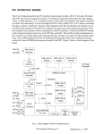
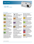
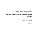
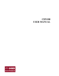
TIMS-1000 SERIES DSP USER MANUAL
Second Edition
Telecommunications Instructional Modeling System
TIMS DSP USER MANUAL
Issue Number 2.0 June 2000
Published by:
Emona Instruments Pty Ltd
86 Parramatta Road
Camperdown NSW 2050
Sydney AUSTRALIA
COPYRIGHT
c
1988,1990, 2000 by EMONA INSTRUMENTS PTY LTD
TIMS is a registered trademark of AMBERLEY HOLDINGS PTY LTD
Printed in Australia
CONTENTS
INTRODUCTION
1
SYSTEM CONVENTIONS
2
TIMS-DSP-RB TMS320C10 PROCESSOR BOARD
Quick Operating Instructions
Detailed Operating Instructions
DSP Program/Hardware Interaction
Specifications
3
4
4
5
8
TIMS-AIB I/O INTERFACE BOARD FOR DSP-RB
Quick Operating Instructions
Detailed Operating Instructions
Analog & Digital I/O
Sampling Clock Generator
Sampling Control
User Interfaces
Specifications
9
10
12
12
13
13
14
15
TIMS-DSP-HS TMS320C50 DEVELOPMENT MODULE
Quick Operating Instructions
Detailed Operating Information
Memory map of the TIMS-DSP-HS
External Program Control and Timing
Creating EPROM Files
Creating Downloadable Files
Programming Hints for the New User
Specifications
16
17
19
19
20
21
22
23
24
TIMS DSP INTRODUCTION
TIMS DSP OVERVIEW
TIMS is a modular telecommunications learning system. It models mathematical equations representing electrical signals, or block diagrams representing telecommunications systems.
The modules of the basic TIMS system, TIMS 301, are very simple electronic circuits which
function as basic communications building blocks, providing signal generation, processing and
measurement functions.
The TIMS-1000 series enhances the basic TIMS system, with TMS320C50 and TMS320C10
based Digital Signal Processing modules. These modules are designed to interface directly to
the traditional electronic modules of the basic TIMS. As well, the TIMS 1000 series DSP modules will emulate the functions of the basic electronic modules or the functions of a series or
system of modules.
The TMS320C50 based module provides an excellent program development environment while
the TMS320C10 based module is ideal for fixed, EPROM-based applications and introduction to
DSP demonstrations. Both modules operate in EPROM mode; the TMS320C50 module will run
programs from EPROM or RAM.
The TMS320C50 module includes all onboard interfaces: analog input and output, digital input
and output, user interfaces and serial link to the PC.
All I/O for the TMS320C10 module is provided by TIMS AIB, Analog Interface Board. The TIMSAIB has high speed, high resolution Analog to Digital Converters, as well as digital inputs and
outputs, and user interfaces. The data and control signals are transferred between the
TMS320C10 and TIMS-AIB modules via the back plane bus.
TIMS-DSP User Manual 1
SYSTEM CONVENTIONS
The TIMS 1000 series modules conform to the same mechanical and electrical conventions as
the basic TIMS 301 system.
A - FRONT PANEL SOCKETS
Signal interconnections are made via front panel, 4mm sockets
Sockets on the LEFT HAND SIDE are for signal INPUTS.
All inputs are high impedance, typically 56k ohms.
Sockets on the RIGHT HAND SIDE are for signal OUTPUTS.
All outputs are low impedance, typically 330 ohms.
YELLOW sockets are only for ANALOG signals.
ANALOG signals are held near the TIMS standard reference level of 4V pk-pk.
RED sockets are only for DIGITAL signals.
DIGITAL signals are TTL level, 0 to 5 V.
GREEN sockets are all common, or system GROUND.
Note that input and output impedances are intentionally mismatched, so that signal connections
may be made or broken without changing signal amplitudes at module outputs.
B - PLUG-IN MODULES
Any plug-in modules may be placed in any of the 12 positions of the upper rack. All modules
use the back plane bus to obtain power supply : only the TIMS-DSP-RB and AIB modules use
the bus to transfer signals. The modules are not locked into position and may need to be held
while interconnecting leads are removed.
C - LABELING
All modules are identified as to the function they perform.
Inputs, outputs, controls and switches are labeled so that a student who has had only a brief introduction to TIMS can use the modules without needlessly referring back to the USER MANUAL.
D - TIMS 320 MODULE LIST
TIMS-DSP-HS TMS320C50-based development module
TIMS-1010-RB TMS320C10-based run board
TIMS-AIB analog interface board for the TIMS-1010-RB only
TIMS-DSP User Manual 2
TIMS-DSP-RB
( TIMS-1010 RUN BOARD )
The TIMS-DSP-RB provides an environment in which DSP programs can easily be tested. Implemented is the T.I. TMS320C10 DSP processor running at 20MHz. Only EPROM configuration is available.
DSP PROCESSOR
RESET
FRONT PANEL
TIMS-DSP User Manual 3
QUICK OPERATING INSTRUCTIONS
The TMS-DSP-RB module may be installed in any position within the TIMS rack. If other DSP
interfacing modules will be used with the processor module, they MUST occupy positions immediately to the RIGHT of the TIMS-DSP-RB.
EPROM Operation: the DSP program is run from a programmed EPROM.
1. SELECT MEMORY CONFIGURATION : ensure the EPROMs are installed correctly.
4kW EPROM mode is set when the MEMORY SELect jumpers are all down ( ’B’ position ). No
other modes are available on the DSP-RB.
2. PROGRAM EXECUTION : press the RESET push button.
DETAILED OPERATING INSTRUCTIONS
EPROM Program Selection
Jumper J1, located near EPROM U5, is used to select which 4kW block of the 8kW EPROM
(2 x 27C64) is available to the TMS320C10 processor. Hence two 4kW programs can be stored
in each EPROM pair. Larger, pin-compatible EPROMs may also be used, e.g. 27C128,
27C256, etc.
When J1 pins 1 and 2 are jumpered (L), the Low block is selected, i.e. $0000 to $0FFF. If J1
pins 2 and 3 (H) are linked, the EPROMs’ upper 4kW is mapped into the DSP processor’s
range.
Memory Configuration
Always ensure the MEMORY SELect switches all DOWN ( ’B’ position )
The EPROMs take up all the available address space from $000 to $FFF. This configuration
suits large fixed programs that only use the TMS320C10’s internal RAM.
TIMS-DSP User Manual 4
DSP PROGRAM AND HARDWARE INTERACTION
After writing and assembling a DSP program, the program’s operation may be verified using a
software simulator. This is particularly useful as the result of each step can be checked under
controlled conditions.
An alternative approach to debugging software, is to observe the sequence of a small number
of key control lines.
The relevant control lines will be identified in this section.
IC identification:
U1 ... TMS320C10, 20MHz DSP processor
U2,U3 ... 74HC368, hex buffers,
U4 ... 74HC27, 3 input NOR, for decoding Input-Output port addressing
U5 ... EPROM 27C64 to 27C256-100ns, High Byte
U6 ... EPROM 27C64 to 27C256-100ns, Low Byte
U7,U8,U9,U10 ... not used. (Option for RAM, 4k x 16 total)
U11
U12
U13
U14
...
...
...
...
74AC00,
74AC08,
74AC11,
74HC74,
2 input NAND, decoding
2 input AND, decoding
3 input AND, decoding
D flip/flop, INTerrupt and BIO synchronization
U15,U16 ... 74AC245, bus transceivers
U17 ... not used
U18 ... SN75155, RS-232 driver
TIMS-DSP User Manual 5
Useful Control Lines
Memory Control Lines
WE .... TMS320 Write Enable. Pin 31; U1. Indicates that valid output data from the TMS320 is
available on the data bus.
DEN .... TMS320 Data Enable. Pin 32; U1. Indicates that TMS320 is accepting data from the input ports.
MEN .... TMS320 Memory Enable. Pin 33; U1. Indicates instruction fetches from program memory.
These memory control lines are active low and mutually exclusive.
Memory Chip Enable Lines
EPROM OE .... Output Enable. Pin 22; U5 and U6.
EPROM CE .... Chip Enable. Pin 20; U5 and U6.
RAM CE .... Chip Enable. Pin 9; U7,U8,U9 and U10.
RAM WE .... Write Enable. Pin 11; U7,U8,U9 and U10.
I/O Control Lines
IOADD .... Input/Output Address Enable. Pin 12; U13. Active high whenever a port is written to
or read from.
MWE .... I/O Write Enable. Pin 8; U12. Data is written to an output port when MWE is low and
IOADD is high.
MDEN .... I/O Data Enable. Pin 6; U12. Data is read from an input port when MDEN is low and
IOADD is high.
DSP Sampling Rate Control Lines
INT .... Interrupt. Pin 5;U1. When a negative going edge is presented to this pin, it causes the
TMS320 to service an interrupt.
BIO .... Branch on Input Low. Pin 9; U1. If a low signal is presented to this pin when the BIOZ
instruction is executed, the TMS320 will branch to the address specified by the instruction.
TIMS-DSP User Manual 6
Getting programs into EPROM
Two data file management programs are provided on the UTILITIES disk:
(i) GENERATING TIMS-ASCII FORMAT FILES
EXTRACT.EXE will extract the op-codes from an assembler LIST (*.LST) file and create a data
file in TIMS-ASCII format. Once a LIST file has been generated by an assembler, type EXTRACT to run the program, and respond to questions as required.
Input: TEXAS TMS32010 assembler LIST (*.LST) file
Output: TIMS-ASCII file with *.OPC extension
(ii) SPLITTING DATA BYTES FOR EPROM PROGRAMMING
ROMEXT.EXE will extract the op-codes from an assembler LIST (*.LST) file and split the data
into HIGH and LOW BYTES, ready for EPROM programming. To run the program type
ROMEXT, and respond to questions as required.
Input: TEXAS TMS32010 assembler LIST (*.LST) file
Output: TWO, (industry standard) ASCII HEX format files, compatible with EPROM
programmers. One file contains the HIGH BYTES, the other contains the LOW
BYTES. User specifies the output file names.
TIMS-DSP User Manual 7
SPECIFICATIONS
DSP processor : Texas Instruments TMS320C10NL
DSP clock rate : 20MHz, crystal
Memory configurations :
MEM1 .. 2k x 16 EPROM, 2k x 16 RAM (not used)
MEM2 .. 4k x 16 EPROM (standard)
MEM3 .. 4k x 16 RAM (not used)
Interface bus : 32 pin, single row, Eurocard format
Pin assignments 1
2
3
4
5
6
7
GND
GND
GND
-15V
-15V
+15V
+15V
8 D0
9 D1
10 D2
11 D3
12 D4
13 D5
14 D6
15 D7
16 D8
17
18
19
20
21
22
23
D9
D10
D11
D12
D13
D14
D15
24
25
26
27
28
29
30
31
32
A0
A1
A2
IOADD
MWE
MDEN
CLK
BIO
INT
TIMS-DSP User Manual 8
TIMS-AIB
( TIMS-1100 ANALOG INTERFACE BOARD )
The TIMS-AIB provides a variety of support facilities for the TIMS-DSP-RB processor board, as
well as access to real-world signals through analog or digital interfaces:
Analog Interfaces : 1 x input, 2 x outputs
Digital Interfaces : 3 x inputs, 3 x outputs, 1 x Interrupt, 1 x BIO
Sample Clock Generator : 1.6usec to 408usec, with 1.6usec resolution.
User Interfaces : 1 x 3 position toggle switch, software readable;
1 x LED, software controllable.
LED DISPLAY
3 POSITION SWITCH
TMS320C10 BIO
TMS320C10 INTERRUPT
TTL INPUTS
TTL OUTPUTS
ANALOG OUTPUTS
ANALOG INPUT
FRONT PANEL
TIMS-DSP User Manual 9
QUICK OPERATING INSTRUCTIONS
Install the TIMS-AIB board immediately to the right of the TIMS- DSP-RB processor board. All
data and control signals will thus be transferred via the back plane bus.
1. SAMPLE CLOCK SELECTION : set J1 for internal or external INTerrupt or BIO. If required internally, INT or BIO use the on-board SAMCLOCK (sample clock). Alternatively, external INT or
BIO signals may be applied via the front panel sockets. J1 pins are labeled as follows:
2. SAMPLE CLOCK SETTING : if an internal sample clock is being used then select the required sample clock rate at SAM CLOCK dip switch. Note that bit 1 is the lsb and bit 8 is msb,
with ON = 1. The switch setting is read in binary, and called the SAMRATE. The resulting
clock rate is:
SAMCLOCK (Hz) = 1/(SAMRATE x 1.6usec)
e.g.. If the required SAMCLOCK is 125kHz, then
SAMRATE = 5 = 0101,
therefore, the switch would be set
NOTE that an INPUT instruction, reading from any input port, MUST be performed after each
triggering of an internal INT or BIO, to reset the SAMCLOCK flip/flop. The SAMCLK frequency
is independent of this resetting action.
3. I/O ADDRESSING : data can only be written to and read from I/O devices using the port address command. Below is the TIMS-AIB port address map.
TIMS-DSP User Manual 10
The analog inputs and outputs only utilize the lower 12 bits.
The digital bits are subdivided as follows:
Data output of the three position toggle switch:
TIMS-DSP User Manual 11
DETAILED OPERATING INSTRUCTIONS
Interfaces
(i) Analog to Digital Converter
Analog to digital conversion is carried out by a single channel 12 bit ADC. The conversion rate
is either 10usec or 3us, depending upon the device installed: AD7572AJN10 is 10usec,
AD7572AJN03 is 3usec. The input is bipolar and has a maximum signal swing of +/-2.5V: this
signal level should not be exceeded. Output code to the ADC is offset binary; i.e. 0000 0000
0000 represents -2.5V and 1111 1111 1111 represents +2.5V. A 3usec sample-and-hold works
in conjunction with the ADC; its operation is transparent to the user.
It is important to note that no anti-aliasing filter is provided at the ADC input. This is so that the
effects of aliasing may be observed directly. If required the TIMS Tunable LPF may be used as
an anti-aliasing filter.
The ADC output is read by the TMS320 using the INPUT command, addressed to port 0.
(ii) Digital to Analog Converter
A dual channel CMOS digital to analog converter is provided. Resolution of each channel is 12
bits; the outputs are bipolar using offset binary coding.
No reconstruction filtering is provided at the DAC outputs, therefore the stepped outputs from
the DACs may be observed directly. If required, the TIMS Tunable LPF may be used for signal
reconstruction.
The DACs can be written to by the TMS320 using the OUTPUT command, addressed to port 0
for DAC 1 and port 1 for DAC 2.
(iii) Digital Inputs
Three digital, TTL level inputs can be read by the TMS320 using the INPUT command, addressed to port 3. Data bits 2 to 4 correspond to DIGITAL INPUTS 1 to 3 respectively.
(iv) Digital Outputs
Three digital, TTL level outputs can be written to by the TMS320 using the OUTPUT command,
addressed to port 3. Data bits 1 to 3 correspond to DIGITAL OUTPUTS 1 to 3 respectively.
TIMS-DSP User Manual 12
Sample Clock Generator
The sample clock, SAMCLK, can be used to provide a regular signal via INTerrupt or BIO, to
which the TMS320 can sample input ports or write to output ports. The SAMCLK is derived
from the TMS320’s own clock, so ADC operations are synchronized with the processor.
An 8 bit dip switch, marked SAMCLK, determines the sampling clock rate, in the following manner:
SAMCLK (Hz) = 1/(SAMRATE x 1.6usec)
where, SAMRATE is a number from 1 to 255, according to the dip switch.
The dip switch should be read RIGHT to LEFT (msb to lsb), where ON = 1 and OFF = 0. All
available 255 clock rates can be calculated from the following chart.
The SAMCLOCK allows the user to fine tune the sampling period, to within 1.6usec of the program’s maximum execution time.
Sampling Control
INTerrupt or BIO are used to provide a regular sampling signal to the TMS320. The sources of
these two signals may be either internal (i.e. on-board) or external. If they are external then the
signals are applied via the TIMS-AIB front panel inputs. If the sources are internal, using the
SAMCLOCK, then jumper J1 is used to direct the SAMCLOCK output to either INTerrupt or
BIO. This SAMCLOCK signal can be observed via the front panel INT and BIO terminals.
TIMS-DSP User Manual 13
IMPORTANT
If the SAMCLOCK is used internally, then a read (i.e. INPUT instruction) from any port MUST
be performed in software after each INT or BIO call. This will reset the SAMCLOCK flip/flop and
enable it to retrigger for the next sampling event.
The SAMCLOCK frequency is completely independent of this resetting action. In most applications, the reason for an interrupt , say, is to read new data from an input port, and thus additional instructions are not required to perform this reset.
User Interfaces
The user interfaces allow interaction between the program and humans.
(i) Input Device
A toggle switch is used either as a three position function selecting switch, or as a variable control - acting like a ’software potentiometer’ - with the center position being ’normal’.
The toggle switches’ contacts can be read by the TMS320 using the input command, addressed
to port 3. Data bits 0 and 1 indicate the switch status as follows,
(ii) Output Device
An LED provides visual output. It can be written to using the output command, addressed to
port 3, data bit 0. When data bit 0 is high, the LED will be lit.
TIMS-DSP User Manual 14
SPECIFICATIONS
Analog Interfaces :
Input - AD7572 single channel, 12bit, CMOS, successive approximation;
conversion rate AD7572AJN10, 10usec; AD7572AJN03, 3usec;
sample-and-hold time, 3usec;
Bipolar output, +/-2.5V; offset binary.
Output - AD7547JN dual channel, 12 bit, CMOS;
Bipolar output, +/-2.5V; offset binary.
Digital Interfaces :
Input - 3 x TTL level.
Output - 3 x TTL level.
Special - 1 x INTerrupt, TTL level, input/output;
1 x BIO, TTL level, input/output.
Sample Clock Generator :
1.6usec to 408usec, with 1.6usec resolution.
User Interfaces :
Input - 3 position toggle switch;
Output - single LED.
TIMS-DSP User Manual 15
TIMS-DSP-HS
( TIMS-1050 DSP DEVELOPMENT MODULE )
The TIMS-DSP-HS provides a DSP program development environment for the TMS320C50
processor. The module includes a variety of analog, digital and user inputs and outputs.
DSP programs may be entered by either inserting preprogrammed EPROMs, or by downloading the program into RAM via the serial RS-232 interface. The DSP processor also takes care
of the serial communications with the host computer, as well as basic monitor functions.
3 POSITION SWITCH
ON THE LEFT
RS-232 PC INTERFACE
RED LED ON THE RIGHT
RED DIGITAL
INPUTS 1, 2 & 3
ON THE LEFT
HARDWARE RESET
TO THE DSP PROCESSOR
RED DIGITAL
OUTPUTS 1, 2 & 3
ON THE RIGHT
YELLOW ANALOG
INPUTS ADC 1, 2 & 3
ON THE LEFT
RED "XBIO" INPUT
RED INTERRUPT INPUT
YELLOW ANALOG
OUTPUTS DAC 1, 2 & 3
ON THE RIGHT
FRONT PANEL
TIMS-DSP-HS utilizes the TMS320C50, industry standard fixed point DSP, with 50ns instruction
cycle time with 32k word program memory and 32k word data memory. The TIMS-DSP-HS
module includes three TIMS-level analog inputs and outputs, three TTL-level digital inputs and
outputs, a three position user readable switch and a programmable LED.
Note: the similarity between the labeling of the TIMS-AIB module’s inputs and outputs and the
TIMS-DSP-HS module’s inputs and outputs. Application programs supplied by Emona for the
TIMS-DSP-RB/TIMS-AIB and the TIMS-DSP-HS, such as the CONVOLUTIONAL and TCM DECODER, are written to use inputs and outputs with the same labels. For example, if OUT1 is
programmed to provide a TCM bit clock on the TIMS-AIB module, then the TIMS-DSP-HS module’s OUT1 will also provide a bit clock when running the matching TCM application program on
the TIMS-DSP-HS.
The TIMS-DSP-HS utilizes and enhances the capabilities of the Texas Instruments
TMS320C5x DSK. The DSK is a daughter board to the TIMS-DSP-HS and provides an easy to
use debugger environment for communicating with a PC via the front panel serial interface. Do
not connect any signals to the DSK board’s RCA or 9-pin D connectors. ALL DSK SIGNALS
ARE AVAILABLE AT THE FRONT PANEL OF THE TIMS-DSP-HS MODULE.
Note: The T.I. TMS320C5x DSK is supplied fully installed and tested on the TIMS-DSP-HS. All
original manuals and disks supplied by T.I. with the DSK are included with the TIMS-DSP-HS
package.
TIMS-DSP User Manual 16
QUICK OPERATING INSTRUCTIONS
The TIMS-DSP-HS module may be installed in any position within the TIMS rack.
A - EPROM Operation
DSP program is run from a programmed EPROM.
1. SELECT EPROM OPERATING MODE: locate jumper J2. It is at the rear of the large circuit
board, near L3 and U22. Position the jumper in the EXT position (top two pins shorted). Jumper
J2 allows two operating modes to be selected: EXTernal (run program from EXTernal EPROM)
and INTernal (run program in RAM and use INTernal Debugger Monitor).
Locate jumper J3. It is near the front of the large circuit board. Ensure the jumper is set in the
LO position. (This is a user readable jumper which can be used, for example, to select which
application to run when the EPROM or RAM has had two applications programmed at different
address locations.)
2. INSTALL EPROM: install a preprogrammed EPROM, e.g. the LPF10.HS low pass filter program, into socket U24 on the large circuit board. Take care to ensure the correct orientation.
(The EPROM’s pin 1 should be near the label U24).
3. PROGRAM EXECUTION: plug the TIMS-DSP-HS into any position within the TIMS rack.
Press the front panel RESET push button. Connect and view the signals as appropriate. For example, if running the LPF10.HS program, patch the AUDIO OSCILLATOR sine output to ADC 1
and view the outputs signals as DAC 1 and DAC 2.
B - Download Operation
DSP program code is downloaded from a host computer into RAM.
1. SELECT RAM OPERATING MODE: locate jumper J2. It is at the rear of the large circuit
board, near L3 and U22. Position the jumper in the INT position (lower two pins shorted).
Jumper J2 allows two operating modes to be selected: EXTernal (run program from EXTernal
EPROM) and INTernal (run program in RAM and use INTernal Debugger Monitor).
Locate jumper J3. It is near the front of the large circuit board. Ensure the jumper is set in the
LO position. (This is a user readable jumper, which can be used, for example, to select which
application to run when the EPROM or RAM has had two applications programmed at different
address locations.)
2. CONNECT SERIAL LINK: plug the TIMS-DSP-HS into any position within the TIMS rack.
Plug one end of the serial cable to the SERIAL LINK front panel connector and the other end
into the host computer’s serial communications port.
3. RUN THE MONITOR PROGRAM: run the latest version of the T.I. debug monitor program. A
copy (for example, file name DSK5d103.exe for version 1.03) is located on the original T.I.
floppy disk supplied with the original DSK manuals box.
TIMS-DSP User Manual 17
As soon as the monitor establishes communications with the TIMS-DSP-HS, the Debugger
Monitor windows will open showing processor information. If communication is not established,
then follow the on-screen instructions for port and baud rate setting, using the keyboard arrow
keys.
4. PROGRAM DOWNLOAD:
(i) type L for load, to select program download;
(ii) type C for COFF (Common Object File Format) file format, which has an "*.out" extension;
(iii) type the filename, e.g. lpf10c.out;
(iv) type N to select download and verify;
(v) when download is completed, hit the SPACE BAR key to return to the monitor main menu.
5. PROGRAM EXECUTION:
(i) type X to select the execute menu;
(ii) type G for go, to start the program running.
Connect and view the signals as appropriate. For example, if running the lpf10.out low pass filter program, patch the AUDIO OSCILLATOR sine output to ADC 1 and view the outputs signals as DAC 1 and DAC 2.
Note: to reset the processor, use the Debugger’s keyboard commands: do not use the front
panel RESET push button. The front panel RESET push button is only used in EPROM mode.
TIMS-DSP User Manual 18
DETAILED OPERATING INFORMATION
Programs can be executed by downloading from a PC to the onboard Program memory RAM
and run via the Debugger interface window. Stand-alone operation, without connection to a PC,
is also possible by running the program out of a user programmed and installed EPROM.
EPROM mode is useful for running programs once they have been developed and completed.
The two operating modes are selected via a single jumper, J2, with two positions being INTernal (run the program in RAM and use the INTernal Debugger Monitor) or EXTernal (run the program EXTernal EPROM).
Use of the debugger is discussed in detail in the TMS320C5x DSP Starter Kit Users Guide
which is supplied. Creation of the EPROM is discussed later in this manual.
Memory map of the TIMS-DSP-HS
The 320C50 has 9K of full speed internal memory which can be configured to be either program memory or data memory. (Refer to Chapter 8 of Users Guide).
In addition to this the TIMS-DSP-HS provides the following:
32K-word PROGRAM memory space in RAM from 8000h to FFFFh, and
32K-word DATA memory space in RAM from 8000h to FFFFh.
The following TIMS-DSP-HS module I/O devices are mapped into the TMS320C50’s I/O space
and data space, and are addressable as listed below.
NOTE: There is a ’hole’ in data space at addresses 0050h to 0053h, which allows these I/O devices to be addressed with data manipulation instructions and to be observable with the debugger. The debugger does not support I/O space.
INPUTS 0050h: ADC 1 (12 bit, 10us conversion time)
0051h: not used
0052h: not used
0053h: DIGITAL IN 1, 2, 3, USER Switch, XBIO and J3.
0053h bit:
INPUT:
7
J3
6
-
5
* BIO
(XBIO)
4
INPUT
3
3
INPUT
2
2
INPUT
1
1
SW
0
SW
It is important to note that no anti-aliasing filter is provided at the ADC 1 input. This is so that
the effects of aliasing may be observed directly. If required the TIMS Tuneable LPF may be
used as an anti-aliasing filter.
* Please refer to the description of how BIO is implemented on the following page.
OUTPUTS 0050h: DAC 1 (12 bit)
0051h: DAC 2 (12 bit)
0052h: not used
0053h: DIGITAL OUT 1, 2, 3 and LED
TIMS-DSP User Manual 19
0053h bit:
OUTPUT:
7
-
6
-
5
-
4
-
3
OUTPUT
3
2
OUTPUT
2
1
OUTPUT
1
0
LED
No reconstruction filtering is provided at the DAC 1 & DAC 2 outputs, therefore the stepped outputs from the DACs may be observed directly. If required, the TIMS Tuneable LPF may be
used for signal reconstruction.
ADC 2, ADC 3 and DAC 3 are supported by the onboard TLC32040 AIC (analog interface circuit) device and are controlled via the programming of specified control registers. They are all
14 bit converters, with a maximum sample rate of 19,200 samples per second. ADC 2 & ADC 3
include switched capacitor antialiasing filters and DAC 3 includes a switched capacitor reconstruction filter. The original AIC data sheet is provided with the other DSK Starter Kit manuals.
External Program Control and Timing
Two common ways of controlling program timing externally are via the BIO and INT functions of
the TMS320C50.
INT
The front panel INT terminal connects, via buffering, to INT1 (Interrupt 1) of the processor.
BIO (XBIO)
The processor’s true BIO pin is not available to the user as it is used by the DSK debugger.
This means that BIO based instructions cannot be used.
As BIO is a level sensitive input, the TIMS-DSP-HS provides an alternative BIO input for the
user, known as "XBIO". The front panel terminal labeled BIO actually connects to bit 5 of input
address 0053h and can be polled to provide a level sensitive input (in the same way as digital
inputs IN 1, 2, 3). This front panel BIO is actually the TIMS-DSP-HS module’s "XBIO".
BIO to INT2
If a second external interrupt is required, it is possible to connect the front panel terminal labeled BIO to the processor’s INT2 pin. This is done by jumping positions A and B on the
header J1, on the large circuit board.
NOTE: do not jumper any other combination of pins A, B C or D, as this may disrupt the TIMSDSP-HS module’s operation.
J3 on the large PCB
Jumper J3 is a user readable jumper which is connected to data bit 7 of input address 0053h. It
has 2 settings: HI and LO which correspond to the TTL signal level of that pin. This jumper is
useful as another user setting for program control. As it is not on the front panel, it will not be
accidentally modified during front panel operation.
J3 can be used, for example, to select which application to run when the EPROM or RAM has
two applications programmed at different address locations.
Software Timer Interrupts
The internal Timer is available to generate periodic CPU interrupts.
This function is in addition to the normal functions of the DSK daughter board. (Refer to Section
9.3, page 9-9 of User Guide for details.)
TIMS-DSP User Manual 20
CREATING EPROM FILES
The following lists the procedure on how to create an EPROM for running programs on the
TIMS-DSP-HS.
The TMS320C50 has a Boot Loader mode which, upon reset, will load a program from an external EPROM into its internal memory space and then execute that program.
This Boot Loader mode is discussed in detail in the TMS320C5x User Guide - see Section 8.8,
page 8-32. The mode which is used for the TIMS-DSP-HS is the 8-bit parallel EPROM mode see Section 8.8.3
The EPROM is programmed from an Intel Hex file (filename.i0) which is created by the Hex
Conversion Utility program (dsphex.exe) provided with the Texas Instruments COFF Assembly
Language Tools, from a COFF object file. Its use is discussed in the TMS320C5x Assembly
Language Tools Users Guide - see Section 11, page 11.1
The COFF (Common Object File Format) object file is an industry standard file format, created
by a COFF assembler and linker, which is also provided within the above mentioned tools.
Steps to create a boot EPROM for the TIMS-DSP-HS :
Creating a boot EPROM allows you to run your program from an EPROM installed in the TIMSDSP-HS, without the use of a PC.
1) Take an executable COFF file, e.g. lpf10c.out, and create a Boot Loader Command file,
e.g. lpfboot.cmd . This file selects an Intel Hex format.
2) Open an MS-DOS prompt window and run the application dsphex lpfboot to create lpf10c.i0,
an Intel Hex file. This Intel Hex file can be programmed into a 32k EPROM and plugged into
the TIMS-DSP-HS module. (Larger pin compatible EPROMs may also be used.)
Once the Intel Hex file is loaded into the EPROM programmer, manually set the last location
(7fffh) to 81h. This location is read by the TMS320C50 processor upon reset to determine
which boot loader mode to use. See Section 8.8 of TMS320C5x Users Guide for details.
3) Insert the programmed EPROM into the 28 pin socket labeled U24 and set jumper J2 to EXT.
4) Upon RESET the processor will load the application program from this EPROM into its internal program memory and execute.
TIMS-DSP User Manual 21
CREATING DOWNLOADABLE FILES FOR RAM OPERATION
The following lists how to use the COFF Assembler to create files that can be downloaded and
run in the TIMS-DSP-HS module’s RAM.
1) Create a file using the protocol outlined in the TMS320C5x Assembly Language Tools:User
Guide. This Guide is provided with the COFF Assembler. For example the low pass filter program, lpf10c.asm, as well as its Linker Command file, lpf10c.cmd
2) Open the MS-DOS Prompt window and invoke the COFF Assembler as follows:
dspa lpf10c -l -v50 -x
This will create an Object File, e.g. lpf10c.obj, and a List File, e.g. lpf10c.lst
3) Within an MS-DOS Prompt window, invoke the Linker as follows:
dsplnk lpf10c.cmd
This will create an executable COFF file and a Map file.
4) Run the DSK debugger, dsk5d103.exe, and load the "*.out" file as follows:
From the menu select: Load, Coff, and enter the filename, e.g. lpf10c.out;
When loading is complete, to run select: eXecute, Go
The debugger will run the loaded program from its start address, e.g. 0a00h. The program operation can now be observed via the front panel of the TIMS-DSP-HS module.
Refer to the COFF assembler User Guide for further options.
The DSK menu is explained in detail in the TMS320C5x DSP Starter Kit.
NOTE: the T.I. COFF Assembler is available separately from Texas Instruments and is not included as standard with the TIMS-DSP-HS module.
TIMS-DSP User Manual 22
PROGRAMMING HINTS FOR THE NEW USER
- When using internal RAM make sure that the PMST register enables the SARAM to either
data or program space with no conflict and as you have intended.
- Remember to set the DP pointer to the correct location for your variables. It is easy to forget
to set the DP correctly.
- When running programs from the debugger, beware that flags etc are not initialized to the
hardware reset value in the data book but are set to values used by the debugger. To avoid errors it is good practice to initialize all relevant flags from within your program.
- Beware of the peculiar syntax of the BIT instructions. When referring to a particular bit you
must enter the ’bit code’ into the instruction rather than the bit number e.g. to test the lsb (bit 0)
of location 53h, the instruction is BIT 0053h,0Fh. This is easily overlooked.
- Remember that the AIC inputs (ADC 2 & 3) and output (DAC 3) operate with 2’s complement
notation whereas ADC 1 and DAC 1 and DAC 2 use offset binary notation (where -2V=0000h
and +2V=FFFFh).
- BEWARE OF PIPELINE CONFLICTS !!!
YOU MUST READ CHAPTER 7, ESPECIALLY SECTIONS 7.2. & 7.2.3 if using ARs.
You need to take care after SAMM and LAMM instructions. A simple, though heavy-handed solution is to put 2 NOPs after each SAMM or LAMM. A pipeline conflict will give unexpected values showing up in your registers.
- TMS325C50 Application Files
Visit the Texas Instruments DSP web site to view a large range of application programs written
for the DSK.
TIMS-DSP User Manual 23
SPECIFICATIONS
DSP processor: Texas Instruments TMS320C50
DSP instruction cycle: 50ns
Memory configurations:
RAM: 64kW, with 32kW Program space and 32kW Data space;
EPROM: 32kW space, 28 pin socket.
Communications Port: RS-232, 4 lines.
Analog Interfaces:
INPUT 1 - AD7572 single channel, 12bit, CMOS, successive approximation;
conversion rate AD7572AJN10, 10usec; AD7572AJN03, 3usec;
Bipolar input, +/-2.5V; offset binary output;
no antialiasing filter provided.
INPUT 2 & 3 - TLC32040 AIC, 14bit, CMOS,
conversion rate 19,200 samples per second,
Bipolar input, 2’s compliment output;
Switched capacitor antialiasing input filters provided.
OUTPUT 1 & 2 - AD7547JN dual channel, 12 bit, CMOS;
Bipolar output, +/-2.5V; offset binary;
no reconstruction filters provided.
OUTPUT 3 - TLC32040 AIC, 14bit, CMOS,
Bipolar output, 2’s compliment input;
Switched capacitor reconstruction output filter provided.
Digital Interfaces :
INPUT 1, 2 & 3 - 3 x TTL level;
OUTPUT 1, 2 & 3 - 3 x TTL level;
INT - 1 x interrupt to processor’s INT1, TTL level;
BIO - 1 x "XBIO", TTL level; with access to processor’s INT2;
Sample Clock Generator :
Internal, software programmable.
User Interfaces :
Input - 3 position toggle switch;
Output - single LED.
TIMS-DSP User Manual 24