1
Doc No. 1723-PS-0017
Issue 1
User Manual
MetPak Pro Base Station
MetPak Pro Base Station Part: 1723-2A-X-XXX
Foreword
© 2011 Gill Instruments Ltd. All rights reserved.
Thank you for purchasing the MetPak Pro Base Station manufactured by Gill
Instruments Ltd. To achieve optimum performance we recommend that you read
the whole of this manual before proceeding with use.
Gill products are in continuous development and therefore specifications may be
subject to change and design improvements without prior notice.
The information contained in this manual remains the property of Gill Instruments
and should not be copied or reproduced for commercial gain.
Guarantee
For terms of guarantee, please contact your supplier.
Trademarks
Microsoft and Windows are registered trademarks of Microsoft Corporation.
All other brands and product names are trademarks or registered trademarks of
their respective owners.
Cautions and Notes
The following symbols are used in this guide:
CAUTION. This indicates an important operating instruction that should be
followed to avoid any potential damage to hardware or property, loss of data,
or personal injury.
NOTE. This indicates important information to help you make the best use of this
product.
Applicable Parts
MetPak Pro Base Station 1723-2A-1-111 (Base Station only).
MetPak Pro Base Station 1723-2A-2-111 (with White WindSonic Option 2).
MetPak Pro Base Station 1723-2A-3-211 (with Heated WindSonic M).
MetPak Pro Base Station 1723-2A-4-311 (with Heated WindObserver).
MetPak Pro Base Station 1723-2A-5-111 (with WindMaster).
MetPak Pro Base Station 1723-2A-6-111 (with WindMaster Pro).
Contents
1.
Introduction ......................................................................................................... 1
1.1
Principle of Operation...................................................................................................... 2
1.1.1
Wind Speed and Direction Sensor ..................................................................... 2
1.1.2
Radiation Shield ................................................................................................ 3
1.1.3
Temperature and Relative Humidity Sensor with Dewpoint Output .................... 3
1.1.4
Barometric Pressure.......................................................................................... 3
1.1.5
Sensor Inputs .................................................................................................... 3
1.2
Abbreviations .................................................................................................................. 4
2.
Installation ........................................................................................................... 5
2.1
Pre-Installation Checks ................................................................................................... 5
2.1.1
Spare Parts ....................................................................................................... 5
2.2
Installation....................................................................................................................... 6
2.2.1
Bench system test ............................................................................................. 6
2.2.2
Bench Test Equipment Required ....................................................................... 6
2.2.3
Cabling .............................................................................................................. 7
2.2.4
Communication and Power Connections ......................................................... 14
2.2.5
Analogue, Digital and PRT Input Connections ................................................. 18
2.2.6
MetPak Pro Base Station System Connections ............................................... 21
2.2.7
Mounting MetPak Pro Base Station ................................................................. 27
2.2.8
Mounting MetPak Pro Base Station Junction Box ............................................ 29
2.2.9
Mounting MetPak Pro Base Station Heater Power Interface Box..................... 31
3.
Operation ........................................................................................................... 33
3.1
Start Guide.................................................................................................................... 33
3.2
MetView ........................................................................................................................ 35
3.2.1
Opening MetView ............................................................................................ 35
3.2.2
Scanning for Devices....................................................................................... 36
3.2.3
The MetView Console ..................................................................................... 37
3.2.4
MetView Console Display Options ................................................................... 39
3.2.5
MetView Gauge Ranges and Graphs .............................................................. 40
3.2.6
Data logging .................................................................................................... 42
3.3
MetPak Pro Base Station Configuration ........................................................................ 45
3.4
Configuring MetPak Pro Base Station with MetSet........................................................ 47
3.4.1
Opening MetSet .............................................................................................. 47
3.4.2
MetSet Editing Screen ..................................................................................... 49
3.4.3
Monitoring MetPak Pro Base Station Output Data Using HyperTerminal. ........ 56
3.4.4
Configuring MetPak Pro Base Station for SDI-12 ............................................ 58
Last Change
22 April, 2013
MetPak Pro Base Station User Manual
© Gill Instruments Ltd
Page i
Contents
3.4.5
3.4.6
4.
SDI-12 Commands .......................................................................................... 58
Safe Mode ....................................................................................................... 63
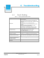
Troubleshooting ................................................................................................ 65
4.1
Fault-Finding ................................................................................................................. 65
4.2
Servicing ....................................................................................................................... 67
4.3
Bench Tests .................................................................................................................. 67
5.
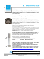
Maintenance ...................................................................................................... 69
6.
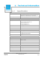
Technical Information .......................................................................................... i
6.1
Specification .................................................................................................................... i
6.2
MetPak Pro Base Station Hub PCB Connections ............................................................ iv
6.3
Electrical Conformity Certificate ...................................................................................... vi
Figures
Figure 1 U and V Compass points 2 Axis Instruments
Figure 2 Position of Temperature and Relative Humidity Probe in the Radiation Shield
Figure 3 Internal view of the hub box (top circuit board removed).
Figure 4 Hub Box with Analogue and Digital Pec fitted.
Figure 5 Connection of Gill USB Cable (Part No. 1723-10-051)
Figure 6 RS232 connections
Figure 7 RS422 connections
Figure 8 RS485 Connections
Figure 9 SDI-12 connections
Figure 10 MetPak Pro Base Station Example System Picture
Figure 11 Mounting and Dimensions for MetPak Pro Base Station
Figure 12 Opening MetView Screen
Figure 13 Scanning for MetPak Pro Base Station Devices
Figure 14 The MetView Console
Figure 15 MetView Gauge Range
Figure 16 MetView Graph
Figure 17 Setting up data logging
Figure 18 Opening MetSet Screen
2
3
14
15
15
16
16
17
17
22
28
35
36
37
40
41
42
47
Tables
Table 1
Table 2
Table 3
Table 4
Table 5
Table 6
Table 7
Table 8
Table 9
Table 10
Abbreviations
Recommended Belden cable types
Maximum cable lengths for supported communication and sensor network
Connection status indicators
MetView scale and unit options
MetView averaging options
Max/min markers
MetView Screen Settings Options
Default configuration settings
MetPak Pro Base Station Commands
MetPak Pro Base Station User Manual
© Gill Instruments Ltd
Page ii
4
12
13
37
39
39
39
39
45
57
Last Change
22 April, 2013
Table 11
Table 12
Table 13
Table 14
Table 15
Table 16
Table 17
Table 18
Common problems and their solution
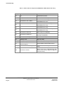
Status codes as output with the MetPak Pro Base Station data string
HygroClip connections (6-way connector J1)
Wind Sensor 10 Metre Cable connections (8-way connector J4)
PC communications (8-way connector, J5)
PRT Sensor (4-way connector, J7)
Digital Switch Input (2-way connector, J8)
Analogue Sensors Input (8-way connector, J9)
MetPak Pro Base Station User Manual
© Gill Instruments Ltd
Page iii
65
66
iv
iv
v
v
v
v
Last Change
22 April, 2013
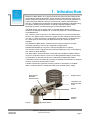
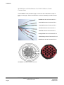
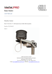
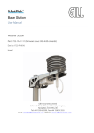
1. Introduction
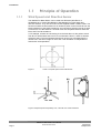
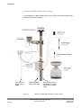
MetPak Pro Base Station is a compact multi-sensor instrument that measures the
most essential weather parameters. It also provides a data collection system that
allows customers to add their own selection of sensors to meet local requirements.
A Gill Instruments Ultrasonic Sensor can be used to measure wind speed and
direction. Temperature and Humidity are measured and Dewpoint calculated using
an industry standard probe housed in a naturally aspirated radiation shield.
Barometric pressure is measured using an industry standard sensor.
The Wind Sensor can be chosen from a 2 axis WindSonic Option 2 (white),
WindSonic M Heated, WindObserver 70 enhanced heated or a 3 axis WindMaster
or WindMaster Pro.
The customer is able to add up to four additional sensors. One PRT (temperature
sensor), one digital (contact closure rain gauge) and two analogue inputs (4-20mA
or 0-5V) e.g. water level sensor, pyranometer, pressure sensor, soil temperature
etc. Other types of sensors may be added limited by the number of inputs
available.
The MetPak Pro Base Station combines all the instrument data into a single
combined data string. This may be configured for digital ASCII
RS232/RS422/RS485 (2 wire point to point) and digital SDI-12 outputs.
The instrument uses a rugged mounting clamp that attaches to any vertical pipe up
from 30mm to 58mm diameter.
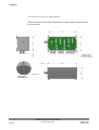
The Base Station electrical Hub box comes with a pre-installed 10 Metre cable to
connect to a Gill Wind Sensor. There is one cable gland allocated to provide entry
for termination of other sensors and one cable gland for data/power cables.
A separate Junction box (optional accessory) is available for termination of external
sensors, power and communication cables.
A Heater Interface box (optional accessory) allows for termination of the Base
Station 10 Metre cable to a heated Wind Sensor and Heater power supply.
Gortex Vent for
Barometric
Pressure Sensor
Radiation shield
Temperature and
Relative humidity
sensor
Hub box
Mounting
bracket
Figure 1
Last Change
22 April, 2013
MetPak Pro Base Station
MetPak Pro Base Station User Manual
© Gill Instruments Ltd
Page 1
Introduction
1.1
1.1.1
Principle of Operation
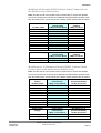
Wind Speed and Direction Sensor
The MetPak Pro Base Station can be used with Gill 2axis (WindSonic or
WindObserver) or 3 axis (WindMaster or WindMaster Pro) wind speed and
direction sensors. They are connected via the supplied RS422 10 Metre cable. The
sensors measure the times taken for an ultrasonic pulse of sound to travel from the
North transducer to the South transducer, and compares it with the time for a pulse
to travel from S to N transducer. Likewise times are compared between West and
East, and E and W transducer.
If, for example, a North wind is blowing, then the time taken for the pulse to travel
from N to S will be faster than from S to N, whereas the W to E, and E to W times
will be the same. The wind speed and direction can then be calculated from the
differences in the times of flight on each axis. This calculation is independent of
factors such as temperature.
Figure 1
U and V Compass points 2 Axis Instruments
Figure 2 Compass points and polarity of U, V and W on a 3 axis instrument.
MetPak Pro Base Station User Manual
© Gill Instruments Ltd
Page 2
Last Change
22 April, 2013
Introduction
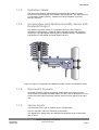
1.1.2
Radiation Shield
The Multi-Plate Radiation Shield protects temperature and relative humidity
sensors from error-producing solar radiation and precipitation. This shield relies on
a combination of plate geometry, material and natural ventilation to provide
effective shielding.
1.1.3
Temperature and Relative Humidity Sensor with
Dewpoint Output
The Rotronic HygroClip module is a complete instrument, with integrated
temperature compensation. Calibration data is maintained within the integrated
electronics. It provides digital output signals for Relative Humidity, Temperature
and Dewpoint to the MetPak Pro Base Station Hub box.
Figure 2 Position of Temperature and Relative Humidity Probe in the Radiation Shield
1.1.4
Barometric Pressure
Barometric pressure output is provided by a solid-state device fitted on to the
circuit board in the MetPak Pro Base Station Hub box. Vent to atmosphere is via a
Gortex filter which also protects the pressure sensor from the effects of wind and
rain.
1.1.5
Sensor Inputs
Two analogue inputs, 0-5V or 4-20mA (loop or self-powered).
One four wire PRT 100 input conforming to IEC 60751.
One Digital input, detects when two dedicated terminals are short circuited (less
than 1k ohm).
Last Change
22 April, 2013
MetPak Pro Base Station User Manual
© Gill Instruments Ltd
Page 3
Introduction
1.2
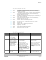
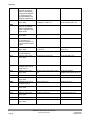
Abbreviations
Table 1
Item
ASCII
C
CAL
CD
COM
CR
CSV
ETX
F
FPM
HF
HPA
HTML
Hz
IMM
In Hg
K
KPH
KTS
LF
M Bar
Max
MF
Min
Mm Hg
MPH
MS
MS
NSEW
NVM
PC
ROM
RS232
RS422
Rx
RXD
SDI-12
STX
Tx
TXD
VHF
WMO
Abbreviations
Meaning
American Standard Code for Information Interchange
Centigrade
Calibration
Compact Disc
Communications
Carriage Return
Comma Separated Variable
End of String
Fahrenheit
Feet per Minute
High Frequency
Hecto-Pascals
Hyper Text Markup Language
Hertz
International Maritime Mobile
Inches of Mercury
Kelvin
Kilometres per Hour
Knots
Line Feed
Milli Bars
Maximum
Medium Frequency
Minimum
Millimetres of Mercury
Miles per Hour
Microsoft
Metres per Second
North South East West
Non-Volatile Memory
IBM compatible Personal Computer
Read Only Memory
Communications standard
Communications standard
Receive
Received Data
Serial – Data Interface standard for microprocessor based
sensors
Start of String
Transmit
Transmitted Data
Very High Frequency
World Meteorological Organisation
MetPak Pro Base Station User Manual
© Gill Instruments Ltd
Page 4
Last Change
22 April, 2013
2. Installation
MetPak Pro Base Station has been designed to meet and exceed the stringent
standards listed in its specification (see Para 6.1).
2.1 Pre-Installation Checks
As with any sophisticated electronics, good engineering practice should be followed to
ensure correct operation:
Ensure the MetPak Pro Base Station and Wind Sensor will not be affected by other
equipment operating locally, which may not conform to current standards, e.g.
radio/radar transmitters, generators etc.
Avoid mounting in the plane of any radar scanner – a vertical separation of at least
2m should be achieved.
When installing MetPak Pro Base Station and Wind Sensor near radio transmitting
antennas, ensure that the mounting position fulfills the following minimum
separations (all round):
VHF IMM – 1m
MF/HF – 5m
Satcom – 5m (avoid likely lines of sight)
Use cables recommended by Gill (see Para 2.2.3). If cables are cut and reconnected incorrectly (perhaps in a junction box) then EMC performance may be
compromised if cable screen integrity is not maintained.
Avoid earth loops – wire the system in accordance with these installation
guidelines.
Ensure that the power supply operates to the MetPak Pro Base Station and Wind
Sensor specification (see Para 6.1) at all times.
Avoid turbulence caused by surrounding structures that will affect the accuracy of
the sensors such as trees, masts and buildings. The WMO make the following
recommendations. The standard exposure of wind instruments over level open
terrain is 10m above the ground. Open terrain is defined as an area where the
distance between the sensor and any obstruction is at least 10 times the height of
the obstruction.
Keep away from building exhaust vents, machinery and motors.
2.1.1
Last Change
22 April, 2013
Spare Parts
1723-PK-201
Junction Box with internal terminating pcb.
1723-PK-202
Terminating pcb (to mount in customer box).
1723-PK-204
Pack of 4 feet for Panel Mounting the Junction Box.
1723-PK-203
Pack of 4 brackets for Pole Mounting the Junction Box.
1723-10-051
RS232 to USB 1.8M configuration cable (excluding WindObserver
and WindMaster/Pro connected units).
1723-PK-024
Pressure Sensor Filter Spares kit.
1723-PK-025
Hygroclip Filter Replacement Kit (2 Filters).
1723-PK-099
Heater Power Interface Box.
MetPak Pro Base Station User Manual
© Gill Instruments Ltd
Page 5
Installation
2.2
2.2.1
Installation
Bench system test
Prior to physically mounting the MetPak Pro Base Station in its final location, we
strongly recommend that a bench system test is carried out to confirm the system
is configured correctly, is fully functional and electrically compatible with the
selected host system and cabling (preferably utilising the final cable length). The
required data format, units, output rate, and other options should also all be set up
at this stage.
2.2.2
Bench Test Equipment Required
1723-2A-X-XXX/X MetPak Pro Base Station set for RS232 communication (factory
default setting).
1723-10-051
MetPak Pro Base Station RS232 to USB 1.8M configuration cable
with integral 5v power (for WindSonic units only). Otherwise use
RS232 I/F converter and separate 12v to 30 dc power supply.
ES-U-1001-A
EasySynch RS232 to USB adaptor or equivalent (if not using Gill
part 1723-10-051) or connect directly to an RS232 COM port.
Power Supply 12Vdc to 30Vdc at 100mA if required.
Belden 9503 3 pair communications and power cable (if not using Gill Part 172310-051), length as required.
Belden cable with up to 6 pairs for Analogue, Digital and PRT inputs.
Gill MetSet Software supplied on the MetPak Pro Base Station CD or download
from. http://www.gill.co.uk/main/software.html
Wind Sensor- should be configured as per the following list:1405-PK-072
WindSonic Option 2 White
M4,U1,O1,L1,P1,B4,H2,NQ,F1,E2,T1,S4,C2,G0,K0,
1405-PK-200
WindSonic M Heated
M4,U1,O1,L1,P1,B4,H2,NQ,F1,E2,T1,S4,C2,G0,K0,
1390-70-B-312 WindObserver 70 heated with short connector base.
Note - Firmware Version V 6.02 onwards
M4,U1,O1,L1,P1,B4,H2,NQ,F1,E2,T1,S4,C2,G0,K0,
1590-PK-020
WindMaster
M4,U1,O1,L1,P1,B4,H2,NQ,E1,T1,S1,C2,A4,I1,J1,V1,X1,G0,K0,F1 1,F2 0,F3 1
1561-PK-020
WindMaster Pro
M4,U1,O1,L1,P1,B4,H2,NQ,E1,T1,S1,C2,A4,I1,J1,V1,X1,G0,K0,F1 1,F2 0,F3 1
For Power Supply/Supplies and cables suitable for the chosen Wind sensor see
relevant wind sensor manual supplied with the sensor or download from
http://www.gill.co.uk/data/manuals/manuals.htm .
MetPak Pro Base Station User Manual
© Gill Instruments Ltd
Page 6
Last Change
22 April, 2013
Installation
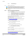
2.2.3
Cabling
Base Station RS422 10 Metre Cabling
The MetPak Pro Base Station comes with an integral 10 Metre, Belden 8104 cable
fitted to the hub box connector J4, (RS422 interface).
It is terminated in Clipper connector solder contacts for installing into a WindSonic
Option 2 or WindMaster/WindMaster Pro Connector (connectors supplied with the
Wind Sensor).
If used with a WindObserver 70 or WindSonic M the contact pins will need to
be cut off and wire stripped/soldered for termination into the Heater Power
Interface Box.
Details on fitting the connector pins on the 10 Metre cable into the WindSonic
option 2 or WindMaster/WindMaster Pro connector are as follows:If shortening the 10 Metre cable to a required length, strip and prepare as follows:1. Trim back the screened cable outer PVC sheath to 52mm.
2. Trim back the braid and drain wire to 20mm from the outer sheath.
3. Separate braid and drain wire from the foil and cores. Twist braid and drain
wires together.
4. Trim the twisted braid and drain wire to 15mm from the outer sheath and
tin ends 5mm.
5. Cut the foil and White/Green wire back to within 5mm of the outer sheath.
6. Strip and tin one end of the White/Green wire removed to 5mm.
7. Locate White/Green wire to twisted braid and drain wire and solder.
8. Insulate the White/Green wire joint.
9. Strip back the connection wires by 4mm and tin solder.
10. Solder the contact pins supplied with the connector to the wires.
11. Note that the sensor connector supplies the correct strain relief for cables
with an outside diameter of 6-12mm.
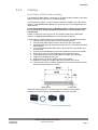
Cable Sleeve
Contact Pin
Route the cable through the connector parts as in direction shown below
(WindSonic connector shown, the WindMaster Connector is similar).
Last Change
22 April, 2013
MetPak Pro Base Station User Manual
© Gill Instruments Ltd
Page 7
Installation
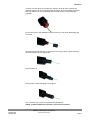
Whilst squeezing the red retainer in the direction of ARROWS A, pull in the
direction of ARROW B.
A
A
B
Your connector should now resemble the connector in the picture below.
Insert each contact pin until you feel a slight click. If you have inserted the contact
into the incorrect hole it can be removed at this point by simply pulling it out.
Please note there will be some resistance.
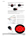
WindSonic (Option 2) RS422 10 Metre Cable Connections
Connections for the WindSonic connector are as follows:-
Green/White wire to Connector Pin 1
Orange/White wire to Connector Pin 2
White/Orange wire to Connector Pin 3
Brown/White wire to Connector Pin 4
White/Brown wire to Connector Pin 5
Blue/White wire to Connector Pin 6
White/Blue wire to Connector Pin 7
White/Green cut off at sleeve
1
8
7
2
9
3
4
6
5
Rear View of Connector
MetPak Pro Base Station User Manual
© Gill Instruments Ltd
Page 8
Last Change
22 April, 2013
Installation
Continue to insert all of the contacts you require. Once all of the contacts are
inserted squeeze the 2 red retainers (See Arrows A on previous page) into place.
NB. The retainer can only be pushed back into place if the contacts are fully
engaged.
Fit the connector to the WindSonic Sensor so that you can finish assembling the
connector.
Screw the back shell onto the connector until it is fully in place. Please note that
the final rotations can be slightly stiff.
Now screw the next part of the connector into place.
Now screw the cable-clamping nut into place.
The connector can now be removed from the WindSonic.
NOTE: To disassemble the connector, reverse this procedure.
Last Change
22 April, 2013
MetPak Pro Base Station User Manual
© Gill Instruments Ltd
Page 9
Installation
WindMaster and WindMaster Pro RS422 10 Metre Cable
Connections
The WindMaster uses the same range of connector as the WindSonic except for
being a 31 way type. Follow the WindSonic connector assembly procedure except
for:White/Brown wire to Connector Pin 1
Brown/White wire to Connector Pin 2
Green/White wire to Connector Pin 4
Blue/White wire to Connector Pin 5
White/Blue wire to Connector Pin 6
Orange/White wire to Connector Pin 11
White/Orange wire to Connector Pin 12
White/Green wire to Connector Pin 31
WindMaster 31 way Connector Pin outs
MetPak Pro Base Station User Manual
© Gill Instruments Ltd
Page 10
Last Change
22 April, 2013
Installation
WindSonic M (Heated) RS422 10 Metre Cable Connections to
the Heater Power Interface Box.
Note: See also the lid of the Heater Power Interface Box for Connection Details.
Cut off the contact pins connected to the MetPak Pro Base Station 10 Metre cable,
strip and solder wires. Connect wires to the Heater Power Interface box as follows:Remote Base Station
10 Metre Cable
White/Green
Green/White
Orange/White
White/Orange
Brown/White
White/Brown
Blue/White
White/Blue
No Connection
No Connection
Heater Power Supply
Heater Supply +ve
Heater Supply -ve
Heater Power
Interface Box
8 Way Terminal Block
8
7
6
5
4
3
2
1
No Connection
No Connection
WindSonic M
(Heated)
9 Way Connector
1
No Connection
2
3
4
5
6
7
8
9
Heater Power
Interface Box
4 Way Terminal Block
3
2
WindSonic M
(Heated)
9 Way Connector
8
9
WindObserver 70 (Enhanced Heated) RS422 10 Metre Cable
Connections to the Heater Power Interface Box.
Note: See also the lid of the Heater Power Interface Box for Connection Details.
Cut off the contact pins connected to the MetPak Pro Base Station 10 Metre cable,
strip and solder wires. Connect wires to the Heater Power Interface box as follows:-
Last Change
22 April, 2013
Remote Base
Station
10 Metre Cable
White/Green
Green/White
Orange/White
White/Orange
Brown/White
White/Brown
Blue/White
White/Blue
No Connection
No Connection
Heater Power
Interface Box
8 Way Terminal Block
8 or Screen Terminal Tag
7
6
5
4
3
2
1
No Connection
No Connection
WindObserver 70
(Enhanced Heated)
19 Way Connector
Cable Screen/Drain wires
M
R
D
P
C
U
V
A, E and H
B, F and G
Heater Power
Supply
Heater Power
Interface Box
WindObserver 70
(Enhanced Heated)
Heater Supply +ve
Heater Supply -ve
4 Way Terminal Block
3
2
19 Way Connector
A, E and H
B, F and G
MetPak Pro Base Station User Manual
© Gill Instruments Ltd
Page 11
Installation
Remote Base Communication Cabling
MetPak Pro Base Station has five communication connection options:
USB (using the 1.8m Gill USB cable, Part No. 1723-10-051).
RS232
RS422
RS485 (two wire point to point).
SDI-12 (Not with 3 axis WindMaster and WindMaster pro connected)
MetPak Pro Base Station has various Sensor Input connection options:
0-5v
4-20mA
PRT.
Digital Switch
Gill Wind Sensor via 10 Metre Cable (RS422 connection)
It is important that the cable is appropriate for the chosen connection option. The
following sections describe the recommended types and maximum lengths of cable
in each case.
NOTE. A 15-metre, 6-pair cable (wires stripped at each end) suitable for
RS232/RS422 or SDI-12 communication is available from Gill Instruments (Part
No. 1723-10-053).
Cable Type
Wire type:
24AWG
Wire size:
7x32 AWG.
Cable outer diameter:
6-8mm (to match the hub box gland).
For RS422/485 operation the cable should contain twisted pairs screened to match
the application.
The following table shows an example manufacturers’ reference; other
manufacturers’ equivalents can be used.
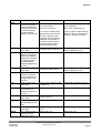
Table 2
Recommended Belden cable types
Application
No. of Pairs
SDI-12 or RS485
2
Belden Ref.
9729
Digital RS232
3
9503
Digital RS422
4
9504
Multiple External Sensors
6
9506
Cable length
The maximum cable length is dependent on the chosen communication method.
The following table shows the maximum cable lengths for the supported
communication protocols at the given baud rates, using the recommended cable. If
any problems of data corruption etc. are experienced, then a slower baud rate
should be used. Alternatively, a higher specification cable can be tried.
MetPak Pro Base Station User Manual
© Gill Instruments Ltd
Page 12
Last Change
22 April, 2013
Installation
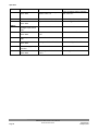
Table 3 Maximum cable lengths for supported communication and sensor network
Communication format
Baud rate
RS232
19200
Max. cable length
6.5M
RS422/485
19200
1000M
SDI-12
1200
90M
Not Applicable
Refer to user Analogue
Sensor data sheet
Not Applicable
Refer to user Analogue
Sensor data sheet
Not Applicable
Switch contact and cable
resistance to be less than
1k ohm
Not Applicable
Refer to user PRT data
sheet
0-5v Analogue Input
4-20mA Analogue Input
Digital Switch Input
PRT Input
Cabling (unused wires)
Any unused wires in the connecting cables should be connected to ground
preferably at the user equipment end.
Cabling protection
The Cable should be secured:
With cable clamps or equivalent at regular intervals such that the hub
box cable gland does not support the cable weight.
Away from the mounting bolts to prevent chaffing of the cable.
NOTE. Install appropriate strain relief support to the cable. If possible, pass the
cable through the mounting pole.
Earthing
To ensure correct operation and for maximum protection from lightning, a separate
lightning rod system is recommended to protect the system.
You can also earth the MetPak Pro Base Station through its mountings or by
connecting a grounding cable (minimum of 6mm² copper wire) to a spare MetPak
Pro Base Station metalwork bolt hole. Clean off any paint that might prevent a
good connection on the installation.
When you connect the communications cable ensure that the screen has a
connection to the hub box case.
The Junction Box accessory and Heater Power Interface Box has a plastic case,
hence ensure continuity of cable screens into and out of the boxes using the
common earthing terminals provided in the boxes.
Routing Cables through the Hub Box Glands
NOTE: The MetPak Pro Base Station Hub Box cable glands contain spring loaded
metal leaves that are designed to make a ground contact with cables that have an
overall braid screen. Care is therefore required when inserting and removing
cables through the glands to prevent damage to the metal leaves.
Last Change
22 April, 2013
MetPak Pro Base Station User Manual
© Gill Instruments Ltd
Page 13
Installation
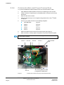
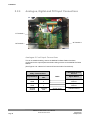
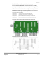
2.2.4
Communication and Power Connections
To connect the MetPak Pro Base Station Power and Communications cable:
1.
Open MetPak Pro Base Station’s hub box by unfastening the four screws.
2.
Locate connector J5 (see Figure 3). Carefully pull the connector off its circuit
board pins.
3.
Strip the cable wires to 8mm.
4.
Pass the cable through one of the gland nuts (please refer to the 2nd NOTE
on Page 8).
5.
Connect your cable as shown in the following diagrams:
Gill USB Cable
Figure 5
RS232
Figure 6
RS422
Figure 7
RS485
Figure 8
SDI-12
Figure 9
6.
Attach the cable’s screen wires to the terminal post (see Figure 3).
7.
After connection, securely tighten the gland nut to prevent moisture ingress.
NOTE. Ensure that MetPak Pro Base Station is configured for the chosen
communications method
J4 Pin 1
J4 Pin 8
J1 Pin 6
Figure 3
J5 Pin 8
J5 Pin 1
J5, showing RS232 to USB
Configuration Cable Wires
Internal view of the hub box (top circuit board removed).
MetPak Pro Base Station User Manual
© Gill Instruments Ltd
Page 14
Hex Terminal
Post
Last Change
22 April, 2013
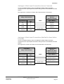
Installation
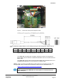
Figure 4
Hub Box with Analogue and Digital Pec fitted.
USB Lead Connection (COMMS set for RS232)
Connect to
Hub box J5
Connect MetPak Pro Base Station to a PC USB port using the Gill Configuration Cable 1723-10051.
J5 Pin
1
2
3
4
5
6
7
8
Colour
None
None
Yellow
Orange
None
None
Black
Red
Figure 5 Connection of Gill USB Cable (Part No. 1723-10-051)
This USB cable can supply the necessary minimum 5v power for configuring a
Base Station hub box and with a WindSonic/WindSonic M unit connected to the 10
Metre cable.
This USB cable can be used to power the Base Station with a WindObserver 70 or
WindMaster/WindMaster Pro connected to the 10 Metre cable.
NOTE:- If upon connecting the USB lead to a PC the driver is not found by the PC, then
the appropriate driver to match the PC Windows version may be downloaded from:http://www.ftdichip.com/Drivers/VCP.htm
NOTE. Ensure that MetPak Pro Base Station 10 Metre cable is terminated
before connecting the USB cable as sensor power is connected to the 10
Metre cable pins.
Last Change
22 April, 2013
MetPak Pro Base Station User Manual
© Gill Instruments Ltd
Page 15
Installation
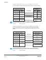
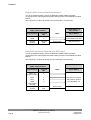
Digital Output RS232 Connections (COMMS set for RS232)
This is the MetPak Pro Base Station default communication configuration setting.
J5 Hub Box
8 Way Push fit Block
Terminal
Signal names
Nos.
3 Pair Cable
PC 9 Way D Type
Connector
Pin
Signal
No’s
Names
RS232 TX
RS232 RX
3
4
2
3
RXD
TXD
Signal Ground
2
5
Sig Gnd
Chasis Ground
Terminal
Post
NA
Chassis
Ground
Supply –ve
Supply +ve
7
8
Screen wires
–
+
DC Power
supply
NOTE. Ensure that MetPak Pro Base Station 10 Metre cable is terminated before
connecting dc power as sensor power is connected to the 10 Metre cable
Figure 6
RS232 connections
Digital Output RS422 Connections (COMMS set for RS422)
This is not the default communications setting; ensure the MetPak Pro Base
Station has been configured for this output requirement before wiring to a user
device.
J5 Hub Box
8 Way Push fit Block
Terminal
Signal Names
Nos.
RS422 to RS232 or
USB Converter
4 Pair Cable
Signal Names
RS422 TX +
RS422 TX –
6
3
RX +
RX –
RS422 RX +
RS422 RX –
TX +
TX –
Signal Ground
5
4
2
Chassis
Ground
Terminal
Post
Supply –ve
Supply +ve
7
8
Signal Ground
Screen wires
Chassis Ground
–
+
DC Power Supply
NOTE. Ensure that MetPak Pro Base Station 10 Metre cable is terminated before
connecting the DC power supply as sensor power is connected to the 10 Metre cable.
Figure 7
RS422 connections
MetPak Pro Base Station User Manual
© Gill Instruments Ltd
Page 16
Last Change
22 April, 2013
Installation
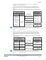
Digital Output RS485S 2 Wire Point to Point Connections
(COMMS set for RS485P2W)
This is not the default communications setting; ensure the MetPak Pro Base
Station has been configured for this output requirement before wiring to a user
device.
Note that it is not possible to network other devices on this 2-wire RS485
link.
J5 Hub Box
8 Way Push fit Block
Terminal
Signal Names
Nos.
RS485 to RS232
or USB Converter
2 Pair Cable
Signal Names
RS485 TX +
RS485 RX+
RS485 TX –
RS485 RX –
6
5
3
4
RS485TX/RX+
Signal Ground
2
Signal Ground
Chassis
Ground
Terminal
Post
Supply -ve
Supply +ve
7
8
RS485TX/RX–
Screen wires
Chassis ground
–
+
DC Power
Supply
NOTE. Ensure that MetPak Pro Base Station 10 Metre cable is terminated before
connecting the DC power supply as sensor power is connected to the 10 Metre cable.
Figure 8
RS485 Connections
Digital Output SDI-12 Connections (COMMS set for SDI12)
This is not the default communications setting; ensure the MetPak Pro Base
Station has been configured for this output requirement before wiring to a user
device.
(Note SD-12 communications is not applicable with a 3 axis sensor connected to
the Base station).
J5 Hub Box
8 Way Push fit Block
Signal
Terminal
Names
Nos.
SDI-12 Device
2 Pair Cable
Signal Names
SDI-12
1
SDI-12
Signal Ground
2
Signal Ground
Chassis
Ground
Terminal
Post
Supply –ve
Supply +ve
7
8
Screen wires
Chassis Ground
–
+
DC Power
Supply
NOTE. Ensure that MetPak Pro Base Station 10 Metre cable is terminated before
connecting the DC power supply as sensor power is connected to the 10 Metre cable.
Figure 9
Last Change
22 April, 2013
SDI-12 connections
MetPak Pro Base Station User Manual
© Gill Instruments Ltd
Page 17
Installation
2.2.5
Analogue, Digital and PRT Input Connections
J7 Terminal 1
J9 Terminal 1
J8 Terminal 1
Analogue 0-5 volt Input Connections
This is not a default setting; ensure the MetPak Pro Base Station has been
configured for this input requirement before wiring sensors to the MetPak Pro Base
Station.
(See Figures 5 to 9 above for Power and Communication Connections).
J9 Hub Box
8 Way Terminal Block
Terminal
Signal Names
Nos.
VI 1
GND
VI 2
GND
Chassis
Ground
1
2
3
4
Terminal
Post
0-5V Voltage Output
Sensors
Cable
Signal Names
Screen wires
Voltage Out 1
Ground
Voltage Out 2
Ground
Chassis Ground
MetPak Pro Base Station User Manual
© Gill Instruments Ltd
Page 18
Last Change
22 April, 2013
Installation
Analogue 4-20mA Input Connections (Sensor Powered)
This is not a default setting; ensure the MetPak Pro Base Station has been
configured for this input requirement before wiring sensors to the MetPak Pro Base
Station.
See Figures 6 to 10 above for Power and Communication Connections).
J9 Hub Box
8 Way Terminal Block
Signal Names
Terminal
Nos.
II 1
GND
II 2
GND
Chassis
Ground
6
2
8
4
Terminal
Post
4-20mA Current
Sensors
(Sensor Powered)
Cable
Signal Names
Screen wires
Current 1
Ground
Current 2
Ground
Chassis Ground
Analogue 4-20mA Input Connections (MetPak Pro Base Station
Powered)
This is not a default setting; ensure the MetPak Pro Base Station has been
configured for this input requirement before wiring sensors to the MetPak Pro Base
Station.
See Figures 5 to 9 above for Power and Communication Connections).
J9 Hub Box
8 Way Terminal Block
Last Change
22 April, 2013
Signal Names
Terminal
Nos.
II 1
IL Power
II 2
IL Power
Chassis
Ground
6
5
8
7
Terminal
Post
4-20mA Current
Sensors
(MetPak Pro Base
Station Powered)
Cable
Signal Names
Screen wires
Current 1
Sensor Power In
Current 2
Sensor Power In
Chassis Ground
MetPak Pro Base Station User Manual
© Gill Instruments Ltd
Page 19
Installation
Digital Switch Connection (Rain Gauge)
This is not a default setting; ensure the MetPak Pro Base Station has been
configured for this input requirement before wiring sensors to the MetPak Pro Base
Station.
See Figures 5 to 9 above for Power and Communication Connections).
J8 Hub Box
2 Way Terminal Block
Terminal
Signal Names
Nos.
DIG 1
GND
Chassis
Ground
2
1
Terminal
Post
Digital Switch e.g.
Rain Bucket
Cable
Signal Names
Switch Contact
Return Switch Contact
Screen Wire
Chassis Ground
Platinum Resistance Thermometer (PRT) Input
This is not a default setting; ensure the MetPak Pro Base Station has been
configured for this input requirement before wiring sensors to the MetPak Pro Base
Station.
See Figures 5 to 9 above for Power and Communication Connections).
J7 Hub Box
4 Way Terminal Block
Terminal
Signal Names
Nos.
PWR +ve
(Power to PRT)
PRT+
PRTGND
(PRT Power
Ground)
Chassis
Ground
PRT Sensor
Cable
PRT Excitation +ve
1
2
3
4
Terminal
Post
PRT Sense + Output
PRT Sense - Output
PRT Excitation -ve
Screen Wire
MetPak Pro Base Station User Manual
© Gill Instruments Ltd
Page 20
Signal Names
Chassis Ground
Last Change
22 April, 2013
Installation
2.2.6
MetPak Pro Base Station System Connections
Example Non Heated Wind Sensor System
A typical MetPak Pro Base Station system with a non-heated wind sensor system
might look like the following illustration.
Optional external
supply input cable
Last Change
22 April, 2013
Data communications and
MetPak Pro Base
Station/Sensor Power Cable.
MetPak Pro Base Station User Manual
© Gill Instruments Ltd
Page 21
Installation
Example Heated Wind Sensor System
A typical MetPak Pro Base Station system with a heated wind sensor system might
look like the following illustration.
Wind Sensor
Heater Supply
Cable
Figure 10
Optional external
supply input cable
Data communications
and MetPak Pro Base
Station/Sensor Power
Cable.
MetPak Pro Base Station Example System Pictures
MetPak Pro Base Station User Manual
© Gill Instruments Ltd
Page 22
Last Change
22 April, 2013
Installation
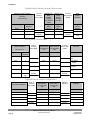
MetPak Pro Base Station Junction Box Accessory
As part of a MetPak Pro Base Station system Gill Instruments can provide a
Junction Box containing a pcb with removable terminal connectors and optional
mounting hardware to provide a means of connecting external analogue, PRT and
Digital sensors and MetPak Pro Base Station wiring at a convenient common point.
It is not intended that external Wind Sensor wiring be routed through this box.
Alternatively the pcb with removable terminal connectors can be supplied as a
standalone item for mounting in a customer supplied box.
Junction Box parts if required are:
1723-PK-201
Junction Box with internal terminating pcb.
1723-PK-202
Terminating pcb (to mount in customer box).
1723-PK-204
Pack of 4 feet for Panel Mounting the Junction Box.
1723-PK-203
Pack of 4 brackets for Pole Mounting the Junction Box.
Junction Box 1723-PK-201 (containing Terminating pcb 1723-PK-202)
Junction Box terminating pcb circuit track layout
Last Change
22 April, 2013
MetPak Pro Base Station User Manual
© Gill Instruments Ltd
Page 23
Installation
Junction Box Terminal Block Connections
Note that the Junction box glands will accept cables with an outer diameter
between 3-10mm. If a smaller diameter cable is to be used bulk out with heat
shrink or suitable sleeve to ensure the gland can secure the cable and provide an
environmental seal.
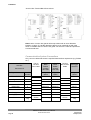
Communication System Connections
Only connect cables that meet the required data interface requirement (e.g. RS232
etc.).
MetPak Pro Base Station
Hub Box
Hub to
Junction
Box Cable
Connector J5
MetPak Pro
Base
Station
Junction
Box TB5
MetPak Pro
Base
Station
Junction
Box TB6
Junction
Box to User
Cable
User
PC/Logger
Interface
Signal Name
Terminal
Number
Signal
Name
Signal
Name
Signal
Name
SDI-12 TX/RX
1
SDI-12
SDI-12
SDI-12
Signal 0v
2
SIG 0v
SIG 0v
SIG 0v
RS232/422/485 TX-
3
232/422 T-
232/422 T-
232/422 R-
RS232/422 RX-
4
232/422 R-
232/422 R-
232/422 T-
RS422 RX+
5
RS422 R+
RS422 R+
422 T+
RS422/485 TX+
6
RS422 T+
RS422 T+
422 R+
Supply 0v
7
PWR 0v
PWR 0v
PWR 0v
Supply +ve
8
PWR +
PWR +
PWR +
Chassis
Terminal
Tag
Screen Tag
Screen Tag
Screen
MetPak Pro Base Station User Manual
© Gill Instruments Ltd
Page 24
Screen
Screen
Tag
Last Change
22 April, 2013
Installation
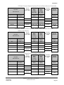
4-20mA Current Sensor System Connections (Sensor Powered)
MetPak Pro Base Station
Hub to
Junction
Box Cable
Hub Box
Connector J9
MetPak Pro
Base
Station
Junction
Box TB9
MetPak Pro
Base
Station
Junction
Box TB10
Junction
Box to User
Cable
User
Current
Interface
Signal Name
Terminal
Number
Signal
Name
Signal
Name
Signal
Name
II1
6
II1
II1
II1
GND
2
GND
GND
GND
II 2
8
II 2
II 2
II2
GND
4
GND
GND
GND
Chassis
Terminal Tag
Screen Tag
Screen Tag
Screen
Screen
Screen
Tag
4-20mA Current Sensor System Connections (MetPak Pro Base
Station Powered)
MetPak Pro Base Station
Hub to
Junction
Box Cable
Hub Box
Connector J9
MetPak Pro
Base
Station
Junction
Box TB9
MetPak Pro
Base
Station
Junction
Box TB10
Junction
Box to User
Cable
User
Current
Interface
Signal Name
Terminal
Number
Signal
Name
Signal
Name
Signal
Name
II1
6
II1
II1
II1
IL PWR
5
IL PWR
IL PWR
IL Power
II 2
8
II 2
II 2
II2
IL PWR
7
IL PWR
IL PWR
IL Power
Chassis
Terminal Tag
Screen Tag
Screen Tag
Screen
Screen
Screen
Tag
Junction
Box to User
Cable
User
Voltage
Interface
0-5 Volt Voltage Sensor System Connections
MetPak Pro Base Station
Hub to
Junction
Box Cable
Hub Box
Connector J9
MetPak Pro
Base
Station
Junction
Box TB9
MetPak Pro
Base
Station
Junction
Box TB10
Signal Name
Terminal
Number
Signal
Name
Signal
Name
Signal
Name
VI 1
1
VI 1
VI 1
V Out 1
GND
2
GND
GND
Ground
VI 2
3
VI 2
VI 2
V Out 2
GND
4
GND
GND
Ground
Chassis
Terminal Tag
Screen Tag
Screen Tag
Last Change
22 April, 2013
Screen
Screen
Screen
Tag
MetPak Pro Base Station User Manual
© Gill Instruments Ltd
Page 25
Installation
Digital Switch Sensor System Connections
MetPak Pro Base Station
Hub to
Junction
Box Cable
Hub Box
Connector J8
MetPak Pro
Base
Station
Junction
Box TB8 or
TB8A
MetPak Pro
Base
Station
Junction
Box TB3
Junction
Box to User
Cable
User
Switch
Interface
Signal Name
Terminal
Number
Signal
Name
Signal
Name
Signal
Name
DIG 1
2
DIG 1
DIG 1
Contact
GND
1
GND
GND
Contact
Chassis
Terminal Tag
Screen Tag
Screen Tag
Screen
Screen
Screen
Tag
PRT System Connections
MetPak Pro Base
Station Hub Box
Hub to
Junction
Box Cable
Connector J7
MetPak Pro
Base Station
Junction Box
TB7
MetPak Pro
Base Station
Junction Box
TB4
Junction
Box to User
Cable
User PRT
Interface
Signal Name
Terminal
Number
Signal Name
Signal Name
Signal Name
PWR+ve
1
PWR+ve
PWR+ve
PRT Excitation
+ve
PRT+
2
PRT+
PRT+
PRT Sense
+ Output
PRT-
3
PRT-
PRT-
PRT Sense
- Output
PRT GND
4
GND
GND
PRT Excitation
-ve
Chassis
Terminal
Tag
Screen Tag
Screen Tag
Screen
Screen
Screen Tag
External Power Supply Connections
MetPak Pro
Base Station
Junction Box
TB1
MetPak Pro
Base Station
Junction Box
TB2
Signal Name
Signal Name
Signal Name
Signal Name
PSU1 +ve
PSU1 +ve
PSU1 +ve
PSU1 +ve
PSU1 –ve
PSU1 –ve
PSU1 –ve
PSU1 –ve
PSU2 +ve
PSU2 +ve
PSU2 +ve
PSU2 +ve
PSU2 -ve
PSU2 -ve
PSU2 -ve
PSU2 -ve
Screen Tag
Screen Tag
User Power Supplies
Chassis
User to
Junction
Box Cable
Screen
MetPak Pro Base Station User Manual
© Gill Instruments Ltd
Page 26
Cable to
Sensors
Screen
User Sensor
Supplies
Screen Tag
Last Change
22 April, 2013
Installation
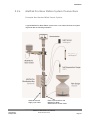
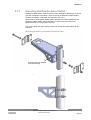
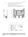
2.2.7
Mounting MetPak Pro Base Station
MetPak Pro Base Station uses a mounting clamp suitable for attaching to a vertical
pipe with a diameter of 30-58mm. When mounting the MetPak Pro Base Station,
consider the position, orientation and alignment of the unit.
Note that the mounting pipe should first be degreased and when assembling the
MetPak Pro Base Station clamp assembly the outer clamp nuts need to be
tightened evenly to a torque figure of 3 Nm.
The moving plate part of the clamp needs to be reversed for poles below 38 mm
diameter.
Mounting Bracket Assembly Exploded View
Earthing Point for supplied
screw/washer/tag
Mounting Bracket Assembled View
Last Change
22 April, 2013
MetPak Pro Base Station User Manual
© Gill Instruments Ltd
Page 27
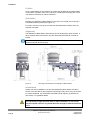
Installation
Position
It is the responsibility of the customer to ensure that the MetPak Pro Base Station
is mounted in a position clear of any structure, including the mounting post, which
may obstruct the airflow or induce turbulence.
Orientation
Normally, the MetPak Pro Base Station is mounted on a vertical pole, ensuring a
horizontal Measuring Plane (see Figure 11).
For indoor use the unit may be mounted with the Measurement Plane set to any
required orientation.
Alignment
The MetPak Pro Base Station Wind Sensor should be aligned to point to North, or
other required reference direction. See the associated Wind Sensor manual for
details.
Note. It is usually simpler to work first with a compass at ground level and identify a
suitable landmark and its bearing.
Figure 11
Mounting and Dimensions for MetPak Pro Base Station
Interference
Always check the installation to ensure the MetPak Pro Base Station and Wind
sensor is not affected by other equipment operating locally, which may not conform
to current standards, e.g. radio/radar transmitters, boat engines, generators etc.
See Para 2.1 for guideline details.
CAUTION. Do NOT mount the MetPak Pro Base Station and Wind Sensor in
close proximity to high-powered radar or radio transmitters. A site survey
may be required if there is any doubt about the strength of external electrical
noise.
MetPak Pro Base Station User Manual
© Gill Instruments Ltd
Page 28
Last Change
22 April, 2013
Installation
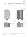
2.2.8
Mounting MetPak Pro Base Station Junction Box
The MetPak Pro Base Station Junction Box comes with two mounting arrangement
options: -
Junction Box Pole Mount
Using Gill Instruments part 1723-PK-203 Pole Mount brackets set for Junction Box.
Last Change
22 April, 2013
MetPak Pro Base Station User Manual
© Gill Instruments Ltd
Page 29
Installation
Junction Box Panel or Wall Mount
Using Gill Instruments part 1723-PK-204 Pack of 4 feet for Wall or Panel Mounting
the Junction Box.
Panel/Wall
Mounting foot
MetPak Pro Base Station User Manual
© Gill Instruments Ltd
Page 30
Last Change
22 April, 2013
Installation
2.2.9
Mounting MetPak Pro Base Station Heater
Power Interface Box (Optional Item)
This Interface box is included with orders for:MetPak Pro Base Station 1723-2A-3-211 (with Heated WindSonic M).
MetPak Pro Base Station 1723-2A-4-311 (with Enhanced Heated WindObserver
70).
Last Change
22 April, 2013
MetPak Pro Base Station User Manual
© Gill Instruments Ltd
Page 31
3. Operation
This section provides an overview of the operation of the MetPak Pro Base Station.
For more detailed information about any of the steps, use the references to other
sections of this manual.
3.1
1.
Start Guide
Decide how you are going to connect MetPak Pro Base Station to your PC
or communications network. MetPak Pro Base Station supports the following
options:
USB connection using Gill’s RS232 to USB 1.8M configuration cable
(includes integral 5V power supply for WindSonic connections only)
compatible with MetSet. To order, contact your dealer quoting part
number: 1723-10-051).
NOTE. You could use an equivalent RS232-USB adapter such as
EasySynch RS232 to USB adaptor.
RS232 connection using standard cable and PC COM port. Separate
12V to 30V dc power supply also required (compatible with MetSet).
RS422 using RS232 converter (compatible with MetSet).
RS485 2 wire point to point (not compatible with MetSet).
SDI-12 connection (note SDI-12 is not compatible with MetSet
Software).
NOTE. MetPak Pro Base Station is pre-configured for RS232
communication (factory setting). If you want to use an alternative
communication protocol, you will need to set up the unit using an
RS232 connection (with an appropriately wired cable), change the
setting, shut the unit down, attach a cable for the new communication
type, and then restart the unit.
2.
Check that you have the following:
MetPak Pro Base Station unit (Part No.1723-2A-X-111).
A suitable Gill Wind Sensor (See page 6).
Gill MetView and MetSet Software and Manual supplied on the CD.
If any parts are missing, please contact your dealer.
Last Change
22 April, 2013
3.
Connect the 10 Metre RS422 cable to the appropriate Wind Sensor
connector and Wind Sensor or Heater Power Interface Box and Wind
Sensor.
4.
Open the Base Station hub box by unfastening the four retaining screws.
Locate the connector: J5 (see Page 9, Figure 3). Carefully pull the connector
block from its pins.
5.
Prepare the communications cable by stripping the wires to a length of 8mm.
Feed the prepared cable through one of the two available ports on the side
of the connection box (please refer to the 2nd NOTE on Page 8).
MetPak Pro Base Station User Manual
© Gill Instruments Ltd
Page 33
Operation
6.
Connect the cable to J5 as described on page 10 for your chosen
communications method.
7.
Carefully press J5 onto its circuit board pins.
8.
If connecting Analogue inputs, the Digital Input or a PRT strip cable wires
and connect to respective connectors J9, J8 and J7 in the hub box.
9.
Tighten the gland on the connection ports to seal the cables in place.
Replace the top on the connection box.
10.
If you are carrying out a bench test, continue to step 17. When you have
finished testing, return to Step 13.
11.
Ensure that if you are using a mounting pole that it has been degreased in
the area where the MetPak Pro Base Station will be positioned.
12.
Position the MetPak Pro Base Station against the mounting post (see page
22), replace the mounting bracket and tighten sufficiently to hold the unit in
place but allowing it to be rotated or moved up and down the pole.
13.
Install the Wind Sensor in accordance with the appropriate Wind Sensor
manual
14.
Check the Wind Sensor orientation and alignment of the unit instructed in
the Wind sensor Manual.
15.
Check the height of the Wind Sensor and MetPak Pro Base Station and
ensure that they are clear of any obstructions, including the mounting post
that could interfere with their measurements.
16.
Tighten the MetPak Pro Base Station mounting bracket nuts evenly to a
torque of 3Nm to hold the unit firmly in place.
17.
Connect the communications cable to your PC or network device.
18.
Connect Analogue, Digital or PRT cables to respective instruments.
19.
Place the MetPak Pro Base Station CD in your PC’s CD drive and install
MetSet and MetView.
MetPak Pro Base Station User Manual
© Gill Instruments Ltd
Page 34
Last Change
22 April, 2013
Operation
3.2
MetView
MetView Software allows you to view the MetPak Pro Base Station data graphically
and has a simple data logging facility.
Before you can use MetView, check that MetPak Pro Base Station is correctly
connected to a Serial COM port or USB COM port on your PC.
NOTE: MetView is compatible with RS232 and RS422 connected units only.
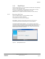
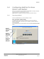
3.2.1
Opening MetView
Click on the MetView button on your PC’s desktop or choose:
Start > Programs > MetView > MetView
The MetView Control Centre window is displayed
Scan Button– If MetPak Pro Base Station transmit and receive wires are
connected to the PC then use the Scan button to connect to MetView.
Connection is Receive Only Tick Box – Use if the MetPak Pro Base Station
connection to the PC has only transmit wires connected and a MetSet version of its
current device settings is available to upload to MetView. Select ‘Connection is
Receive only’ tick box and click on the Scan button. Upload a MetSet generated
Device file from a PC location as directed.
Figure 12
Last Change
22 April, 2013
Opening MetView Screen
MetPak Pro Base Station User Manual
© Gill Instruments Ltd
Page 35
Operation
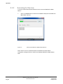
3.2.2
Scanning for Devices
To set up communicate between MetView and a connected MetPak Pro Base
Station:
1.
Click on the Scan button to search the available COM ports for MetPak Pro
Base Station devices.
Figure 13
Scanning for MetPak Pro Base Station Devices
When a device is found, MetView obtains the MetPak Pro Base Station
configuration settings and then retrieves and displays MetPak Pro Base Station
data.
MetPak Pro Base Station User Manual
© Gill Instruments Ltd
Page 36
Last Change
22 April, 2013
Operation
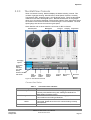
3.2.3
The MetView Console
When connected correctly, MetView displays its data-monitoring console. This
consists of gauges showing: Wind Direction, Wind Speed, Pressure, Humidity,
Temperature, PRT, Analogue Input 1 and Analogue Input 2. There are also digital
readouts of Dew Point and Digital Input 1. Buttons beneath each of the gauges
allow you to choose the displayed units and other options. Each gauge also shows
the maximum and minimum values recorded during the current session. The wind
speed gauge also shows the maximum gust speed.
Note: MetView will not show data if the unit is set for SDI-12 format.
Wind Direction
Wind Speed
Pressure
Humidity
Temperature
Disconnect
button
Dew Point
Averaging
options
Connection
Status
indicators
(see Table
below)
Firmware Version
and Unit ID
Load
Settings
button
Save
Settings
button
Default
Settings
button
Logging
button
Figure 14 The MetView Console
Max/Min
Markers
Connection Status
Table 4
Reading
Green Background Tick
Red Background Cross
1.00Hz
Thu 31 Jan 2013 11:25:06
Last Change
22 April, 2013
Connection status indicators
Function
Indicates MetPak Pro Base Station logging or communicating
correctly with MetView along with reading the MetPak Pro
Base Station firmware version.
Indicates MetPak Pro Base Station not logging or
connected/communicating to MetView.
Indicates the output rate of the MetPak Pro Base Station when
connected. Reads when the unit is communicating correctly
with MetView.
Real Time PC date and time indication.
MetPak Pro Base Station User Manual
© Gill Instruments Ltd
Page 37
Operation
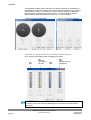
If the MetPak Pro Base Station has been purchased configured for WindMaster or
WindMaster Pro operation MetSet can be used to set the Wind Data output string to
read in Polar and W or U, V and W output. When MetView reads the 3 axis Wind
data it will either be displayed in Polar and W or U, V and W format as follows:Note MetView cannot switch between Polar and U, V and W displays.
3 Axis Polar and W Wind Display
3 Axis U, V and W Wind Display
MetPak Pro Base Station User External Sensor Display
PRT, Analogue and Digital inputs are displayed as follow:-
PRT
Input
AN1
Input with
user defined
title ‘SUN’
AN2
Input
DIG 1
Input
Typically used with
a Rain Sensor
Note. The order in which the instruments are shown in the MetView display reflects
the order in which the instrument data appears in the MetPak Pro Base Station
data string.
MetPak Pro Base Station User Manual
© Gill Instruments Ltd
Page 38
Last Change
22 April, 2013
Operation
3.2.4
MetView Console Display Options
MetView Console buttons can convert data from the MetPak Pro Base Station to
read different units or scale settings. This does not alter the actual MetPak Pro
Base Station configuration.
Units shown in bold denote default settings
Table 5
MetView scale and unit options
Gauge
Wind Direction
Wind Speed
Markers
Wind Speed
Pressure
Humidity
Temperature &
Dew Point
PRT
AN1
AN2
DIG1
Table 6
Setting
Real Time
2 Min
10Min
Table 7
Setting
Off
On
Reset
Table 8
Setting
Save Settings
Load Settings
Default Settings
Last Change
22 April, 2013
Function
Use buttons to choose from two display styles: NSEW or
Maritime
Use buttons to add markers on the gauge for Max/Min or
Max Gust.
Use buttons to choose from five wind speed units: m/s,
kph, mph, kts, fpm
Use buttons to choose from pressure scales: hPa, mbar,
inHg, mmHg
Displays Max and Min values during current session in %
Use buttons to choose from three temperature scales: °C,
°F, K
Use buttons to choose from three temperature scales: °C,
°F, K
Buttons displayed will depend on Analogue input type
selected.
Buttons displayed will depend on Analogue input type
selected.
Typically for Rain, reads total rainfall since connected,
buttons available for inches or millimetres and a reset
button.
MetView averaging options
Function
Choose this button for no averaging
Select for 2 minute rolling average of all sensor readings
except DIG1
Select for 10 minute rolling average of all sensor readings
except DIG1
Max/min markers
Function
Maximum and Minimum Markers on all gauges turned off
Maximum and Minimum Markers on all gauges turned on
Reset all Gauge Maximum/Minimum Markers and all
digital Maximum/Minimum reading at will
MetView Screen Settings Options
Function
Will Save all the current MetView screen settings to a file
for later retrieval if required.
Will load and update the MetView screen with a previously
saved setting.
Will return all MetView screen settings to factory default.
MetPak Pro Base Station User Manual
© Gill Instruments Ltd
Page 39
Operation
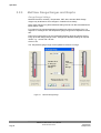
3.2.5
MetView Gauge Ranges and Graphs
Gauge Range Settings.
MetView Pressure, Humidity, Temperature, PRT, AN1, AN2 and DIG1 Gauge
ranges may be altered to view changes in conditions more visibly.
Note, these changes only affect MetView settings and do not affect the MetPak Pro
Base Station output.
For instance if the typical temperature measurement range required is from +10
degrees to +40 deg C then the temperature gauge range can be adjusted to reflect
this.
Place the mouse pointer over the Temperature display gauge and double click to
bring up the Set Gauge Range screen. Change Max and Min readings to required
values, e.g. +10 min and +40 max.
Click on Set.
The Temperature gauge range will be updated to reflect the change.
Double Click
to bring up
Set Gauge
Range.
Figure 15
MetView Gauge Range
MetPak Pro Base Station User Manual
© Gill Instruments Ltd
Page 40
After
changing
the
Range.
Last Change
22 April, 2013
Operation
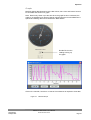
Graphs
MetView allows data detected over the last minute, last 1 hour and last 24 hours to
be accessed and shown on a graph.
Note. Data is only shown up to the time when the graph function is selected; the
graph is not updated once opened. Data is collected from the time that MetView is
opened and reading data from a MetPak Pro Base Station.
Double Click on the
reading to bring up
the graph.
Click on the Last Min, Last Hour or Last 24 Hours buttons as required to view data.
Figure 16
Last Change
22 April, 2013
MetView Graph
MetPak Pro Base Station User Manual
© Gill Instruments Ltd
Page 41
Operation
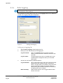
3.2.6
Data logging
NOTE. MetView logs data based on the MetPak Pro Base Station configuration not
on the MetView console settings.
To log MetPak Pro Base Station data, click on the Logging button on the MetView
console. The Logging dialog box is displayed.
Figure 17
Setting up data logging
Setting up a logging file
1.
Select Enable Logging to start logging to a file.
2.
Identify the name and location for the logging file:
3.
Log File location
Click on the Browse button to identify the folder
where you want to store the data file. Enter the name
of the file.
Log file header
if required type some notes on the data that is to be
recorded which will appear at the top of the saved
data log file.
Choose from the following additional options:
Log File Rotation
Set up segmented logging with each logged file length
determined by the number entered in the text box
below. The figure 3600, for example, means that each
log file length will be 3600 lines of data. Maximum
entries per log file is limited to 65535 and a maximum
of 2048 log files can be created.
Add Timestamp
Adds the date and time to the logged data file taken
from the PC clock.
MetPak Pro Base Station User Manual
© Gill Instruments Ltd
Page 42
Last Change
22 April, 2013
Operation
To start logging
1.
Check that the Enable Logging option is selected.
2.
Click on the OK button to commence logging and return to the console.
Note. To show that data is being recorded, the Logging button’s icon changes to a
green tick:
Logging active
Logging stopped
To stop logging
To turn off logging:
Last Change
22 April, 2013
1.
Click on the Logging button on the MetView console. Clear the Enable
Logging check box.
2.
Click on the OK button. If logging has stopped, the Logging button shows a
red background cross instead of the green background tick (see above).
MetPak Pro Base Station User Manual
© Gill Instruments Ltd
Page 43
Operation
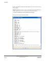
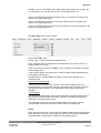
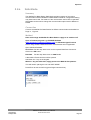
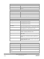
Understanding Logged Data
Logged data is stored to a file with a .log extension. This can be viewed in any
text/HTML editor or spreadsheet application.
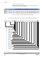
Figure 19 A typical 2 Axis data log (viewed in Windows Notepad)
Each entry in the default reporting order consists of the following (2 axis data illustrated):
000005, Fri 11 January 2013 15:18:55, Q,244,000.03,1017.3,049.2,+021.4,+10.3,+040.50,+000.06,+000.04,0000.000,+11.6,00, 77
Line Number
Date/time stamp
Start character
Node letter
Wind direction
Wind speed
Pressure
Humidity
Temperature
Dewpoint
PRT
An I/P 1
An I/P 2
Dig I/P
Supply Voltage
Status Code
End character
Checksum
MetPak Pro Base Station User Manual
© Gill Instruments Ltd
Page 44
Last Change
22 April, 2013
Operation
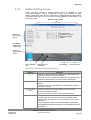
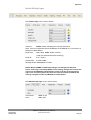
3.3
MetPak Pro Base Station
Configuration
MetPak Pro Base Station can be configured using Gill MetSet software.
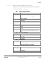
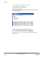
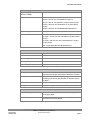
The default configuration settings are listed in the following table.
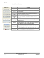
Table 9
Setting
Function
Comms Levels
Baud Rate
Data Connection
Node ID
Output rate
Message Mode
ASCII Set Up
North Alignment
Sensor WindSpeed
Wind Speed Units
Temperature Sensor
Temperature Units
Dewpoint Sensor
Dewpoint Units
Pressure Sensor
Pressure Units
Humidity Sensor
Humidity Units
Report Format
RS232
19200
Data Bits 8, Parity None, Stop Bits 1, Flow Control None.
Q
1Hz
Continuous
Carriage return and line feed, Echo on
0
On
MS (Metres/Second)
On
C (Degrees Celsius)
On
C (Degrees Celsius)
On
Hecto Pascals
On
%
Node, Polar (Wind Direction and Wind Speed), Pressure,
Humidity, Temperature, Dewpoint, PRT, AN1, AN2, DIG1,
Volts, Status, Checksum.
On
On
On
On
On
C (Degrees Celsius)
Not Configured
#
Not Configured
Status Message Output
Report Message Output
Units Message Output
Inputs Message Output
PRT Sensor
PRT Units
AN1 Sensor Type
AN1 Units
AN1 Analogue Input
Type
AN1 Substitute Name
AN2 Sensor Type
AN2 Units
AN2 Analogue Input
Type
AN2 Substitute Name
DIG1 Sensor Type
DIG1 Units
DIG1 Digital Count
DIG1 Substitute Name
Output Sentence
Last Change
22 April, 2013
Default configuration settings
Not Configured
#
Not Configured
Not Configured
#
Not Configured
Comma Separated Variable
MetPak Pro Base Station User Manual
© Gill Instruments Ltd
Page 45
Operation
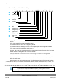
Example Default 2 Axis Data String:
<STX>Q,014,000.06,1011.2,042.1,+023.0,+009.4,,#,#,#,+04.9,00,<ETX>40 & (CR,LF)
STX
Node letter
Wind direction
Wind speed
Pressure
Humidity
Temperature
Dewpoint
PRT
Analogue Input 1
Analogue Input 2
Digital Input 1
Supply voltage
Status code
ETX
Checksum
Carriage Return/Line Feed
NOTES:
<STX> is the Start of String character (ASCII value 2).
,, is the default output for PRT until configured by MetSet.
# is the default output for Analogue Inputs 1 & 2 and Digital Input 1 until configured by MetSet.
<ETX> is the End of String character (ASCII value 3).
Checksum, the 2 digit Hex Checksum sum figure is calculated from the Exclusive OR of the bytes
between (and not including) the STX and ETX characters.
Example MetPak Pro Base Station Data String all Sensors Configured:
With 2 Axis wind sensor
Q,249,000.01,1017.3,049.2,+021.4,+010.3,+040.45,+000.06,+000.04,0000.000,+11.6,00, 7C
With 3 Axis wind Sensor
MetSet is used to set 3 axis wind readings for Wind Direction and Speed (Polar) and W readings.
Q,249,000.03,+000.02,1013.5,042.9,+022.0,+008.8,+040.45,+000.06,+000.04,0000.000,+11.6,00, 50
MetSet is used to set 3 axis wind readings for U, V and W readings.
Q,+000.01,-000.02,+000.00,1013.4,043.0,+022.1,+009.0,+040.45,+000.06,+000.04,0000.000,+11.6,00, 74
NOTE. Switch on Time. Upon switching on the MetPak Pro Base Station, allow
9.5 seconds to elapse before data is output. If powering Wind Sensors
separately then take individual sensor start up times into consideration.
MetPak Pro Base Station User Manual
© Gill Instruments Ltd
Page 46
Last Change
22 April, 2013
Operation
3.4
Configuring MetPak Pro Base
Station with MetSet
Before you use MetSet check that MetPak Pro Base Station is correctly connected
to a Serial COM port or USB COM port on your PC.
NOTE: MetSet is compatible with RS232 and RS422 connected units only.
3.4.1
Opening MetSet
Click on the MetSet button on your PC’s desktop or choose:
Start > All Programs > MetSet > MetSet
The MetSet Control Centre window is displayed. If you have more than one
MetPak Pro Base Station connected to your PC, MetSet, by default, selects the
first device detected.
For most applications it is recommended to click on the MetSet Connect and Read
button.
Connect the
MetPak Pro
output to MetSet
and read its
configuration
settings
Connect the
MetPak Pro
output to MetSet
without reading
its configuration
settings
Not Used
Disconnect
MetPak Pro and
create MetPak
Pro device
settings using
MetSet Offline
MetSet supported products list
Figure 18
Last Change
22 April, 2013
Opening MetSet Screen
MetPak Pro Base Station User Manual
© Gill Instruments Ltd
Page 47
Operation
MetSet interrogates the MetPak Pro Base Station and returns a summary of the
device settings.
Note that MetSet also saves a copy of this screen to the connected PC as a
Session Report File that can be accessed from the following destination.
C:\Program Files(X86)\Gill Instruments\MetSet\SessionReports
Close this screen to go to the Editing screens.
MetPak Pro Base Station User Manual
© Gill Instruments Ltd
Page 48
Last Change
22 April, 2013
Operation
3.4.2
MetSet Editing Screen
When connected correctly a MetSet editing screen is available to read
configuration settings, change configuration settings, save MetPak Pro Base
Station configuration settings to a PC file location, upload MetPak Pro Base Station
configuration settings from a PC file and view the MetPak Pro Base Station raw
data string output.
MetPak Pro Editing Pages
Move mouse over
exclamation or question
marks to read setting
comment
MetPak Pro
Device Setting
Options
View MetPak
Pro Raw Data
Output String
Return to
opening MetSet
Screen
Source of MetSet
Data
Serial Number
Firmware Version
and Unit ID
Connection Status
MetSet Connection Status Information.
Last Change
22 April, 2013
Reading
Function
ONLINE
ONLINE in green indicates the MetPak Pro Base Station has
been successfully connected to MetSet.
OFFLINE in Grey indicates that MetSet is being used without a
MetPak Pro Base Station in communication with MetSet.
19200 COM 3
19200 is a report on the MetPak Pro Base Station Baud rate
setting.
COM 9 is a report on the MetPak Pro Base Station COM Port
connection number.
S/W ver 2436B.44
2436 is the MetPak Pro Base Station Firmware number
B.44 is the firmware revision.
PV=3 is the Protocol Version (Gill Internal Reference).
Source:Device
MetSet reads ‘Device’ when the source of the data that MetSet
has retrieved has come from the MetPak Pro Base Station.
MetSet reads ‘File’ when the source of data has come from a
saved file.
MetSet reports on the connected MetPak device (METPAK
PRO BASE STATION) and reads the unit Serial Number (S/N:
12345678)
MetPak Pro Base Station User Manual
© Gill Instruments Ltd
Page 49
Operation
MetSet Online Settings.
Online Mode
Buttons
Get Device
Settings
Save Settings to
Device
Function
MetSet retrieves the MetPak Pro Base Station Configuration
settings.
MetSet configuration settings are saved to a connected MetPak
Pro Base Station.
Load
Configuration
File
When selected MetSet retrieves a MetSet edit PC file and
updates MetSet with these settings.
Save
Configuration
File
When selected MetSet edit settings are saved to a PC file
location.
Back Up Device
Settings
When selected the MetPak Pro Base Station configuration
settings are transferred to MetSet and then to a file location
selected on a PC.
Restore Device
Settings
When selected MetSet retrieves a MetPak Pro Base Station
configuration setting from a PC file, loads it into the MetPak Pro
Base Station and updates the MetSet edit settings.
Measurement
Mode
View Output
Main Menu
Click on View Output to view the raw ASCII MetPak Pro Base
Station data string scrolling at the output rate. (View only
feature). E.g.
Q,014,000.06,1011.2,042.1,+023.0,+009.4,,#,#,#,+12.0,00, 40
Click here to go back to the opening MetSet screen
MetPak Pro Base Station User Manual
© Gill Instruments Ltd
Page 50
Last Change
22 April, 2013
Operation
MetSet Editing Pages.
The Comms Page can be used to Select:-
Interface:-
RS232, RS422, RS485 (point to point) and SDI-12.
Note:- SDI-12 not applicable with a WindMaster or WindMaster Pro connected to a
MetPak Pro Base Station.
Baud Rate:-
4800, 9600, 19200, 38400 or 57600
(1200 auto selected with SDI-12 setting).
Node ID:-
A to P, Q to Z.
Output Rate:-
0.25Hz to 1Hz.
Message Mode:-Continuous or Polled.
NOTE: When COMMS or Baud Rate settings are changed and Saved to
Device a warning is issued by MetSet. These setting changes will not become
active until the MetPak Pro Base Station power is turned off and turned on
again. The connecting device will then also need its Comms and Baud rate
settings changed to match the MetPak Pro Base Station.
The ASCII Set Up Page can be used to select:-
Last Change
22 April, 2013
Termination:-
CRLF or CR
Echo:-
ON or OFF.
MetPak Pro Base Station User Manual
© Gill Instruments Ltd
Page 51
Operation
The Wind Page can be used to select:-
North Alignment from 0-359 degrees.
Sensor WindSpeed ON or OFF.
Wind Speed Units MS, KTS, MPH, KPH, FPM.
(Metres/Second, Knots (Nautical miles/hour), Miles/Hour, Kilometres/Hour, Feet/Minute).
No-Direction Wind Speed 0.00 (Minimum at which Direction readings are updated).
The Temperature Page can be used to select:-
Temperature Sensor ON or OFF
Temperature Units C, K or F (Centigrade, Kelvin, Fahrenheit)
Dew Point Sensor ON or OFF
Dew Point Units C, K or F
The Pressure Page can be used to select:-
Pressure Sensor ON or OFF
Pressure Units HPA, MB, MMHG, INHG
(HectoPascals, Milli-Bars, Millimetres Mercury, Inches Mercury).
The Humidity Page can be used to select:-
Humidity Sensor ON or OFF
Humidity Units %
MetPak Pro Base Station User Manual
© Gill Instruments Ltd
Page 52
Last Change
22 April, 2013
Operation
The Reporting Page with a 2 Axis Wind Sensor connected can be used to select:-
Report Format FULL or USERDEF
Select Parameters to Report
NODE,DIR,SPEED,PRESS,RH,TEMP,DEWPOINT,PRT,AN1,AN2,DIG1,VOLT,STATUS.
Report parameters can be selected in any order or on or off in USERDEF.
The Reporting Page with a 3 Axis Wind Sensor connected can be used to select:-
Report Format FULL or USERDEF
Select 3 axis Parameters to Report e.g.
NODE,DIR,SPEED,W-AXIS,PRESS,RH,TEMP,DEWPOINT,PRT,AN1,AN2,DIG1,VOLT,STATUS.
NODE,U-AXIS,V-AXIS,W-AXIS,PRESS,RH,TEMP,DEWPOINT,PRT,AN1,AN2,DIG1,VOLT,STATUS.
The PowerUp Page can be used to select:-
Status Message Output ON or OFF.
E.g.
METPAK PRO BASE STATION 2436 VB.44,
STARTUP: OK.
Report Message Output ON or OFF.
2 Axis NODE,DIR,SPEED,PRESS,RH,TEMP,DEWPOINT,PRT,AN1,AN2,DIG1,VOLT,STATUS,CHECK.
3 Axis NODE,DIR,SPEED,W-AXIS,PRESS,RH,TEMP,DEWPOINT,PRT,AN1,AN2,DIG1,VOLT,STATUS,CHECK.
Units Message Output ON or OFF
E.g. 2 Axis 3 Axis
DEG,MS,HPA,%,C,C,C,#,#,#,V,-,DEG,MS,MS,HPA,%,C,C,C,#,#,#,V,-,-
Inputs Message Output ON or OFF
PRT = CONFIGURED
AN1 = NOT CONFIGURED
AN2 = NOT CONFIGURED
DIG1 = NOT CONFIGURED
Last Change
22 April, 2013
MetPak Pro Base Station User Manual
© Gill Instruments Ltd
Page 53
Operation
The PRT Page can be used to select:-
PRT Sensor ON or OFF
PRT Units C, K or F
(Celsius, Kelvin or Fahrenheit)
The output data format for PRT data is Sign (+ or -), 3 integral digits, and 2 decimal
places.
The AN1 and AN2 Pages can be used to select:-
AN1 or 2 Sensor ON or OFF
Sensor Type – Choose a title from drop down list.
Units – Allows a choice of measurement units depending on sensor chosen.
Analogue Input Type – Select Voltage or Current.
Substitute Name field available for typing in a substitute name between 3 to 8
characters long.
Low – Match to low scale of external sensor (±100000 possible).
High – Match to high scale of external sensor (±100000 possible).
MetSet AN1 and AN2 Edit pages can be used to set a MetPak Pro Base Station
low value and high value range figure to be input to match the output range of the
connected sensor.
For instance if a 0-5v Pressure Sensor scaled over a range of 600 to 1100 Millibars
is connected to AN1, then set MetSet AN1 Edit Screen for low value 600 and high
value to 1100 and save this as device setting.
The MetPak Pro Base Station will then output the actual pressure reading value
e.g. 1027.1 in the AN1 position of the digital data string.
MetPak Pro Base Station User Manual
© Gill Instruments Ltd
Page 54
Last Change
22 April, 2013
Operation
Similarly if a 0-5v Temperature probe were used on AN2 scaled over a range –50
to +70 degrees, then set ANX low value to –50 and high value to 70.
In the event that the input voltage exceeds 5.05v dc an overflow character E will
appear in the digital data string.
In the event that the input current is less than 3.96mA an error character X will
appear in the digital data string.
In the event that the input current is more than 20.2mA an overflow character E will
appear in the digital data string.
The DIG1 Page can be used to select:-
DIG1 Sensor ON or OFF
Sensor Type - Choose a title from a drop down list.
Units - Allows a choice of measurement units depending on sensor chosen. For
instance MM or IN for Rain.
Count can be set from 0.001 to 10.000 in 0.001 unit steps to represent one switch
closure taking place.
If using a Rain Gauge it should be set to match the Rain Gauge calibration figure
for example 0.199 (mm/hr.).
Substitute Name A field available for typing in a user name between 3 to 8
characters long.
In Continuous Output Mode
A count will occur of the number of switch closure events taking place over 1
second (default 1Hz output rate or during 2 seconds (0.5Hz) or during 4 seconds
(0.25Hz)) and will be output in each digital data output reading (when DIG 1
enabled).
In Polled Mode
The MetPak Pro Base Station will store and output the cumulative total number of
switch closures since the last poll request. Once the cumulative total has been
output the count will be reset to zero.
The maximum number of count events will be 9999, if the number counted
exceeds 9999 an overflow character E will be output in the data string.
NOTE:
Once all settings have been chosen then save Edited Page Settings to MetPak Pro
Base Station by clicking on ‘Save Settings to Device’ this will change the MetPak
Pro Base Station configuration to reflect the new MetSet settings.
Last Change
22 April, 2013
MetPak Pro Base Station User Manual
© Gill Instruments Ltd
Page 55
Operation
3.4.3
Monitoring MetPak Pro Base Station Output
Data Using HyperTerminal.
NOTE. . This section describes the procedure using Windows HyperTerminal.
Alternatively Gill Wind Software (http://www.gill.co.uk/main/software.html) can be
used as a Terminal Emulator (note Tools feature not applicable). Select the
required COM port and click on OK, the required 19200 Baud Rate is already
selected (or use the Baudrate drop down) then continue as from step 7.
Establishing a HyperTerminal Connection
To monitor MetPak Pro Base Station data using HyperTerminal:
1.
Select an available Com port and connect the MetPak Pro Base Station unit.
2.
Run Hypertrm.exe (Typically accessed via:Start | All Programs | Accessories | Communications | Hyperterminal).
3.
Select New Connection from the File menu.
4.
Enter a name for the connection, for example MetPak Pro Base Station and,
optionally, select an icon to represent it. Click on the OK button.
5.
In the Connect To dialog box, change Connect Using to COMX (where X is
the number of the selected COM port). Click on the OK button.
6.
In the COMX Properties dialog box, adjust the Port settings to match the
MetPak Pro Base Station unit’s settings. The default settings are :
7.
Bits per second
Data bits
Parity
Stop bits
Flow Control
19200
8
None
1
None
Click on the OK button.
Message Reporting
MetPak Pro Base Station has two reporting modes:
Continuous mode
In continuous mode (the default) MetPak Pro Base Station reports continuously.
So, if you have set up the connection correctly, you should now see data strings
scrolling across the HyperTerminal window. For example:
2 Axis wind Sensor.
3 Axis Wind Sensor
Q,270,000.01,-000.02,1013.8,042.7,+022.0,+008.8,,X,X,0000.000,+11.6,00, 5D
Polled mode
If the unit has been set to polled mode type ?Q (where Q is the unit node letter) to
prompt one line of the data string. Note, allow 9.5 seconds after switching on the
unit before sending a poll command.
When polled, allow 570 milli-seconds for the unit to respond with a line of data. If
the MetPak Pro Base Station detects a pressure/temperature/humidity sensor fault
then allow 4 seconds for an error data output.
MetPak Pro Base Station User Manual
© Gill Instruments Ltd
Page 56
Last Change
22 April, 2013
Operation
Enter SETUP MODE to check Ser. Number and Firmware Version
To enter the unit’s setup mode:
If the unit is in continuous reporting mode, type *.
If the unit is in polled mode, type *Q (where Q is the unit node letter).
The MetPak Pro Base Station unit stops reporting sensor measurements and
reporting (if in continuous mode) and responds with the following message:
SETUP MODE (The unit is now ready to receive commands).
Returning to measurement mode
To exit from the setup mode and return to the reporting mode:
Type Q and press Enter.
The MetPak Pro Base Station unit returns to measurement mode and begins reporting
(if set up for continuous mode).
Polling for Data
The MetPak Pro Base Station unit must be set for Message Mode Poll using MetSet
software (Comms Page).
A line of data will be output upon receipt of a ? followed by the Node ID (default Q).
It is recommended not to use letters A to F as these characters can appear in the
checksum in the data string.
Notes:In Polled mode the Base Station MUST be allowed 9.5 seconds after switch on (plus
Wind Sensor start up times if separately powered) to be operational before the ? and
Node letter are used to enable polling or it will be missed.
When in polled mode, when data is requested allow 570 milli-seconds for the unit to
respond with a line of data.
If the MetPak Pro Base Station detects a pressure/temperature/humidity sensor fault
then allow 4 seconds for an error data output.
Polled mode can only be used for point to point communications; it is not possible to
network units on to a common bus (except in SDI-12 mode).
MetPak Pro Base Station commands
Table 10
MetPak Pro Base Station Commands
The following Polled Mode and SET UP mode commands are applicable.
Command
Parameters
Description and examples
*
*
*A-Z
*A | Z
?A-Z
A | ?B | to ?Z
Used to place the unit into a SETUP mode so that User Commands may be sent to
review unit settings.
If the unit is in polled mode this command is used to place the unit into SETUP MODE
so that User Commands may be sent to change unit settings. Where Q is the default
node letter but may be set between A to Z. It is however recommended not to use
letters A to F as these characters can appear in the checksum in the data string.
Retrieves a line of data from a MetPak Pro Base Station set for Polled mode with a
Node identifier set to A to Z.
EXIT
Q or QUIT
SERIAL
SWVER
Last Change
22 April, 2013
Used to change the unit from Configuration mode to Measurement mode
(alternatively type Q or QUIT)
Used to change the unit from Configuration mode to Measurement mode (see also
EXIT)
Used to report the MetPak Pro Base Station serial number. e.g. 11270001
Returns the MetPak Pro Base Station Firmware version e.g. SWVER = 2436 V2.01
MetPak Pro Base Station User Manual
© Gill Instruments Ltd
Page 57
Operation
3.4.4
Configuring MetPak Pro Base Station for SDI-12
Note: SDI-12 is not supported with a WindMaster or WindMaster Pro connected to
the Base Station.
To configure a MetPak Pro Base Station unit for SDI-12:
3.4.5
1.
Connect a MetPak Pro Base Station to a PC as described in Para 2.2.4.
2.
Open MetSet as described on Page 39.
3.
Click on the Edit Comms page and select SDI-12 from the drop down menu.
4.
Click on Save Settings to Device on the Online Mode Menu.
5.
Shut down the MetPak Pro Base Station unit.
6.
Change the hardware connections for SDI-12.
7.
Power up the MetPak Pro Base Station unit.
SDI-12 Commands
SDI-12 Command Summary
?!
Unit Address (default is 0).
aAb!
Change unit address (a = 0).
aM!
Wind Direction/Speed (direction in Degrees, speed in Metres/Sec),
Temperature (degrees C), Pressure (Hecto Pascals/millibars) and
Humidity (%).
aM1!
Wind Direction/Speed (direction in Degrees, speed in Metres/Sec ),
Temperature (degrees C), Pressure (Hecto Pascals/millibars) and
Dewpoint (degrees C).
aM2!
Wind Direction/Speed (direction in Degrees, speed in Metres/Sec )
and a 2 digit Wind only Status Codes.
aM3!
Temperature (degrees C), Pressure (Hecto Pascals/millibars),
Dewpoint (Degrees C) and full MetPak Pro Base Station Status
Codes.
aM4!
Pressure (Hecto Pascals/millibars).
aM5!
PRT, Analogue Input 1, Analogue input 2 and Digital Input 1.
aM6!
PRT.
aM7!
Analogue Input 1 and Analogue Input 2.
aM8!
Digital Input 1.
aM9!
Power Supply Voltage (Volts).
aD0!
Request a line of the above data.
MetPak Pro Base Station User Manual
© Gill Instruments Ltd
Page 58
Last Change
22 April, 2013
Operation
SDI-12 Commands with CRC
aMC!
Wind Direction/Speed (direction in Degrees, speed in Metres/Sec ),
Temperature (degrees C), Pressure (Hecto Pascals/millibars),
Humidity (%) and CRC.
aMC1!
Wind Direction/Speed (direction in Degrees, speed in Metres/Sec ),
Temperature (degrees C), Pressure (Hecto Pascals/millibars),
Dewpoint (degrees C) and CRC.
aMC2!
Wind Direction/Speed (direction in Degrees, speed in Metres/Sec ), a
2 digit Status Code and CRC.
aMC3!
Temperature (degrees C), Pressure (Hecto Pascals/millibars),
Dewpoint (Degrees C) and CRC.
aMC4!
Pressure (Hecto Pascals/millibars) and CRC.
aMC5!
PRT, Analogue Input 1, Analogue input 2, Digital Input 1 and CRC.
aMC6!
PRT and CRC.
aMC7!
Analogue Input 1, Analogue Input 2 and CRC.
aMC8!
Digital Input 1 and CRC.
aMC9!
Power Supply Voltage (Volts) and CRC.
aD0!
Request a line of the above data.
SDI-12 Command Details
Command
Description
Response
Example
?!
Unit Address
a<CR><LF>
0<CR><LF>
aAb!
Change the unit address
b<CR><LF>
1<CR><LF>
Wind Direction/Speed
(direction in Degrees,
speed in Metres/Sec ),
Temperature (degreesC), Pressure (Hecto
Pascals/millibars),
Humidity (%) and a
2
digit Status Code
atttn<CR><LF>
00055<CR><LF>
a is unit identifier.
0 is unit identifier.
ttt is time in seconds.
005 is 5 sec. measurement.
n is number of data values.
5 is the number of data
readings (Direction, Speed,
Temperature, Pressure and
Humidity).
Retrieve a line of the
above data.
a<dir><mag><temp><pressure>
<humidity><CR><LF>
a = 0, the default.
b = the new address.
aM!
0D0!
Last Change
22 April, 2013
Measurement command to
retrieve a reading of the
maximum time the MetPak Pro
Base Station will take to
complete a measurement, have
data ready and the number of
data values.
0+220+000.01+021.6+
1013.0+041.9<CR><LF>
MetPak Pro Base Station User Manual
© Gill Instruments Ltd
Page 59
Operation
aM1!
Wind Direction/Speed
(direction in Degrees,
speed in Metres/Sec ),
Temperature (degrees
C), Pressure (Hecto
Pascals/millibars) and
Dewpoint (degrees C).
atttn<CR><LF>
00055<CR><LF>
0D0!
Retrieve a line of the
above data.
a<dir><mag><temp><pressure>
<dewpoint><CR><LF
0+357+000.03+021.6+
1013.0+008.0<CR><LF>
aM2!
Wind Direction/Speed
(direction in Degrees,
speed in Metres/Sec )
and a 2 digit Wind only
Status Code.
atttn<CR><LF>
00053<CR><LF>
0D0!
Retrieve a line of the
above data.
a<dir><mag><status><CR><LF
>
0+029+000.01+00<CR><LF>
aM3!
Temperature (degrees
C), Humidity (%),
Dewpoint (Degrees C)
and Full Sensor Status
Codes.
atttn<CR><LF>
00054<CR><LF>
0D0!
Retrieve a line of the
above data.
a<temp><humidity><dewpoint>
< CR><LF
0+021.6+041.0+007.8+00
<CR><LF>
aM4!
Pressure (Hecto
Pascals/millibars).
atttn<CR><LF>
00051<CR><LF>
0D0!
Retrieve a line of the
above data.
a<pressure><CR><LF>
0+1013.0<CR><LF>
aM5!
PRT, Analogue Input 1,
Analogue Input 2 and
Digital Input 1
Atttn<>CR><LF>
00054<CR><LF>
0D0!
Retrieve a line of the
above data.
a<prt><AI1><AI2><dig1><CR><
LF
0+027.65+0.0034099903+0135.000<CR><LF>
AM6!
PRT.
atttn<CR><LF>
00051<CR><LF>
0D0!
Retrieve a line of the
above data.
a<prt><CR><LF>
0+027.65<CR><LF>
AM7!
Analogue Input 1 and
Analogue Input 2
Atttn<>CR><LF>
00052<CR><LF>
0D0!
Retrieve a line of the
above data.
a<AI1><AI2><CR><LF
0+3.5380+017947<CR><LF>
AM8!
Digital Input 1.
atttn<CR><LF>
00051<CR><LF>
0D0!
Retrieve a line of the
above data.
a<dig1><CR><LF>
0+0408.000<CR><LF>
aM9!
Power Voltage (Volts)
atttn<CR><LF>
00011<CR><LF>
0D0!
Retrieve a line of the
above data.
a<voltage><CR><LF>
0+12.5<CR><LF>
MetPak Pro Base Station User Manual
© Gill Instruments Ltd
Page 60
Last Change
22 April, 2013
Operation
Command
aMC!
Description
Response
Example
Wind Direction/Speed
(direction in Degrees,
speed in Metres/Sec ),
Temperature (degreesC), Pressure (Hecto
Pascals/millibars)
Humidity (%) and CRC.
atttn<CR><LF>
00056<CR><LF>
a is unit identifier.
0 is unit identifier.
ttt is time in seconds.
005 is 5 sec. measurement.
n is number of data values.
6 is the number of data readings
(Direction, Speed, Temperature,
Pressure, Humidity and CRC).
0D0!
Retrieve a line of the
above data.
a<dir><mag><temp><pressure>
<humidity><CRC><CR><LF>
0+139+000.06+022.2+1017.8
+042.7+00BIQ<CR><LF>
aMC1!
Wind Direction/Speed
(direction in Degrees,
speed in Metres/Sec ),
Temperature (degrees
C), Pressure (Hecto
Pascals/millibars),
Dewpoint (degrees C)
and CRC.
atttn<CR><LF>
00056<CR><LF>
0D0!
Retrieve a line of the
above data.
a<dir><mag><temp><pressure>
<dewpoint><CRC><CR><LF
0+140+000.06+022.2+1017.7
+009.0+00D{Z<CR><LF>
aMC2!
Wind Direction/Speed
(direction in Degrees,
speed in Metres/Sec ),
a 2 digit Status Code
and CRC.
atttn<CR><LF>
00053<CR><LF>
0D0!
Retrieve a line of the
above data.
a<dir><mag><status><CRC
><CR><LF>
0+098+000.04+00@sh<CR><LF>
aMC3!
Temperature (degrees
C), Humidity (%),
Dewpoint (Degrees C)
and CRC.
atttn<CR><LF>
00053<CR><LF>
0D0!
Retrieve a line of the
above data.
a<temp><humidity><dewpoint>
<CRC><CR><LF
0+022.2+042.7+009.0LV{<CR><L
F>
aMC4!
Pressure (Hecto
Pascals/millibars) and
CRC.
atttn<CR><LF>
00051<CR><LF>
0D0!
Retrieve a line of the
above data.
a<pressure><CRC><CR>
<LF>
0+1017.8GM <CR><LF>
aMC5!
PRT, Analogue Input 1,
Analogue Input 2,
Digital Input 1 and
Atttn<>CR><LF>
00054<CR><LF>
Last Change
22 April, 2013
Measurement command to
retrieve a reading of the
maximum time the MetPak
II/MetPak II R will take to
complete a measurement,
have data ready and the
number of data values.
MetPak Pro Base Station User Manual
© Gill Instruments Ltd
Page 61
Operation
CRC.
0D0!
Retrieve a line of the
above data.
a<prt><AI1><AI2><dig1><
CRC><CR>< LF
0-001.19+0000.6+0000.4+0000.000
CQx <CR><LF>
aMC6!
PRT and CRC.
atttn<CR><LF>
00051<CR><LF>
0D0!
Retrieve a line of the
above data.
a<prt><CRC><CR><LF>
0-001.19IT@<CR><LF>
aMC7!
Analogue Input 1,
Analogue Input 2 and
CRC.
Atttn<>CR><LF>
00052<CR><LF>
0D0!
Retrieve a line of the
above data.
a<AI1><AI2><CRC><CR>
<LF
0+0000.6+0000.4FE~<CR><LF>
aMC8!
Digital Input 1 and
CRC.
atttn<CR><LF>
00051<CR><LF>
0D0!
Retrieve a line of the
above data.
a<dig1><CRC><CR><LF>
0+0000.000EgO<CR><LF>
aMC9!
Power Voltage (Volts)
and CRC
atttn<CR><LF>
00011<CR><LF>
0D0!
Retrieve a line of the
above data.
a<voltage><CRC><CR>
<LF>
0+12.2K@R<CR><LF>
MetPak Pro Base Station User Manual
© Gill Instruments Ltd
Page 62
Last Change
22 April, 2013
Operation
3.4.6
Safe Mode
Summary
The MetPak Pro Base Station Safe Mode provides a means of recovering
communication with the MetPak Pro Base Station whatever configuration setting
may have been made. For instance if the unit has been set for SDI-12 operation
Safe Mode can be used to change the communication option back to RS232 or
RS422.
Connection
Connect the MetPak Pro Base Station for RS232 communication as detailed on
Page 11, Figure 6.
Method
Note at this stage the MetPak Pro Base Station supply to be switched off.
Open a Terminal program e.g. Gill WIND Software
(http://www.gill.co.uk/main/software.html ) or Windows HyperTerminal
Note if using Gill Wind Software that the Tools features are not applicable.
Open Gill Wind Software.
Serial Port: Set the drop down menu to the required COM Port Connection.
Click on the OK button.
Baudrate:
Set the drop down menu to 4800 Bauds.
A blank Wind Terminal screen will be opened.
Hold down the * key on the keypad.
With the * key still held down, apply power to the MetPak Precipitation.
This will result in placing the unit into SAFE MODE.
Press Enter to start a new line (Ignore illegal command line).
Last Change
22 April, 2013
MetPak Pro Base Station User Manual
© Gill Instruments Ltd
Page 63
Operation
To now change communication from SDI-12 to RS232.
Type COMMS RS232 and press Enter.
Type Q and press Enter to exit SAFE MODE.
Data will now scroll on screen.
Note however for RS232 changes to take place the unit must be powered
down and back up again.
Close the 4800 baud rate Wind or HyperTerminal Program.
Power down the MetPak Pro Base Station and re-apply power.
Open a new Wind or HyperTerminal program at 19200 baud rate.
RS232 data will now scroll on screen at the MetPak Pro Base Station default
19200-baud rate.
MetPak Pro Base Station User Manual
© Gill Instruments Ltd
Page 64
Last Change
22 April, 2013
4. Troubleshooting
4.1
Fault-Finding
Table 11
Symptom
No output
Corrupted output
One way communication
Unexpected Temperature
/Dewpoint readings
Unexpected Wind readings
Unexpected
Temperature/Dewpoint and
Humidity readings
Unexpected Barometer
Readings
Status code not 00
Last Change
22 April, 2013
Common problems and their solution
Solution
Check DC power to MetPak Pro Base Station, cable
and connections.
Check communications settings of the MetPak Pro
Base Station and host system match, including correct
Com port.
Check that the unit is in Continuous mode.
Check that in-line communication devices are wired
correctly.
NOTE: It is usual for Anemometer TX + to be
connected to converter device RX +.
If appropriate use Safe Mode to attempt to obtain
communication with the MetPak Pro Base Station.
Check that the communication settings of the MetPak
Pro Base Station and host system match.
Try a slower baud rate.
Check cable lengths and type of cable.
Check that the wiring is in accordance with the manual.
Check that the Temperature and Dewpoint units of
measure (C, F, K) settings are correct on power up.
Check that the Wind Sensor units of measure (m/s,
knots, kph, ft/min, mph) settings are correct on power
up.
Check that the HygroClip filter is clean.
Check that the Hub Box Gortex filter is not blocked.
See Table 12
MetPak Pro Base Station User Manual
© Gill Instruments Ltd
Page 65
Troubleshooting
Table 12 Status codes as output with the MetPak Pro Base Station data string
Code
Status
00
OK
01
02
Wind Sensor Axis 1 failed
Wind Sensor Axis 2 failed
03
Wind Sensor Axis 3 failed
04
Wind Sensor Axis 1 and 2 failed
Wind Sensor Axis 1 and 3 failed
05
06
07
Wind Sensor Axis 2 and 3 failed
Wind Sensor Axis 1,2 and 3 failed
08
Wind Sensor NVM error
09
Wind Sensor ROM error
0B
10
20
40
66
Wind Sensor reading failed.
Hygroclip error
Dewpoint error
Humidity error
Wind Sensor Power
Wind Sensor RS422
Communications
67
80
Pressure Sensor Warning
XX
More than one fault
Condition
No fault conditions detected in
measurement period.
U Axis blocked or faulty.
V Axis blocked or faulty.
W Axis blocked or Faulty
(WindMaster/Pro only).
U and V axis blocked or faulty.
U and W axis blocked or faulty
(WindMaster/Pro only).
V and W axis blocked or faulty
(WindMaster/Pro only).
U, V and W axis blocked or faulty
(WindMaster/Pro only).
Non Volatile Memory checksum failed,
data could be uncalibrated.
Read Only Memory checksum failed, data
could be uncalibrated.
Wind Sensor faulty.
Hygroclip faulty.
Hub Pec faulty.
Hygroclip faulty.
Check Wind Sensor is powered
Check RS422 communication wiring
Pressure sensor reading not available/unit
faulty.
Fault condition that can be the sum of
0B,10, 20 or 40. e.g. 1B would mean that
both the Wind Sensor (0B) and Hygroclip
(10) were faulty.
MetPak Pro Base Station User Manual
© Gill Instruments Ltd
Page 66
Last Change
22 April, 2013
Troubleshooting
4.2
Servicing
In the event of failure, prior to returning to an authorised Gill distributor it is
recommended that:
All cables and connectors are checked for continuity, bad contact,
corrosion etc.
A bench test is carried out as described in the next section.
Contact your supplier if a fault persists.
4.3
Bench Tests
Carry out a bench test as follows:
Last Change
22 April, 2013
1.
Connect the MetPak Pro Base Station unit to the host PC and power supply,
using a known working test cable.
2.
Check that the unit is correctly configured by going into Set Up mode using
MetSet.
3.
Check for normal output data, and that the Status Code is OK – 00.
4.
If the status code is other than 00, refer to Table 12 for a list of status (error)
codes.
5.
Use an office fan or similar to check that the unit is sensing wind, turning the
Wind Sensor to simulate changing wind direction and to check that axes are
functioning.
6.
Check for output changes in temperature and relative humidity sensor (the
fan will also cause small changes in these properties).
MetPak Pro Base Station User Manual
© Gill Instruments Ltd
Page 67
5. Maintenance
Wind Sensor
If there is any build-up of deposits on the unit, it should be gently cleaned with a
cloth, moistened with soft detergent. Solvents should not be used, and care should
be taken to avoid scratching any surfaces. The unit must be allowed to defrost
naturally after being exposed to snow or icy conditions, do NOT attempt to remove
ice or snow with a tool.
There are no moving parts or user-serviceable parts requiring routine maintenance.
Opening the unit or breaking the security seal will void the warranty and the
calibration.
UV Shield (RM Young Model 41003)
If there is any build-up of deposits on the unit, it should be gently cleaned with a
cloth, moistened with soft detergent. Solvents should not be used, and care should
be taken to avoid scratching any surfaces. The unit must be allowed to defrost
naturally after being exposed to snow or icy conditions, do NOT attempt to remove
ice or snow with a tool.
HygroClip for Temperature, Humidity and Dewpoint
(Rotronic Model HC2-S3-GI)
For extreme environments such as maritime installations, chemical plants or other
areas of high pollution or contamination, Gill highly recommend replacement of the
temperature and humidity probe filter every 6 months to ensure proper
performance.
Corroded, discoloured or clogged dust filters should be replaced.
If the filter is not replaced it is very likely you will see elevated humidity levels with
time and if this is allowed to develop for a longer period of time it can lead to
permanent damage on the electronics of the temperature probe due to the very
high moisture content and corrosive effect of the pollutant or salt.
Rotronic Temperature and Humidity filter replacement:
Filter
The Rotronics polycarbonate dust filter screw-on cap is available from:Gill Instruments
Part Number
1723-PK-025 (2 filters).
Rotronic
Part Number
NSP-PCW-PE (1 filter).
If you need to replace the dust filter cap, carefully unscrew it and withdraw carefully
avoiding contact with the Temperature and Humidity circuit board. When re-fitting
the filter cap, ensure the circuit board connections are not bent.
Consideration should be given to an annual calibration check of the HygroClip
sensor by the manufacturer.
Ferrule
If you are replacing the whole cartridge, unscrew the metal ferrule and return the
probe to Rotronic for calibration. Refer to the Rotronic Website for more details:
http://www.rotronic-humidity.com/content/meta/kontakt.php
NOTE. If you return the sensor to a HygroClip supplier for exchange, please
request that the return unit has the dewpoint feature enabled (HCS2-S3-GI).
Last Change
22 April, 2013
MetPak Pro Base Station User Manual
© Gill Instruments Ltd
Page 69
Maintenance
Barometer (on Hub PCB)
The Barometer device is maintenance-free, however, if required observe the
®
following with regard to the central Hub box screw cap Gore-Tex filter.
Pressure Sensor Filter Replacement:
There is a small venting filter for the pressure sensor of the MetPak Pro Base
Station located on the 'Hub' box lid which ensures proper conditions are present in
the MetPak Pro Base Station 'hub' box for pressure measurements without
allowing any moisture or other damaging pollutants into the box. This filter is made
®
from Gore-Tex material and is designed to last a long time without replacement,
however, Gill do recommend that this filter is replaced every 24 months to ensure
proper operation of the pressure sensor and to keep the electronics inside the 'hub'
box dry.
If you do not replace the filter every 24 months you may start to see elevated or
erroneous readings of the pressure sensor with time and this behaviour can be
®
corrected by replacement of the Gore-Tex filter unit.
®
The Gore-Tex filter kit is available from:Gill Instruments
Part Number
1723-PK-024.
To replace the filter, unscrew the 4 screws retaining the hub box lid. Remove the
existing Gore-Tex filter and M12 Nut. Fit and secure the new filter with the nut
provided. Re-fit the 4 lid screws.
Should you be uncertain as to how often you should be replacing the filters for your
application or if you wish to discuss this in more detail please contact Gill support
and we will be able to provide a recommendation for you.
Returning the MetPak Pro Base Station
If the unit has to be returned, it should be carefully packed in the original packaging
and returned to your authorised Gill distributor, with a full description of the fault
condition. An RMA number should be obtained from Gill Instruments first if
returning directly to Gill Instruments.
MetPak Pro Base Station User Manual
© Gill Instruments Ltd
Page 70
Last Change
22 April, 2013
6. Technical Information
6.1
Specification
Wind Measurement
Parameters
Polar Wind Speed & Direction (2 axis sensor) plus
Vertical axis (3 axis sensor) or U and V Vectors (2 axis
sensor) or U, V and W vectors for 3 axis sensor.
Units of Measurement
m/s, knots, mph, kph, ft/min
Wind Speed - Refer to Supplied Anemometer Manual for full details
Range
0-45m/s WindMaster
0-60m/s WindSonic/WindSonic M
0-65m/s WindMaster Pro
0-70m/s WindObserver 70
Accuracy
2% @12m/s
Resolution
0.01m/s
Threshold
0.01m/s
Wind Direction - Refer to Supplied Anemometer Manual for full details
Range
0-359 Degrees – No dead band
Accuracy
3@12m/s WindSonic Option 2 and WindSonic M
2@12m/s all other Sensors
Resolution
1
Air Temperature
Type
Pt100 1/3 Class B
Range
-35C to + 70C
Accuracy
0.1C
Resolution
0.1C (0.1F)
Units of Measure
C or F
Relative Humidity
Last Change
22 April, 2013
Range
0-100%
Accuracy
0.8%@23C
Resolution
0.1%
Units of Measure
% RH
MetPak Pro Base Station User Manual
© Gill Instruments Ltd
Page i
Dew Point
Resolution
0.1C (0.1F)
Accuracy
0.15C (23C ambient temp @20C dew point)
Units of Measure
C or F
Barometric Pressure
Range
600 to 1100hPa
Accuracy
0.5hPa
Resolution
0.1hPa
Units of Measure
hPa, mbar, mmHg, InHg
Compensated for Temperature dependency –20C to +70C
Inputs (Base Station)
Analogue 1
0 to 5V or 4 to 20mA MetPak Pro Base Station powered
or Analogue Sensor Powered
Analogue 1
0 to 5V or 4 to 20mA MetPak Pro Base Station powered
or Analogue Sensor Powered
Analogue Input A-D
Conversion
12 bit resolution with an accuracy of 0.1% of reading ,
+35uV offset (voltage inputs) or 0.5uA (current inputs).
Analogue Input Impedance
Input impedance for 0-5v input is 330 kohm.
Input impedance for 4-20mA input is 47 ohms.
PRT
4 wire PRT, Pt100 conforms to IEC 60751
Digital Input (Rain Gauge)
Contact Closure input (tipping bucket rain gauge)
capable of capturing events up to 10Hz
Digital Input
Capable of detecting an event with a duration of greater
than 1.4mS.
Digital Input
Capable of detecting a space between events (i.e.
terminals open-circuit) with a duration of greater than
11mS.
Digital Input
Capable of reading a switch contact closure providing
the total Digital Switch contact resistance (contact and
cabling) is less than 1k ohm.
Outputs
Digital Outputs
RS232, RS422 RS485* or SDI-12
Baud Rates
1200 (SDI-12), 4800-57600 (ASCII RS232, RS422)
Protocols
ASCII or SDI-12 V1.3
Data Output
0.25, 0.5, 1 Hz or Polled Mode.
MetPak Pro Base Station
Status
Status codes provided within the data message string
* RS485 2 wire point to point only.
MetPak Pro Base Station User Manual
© Gill Instruments Ltd
Page ii
Last Change
22 April, 2013
Technical Information
Power Supply
Input voltage (RS232,
RS422, RS485)
12v to 30v dc
Current
Default setting (first value is Base Station current)
23mA + 9mA at 12v with WindSonic Option 2
23mA + 9mA at 12v WindSonic M (plus heater power)
23mA + 50mA at 12v WindObserver 70 (plus Heater
power)
23mA + 55mA at 12v WindMaster/WindMaster Pro
Input voltage (SDI-12)
9.6v to 16v dc (12v nominal)
Current
12.1mA + 9mA at 12v with a WindSonic Option 2
12.1mA + 9mA at 12v with a WindSonic M (plus heater
power)
12.1mA + 50mA at 12v with a WindObserver 70 (plus
heater power)
SDI-12 not applicable with WindMaster/Pro
Environmental – Base Station
Protection Class
IP65
EMC
EN 61326
Operating Temperature
-35C to +70C
Storage Temperature
-40C to +80C
Operating Humidity
0% to 100% Humidity
Mechanical – Base Station
External Construction
UV Stabilised white thermoplastic (Wind Sensor and
Hygroclip Mountings) and anodized Aluminium bracket.
Fittings
Stainless Steel 316 bracket fittings supplied for
clamping to a vertical pipe diameter of diameter 30mm
to 58mm.
Overall Dimensions
187mmx282mmx129mm (excluding bracket clamp)
Weight
1.6kg (including bracket)
Software – Base Station
Last Change
22 April, 2013
MetView Display
Free Software providing the means of displaying data
and logging data
MetSet Configuration
Free Software providing the means of configuration of
the MetPak Pro Base Station
MetPak Pro Base Station User Manual
© Gill Instruments Ltd
Page iii
6.2
MetPak Pro Base Station
Hub PCB Connections
The following tables summarise the connections for:
HygroClip
WindSonic anemometer
RS232/RS422/RS485/SDI-12 communications
PRT
Digital Input
Analogue Inputs
Connection details are also found within the MetPak Pro Base Station Hub box.
Factory Connections
Table 13
HygroClip connections (6-way connector J1)
Connector J1
Wire Colour
Signal Name
1
-
No Connection
2
Blue
RXD from HygroClip UART
3
Red
TXD to HygroClip UART
4
Yellow
Analogue 0V (Not Used)
5
Grey
Supply-ve /Signal 0V
6
Green
Supply +ve (+3.3V DC)
Table 14
Wind Sensor 10 Metre Cable connections (8-way connector J4)
Connector J4
Wire Colour
Signal Name
1
Brown/White
RSR422+ Anemometer Output to Hub
2
Blue/White
RS422+ Hub Output to Anemometer
3
White/Brown
RSR422- Anemometer Output to Hub
4
White/Blue
RS422- Hub Output to Anemometer
5
Green/White
Signal Ground
6
White/Orange
Supply –ve
7
-
No Connection
8
Orange White
Supply +ve
-
White/Green
Screen to Chassis
MetPak Pro Base Station User Manual
© Gill Instruments Ltd
Page iv
Last Change
22 April, 2013
Technical Information
User Connections
Table 15
Connector J5
Signal Name
1
SDI-12 TX/RX
2
Signal 0V
3
RS232 TX-, (or RS422/RS485 TX-) HUB to user
4
RS232 RX-, (or RS422 RX-) User to HUB
5
RS422 RX+, User to HUB
6
RS422/RS485 TX+, HUB to User
7
Supply 0v
8
Supply +ve (12v to 30v dc)
Table 16
PRT Sensor (4-way connector, J7)
Connector J7
Signal Name
1
PWR (PRT Power Supply +ve)
2
PRT +
3
PRT -
4
GND (PRT Power Supply Ground)
Table 17
Digital Switch Input (2-way connector, J8)
Connector J8
Signal Name
2
DIG1 (Digital Switch Contact Input)
1
GND (Ground)
Table 18
Last Change
22 April, 2013
PC communications (8-way connector, J5)
Analogue Sensors Input (8-way connector, J9)
Connector J9
Signal Name
1
VI 1 (Voltage Input 1)
2
GND (Voltage Input 1 Ground)
3
VI 2 (Voltage Input 2)
4
GND (Voltage Input 2 Ground)
5
II PWR (Current Supply for Analogue Input 1)
6
II 1 (Analogue Input 1)
7
II PWR (current Supply for Analogue Input 2)
8
II 2 (Analogue Input 2)
MetPak Pro Base Station User Manual
© Gill Instruments Ltd
Page v
6.3
Electrical Conformity
Certificate
EC DECLARATION OF CONFORMITY
ACCORDING TO COUNCIL DIRECTIVE
2004/108/EC
We, Gill Instruments Ltd., declare under our sole responsibility that the products:
MetPak Pro Base Station
Manufactured by:
Gill Instruments Ltd
to which this declaration relates, are in conformity with the protection
requirements of Council Directive 2004/108/EC on the approximation of the laws
relating to electromagnetic compatibility.
This Declaration of Conformity is based upon compliance of the product with the
following harmonised standards:
Emissions
Immunity
EN61326
EN61326
Signed by:
A.C.R. Stickland – Director
Date of issue:
11/01/2013
Place of issue: Gill Instruments Ltd
Saltmarsh Park, 67 Gosport Street,
Lymington, SO41 9EG, UK
MetPak Pro Base Station User Manual
© Gill Instruments Ltd
Page vi
Last Change
22 April, 2013
Technical Information
Gill Instruments Limited
Saltmarsh Park,
67 Gosport Street,
Lymington,
Hampshire.
SO41 9EG
Tel: +44 (0) 1590 613500
Fax: +44 (0) 1590 613501
E-mail: [email protected]
Website: www.gill.co.uk
Copyright Gill Instruments 2011
Reg No: 3154453
Registered Office: The George Business Centre, Christchurch Road, New Milton, BH25 6QJ
Last Change
22 April, 2013
MetPak Pro Base Station User Manual
© Gill Instruments Ltd
Page vii