1
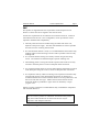
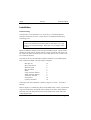
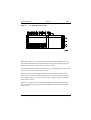
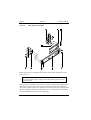
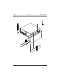
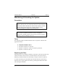
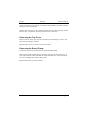
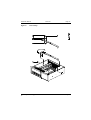
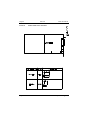
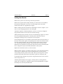
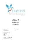
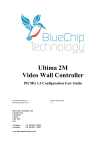
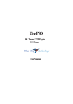
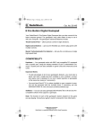
ICON
The Industrial PC
User Manual
2
ICON
User Manual
Document Part N°
Document Reference
Document Issue Level
0127-0198
Icon\...\0127_0198.DOC
1.0
All rights reserved. No part of this publication may be reproduced, stored in any retrieval system, or
transmitted, in any form or by any means, electronic, mechanical, photocopied, recorded or otherwise,
without the prior permission, in writing, from the publisher. For permission in the UK contact Blue Chip
Technology.
Information offered in this manual is correct at the time of printing. Blue Chip Technology accepts no
responsibility for any inaccuracies. This information is subject to change without notice.
All trademarks and registered names acknowledged.
Blue Chip Technology Ltd.,
Chowley Oak, Tattenhall,
Chester, Cheshire,
CH3 9EX
Telephone : 01829 772000 Facsimile : 01829 772001
Amendment History
Issue
Level
1.0
Issue
Date
25/02/98
Author
RT
Amendment Details
First Approved Issue
4
CONTENTS
INTRODUCTION...........................................................................................1
Features .......................................................................................................1
DESCRIPTION...............................................................................................2
Chassis .........................................................................................................2
Rack Mount...............................................................................................2
Desktop.....................................................................................................4
Front panel ..................................................................................................4
Rear Panel ...................................................................................................5
Power Supply & BBU..................................................................................5
TECHNICAL SPECIFICATION ...................................................................5
EMC ............................................................................................................6
INSTALLATION............................................................................................8
WARNING .............................................................................................10
MAINTAINING & EXTENDING THE SYSTEM......................................12
Precautions ................................................................................................13
Tools...........................................................................................................13
Replacing the Filter...................................................................................13
Removing the Top Cover...........................................................................14
Removing the Board Clamp......................................................................14
Adding New Boards ..................................................................................16
Removing an Expansion Board ...............................................................18
Replacing the PSU.....................................................................................18
ICON User Manual
Introduction
Page 1
Introduction
The ICON is a ruggedised PC compatible microcomputer designed for reliable
operation in adverse environments. The unit can take a variety of PCcompatible ISA and PCI cards with both passive and active motherboard. It is
available as a 19" rack mountable unit, and as a desktop unit. Both units use a
common chassis and layout. System controls and disk drives are protected
behind a sealed lockable steel door. The machine is cooled internally by filtered
air which enters through a removable filter at the front panel and exits at the
rear. Access to boards is by a removable top cover. Connections to the boards
are made at the rear of the chassis and behind the front door.
Features
• Robust polished stainless steel chassis using recognised electromagnetic
compatible (EMC) emission and immunity design techniques.
• Front panel with lockable door security for system controls.
• ATX, PICMG & ISA compliant.
• Unique front panel status display allows monitoring of power rails, alarms
and optionally CPU diagnostics.
• Rear panel connector for external processor reset.
• Various switch mode power supply unit
• Optional battery back up for power supply DC outputs.
• Shock and vibration protected drive cage
• Two drive cages allow the choice of either horizontal or vertical mounting to
offer all full length card population or maximum storage capacity.
• Filtered air through two 92 x 25 mm, 12V DC fans mounted behind the
filter panel.
• Quick access to the air filter. The filter is a coated polyester material of 30
PPI porosity having a flammability rating to UL94 Class V0.
• Modular construction allows fan removal/replacement without entering the
chassis.
• Optional card clamp.
• Optional telescopic slide rail fittings.
• Each system is supplied configured to order. The System Release
Documentation details each particular system's configuration.
Blue Chip Technology Ltd.
01270198.doc
Page 1
Page 2
Technical Specification
ICON User Manual
Description
Chassis
The basic chassis is common to both types of assembly (rack mounting and
desktop), and comprises several sub-assemblies:
Chassis body including the cooling fan support brackets
Chassis front panel
Chassis cover
Internal drive cage assembly
Power supply unit and associated battery pack
The common metalwork is of stainless steel construction with riveted fitments.
Removable items are fixed by screws.
Fitted internally are two cooling fans, the chosen passive/active back plane and
drives.
The front panel has two hinged doors. The left hand one has a slotted front to
allow air through to the filter. The right hand door which can be lockable gives
access to the drive bays, the power and reset switches and keyboard connector.
Rack Mount
The rack mounting chassis is made of polished stainless steel and is shown in
Figure 1. It comprises the same chassis as the bench mount, but has mounting
ears. The chassis is completed by a polished stainless steel lid held in place by
eight screws.
The front panel is a 4U high, full 19” racking width panel. The front panel is
slightly higher than the chassis itself in order to allow the use of top cover
screws. The front panel secures the unit to the rack ladder by four fixing
screws. To permit withdrawal from the racking, handles are fitted to the front
panel.
The rack mount unit has tapped holes along each side to facilitate the mounting
of the slide rails.
Page 2
01270198.doc
Blue Chip Technology Ltd.
ICON User Manual
Figure 1
Technical Specification
Page 3
01270198.doc
Page 3
Rack Mount Dimensions
Blue Chip Technology Ltd.
Page 4
Figure 2
Technical Specification
ICON User Manual
Desktop Dimensions
Desktop
The desktop unit is shown in Figure 2. It comprises the same chassis as the rack
unit, but without the mounting ears.
Take care not to insert longer screws than those provided in the side. Overly
long screws may cause internal damage.
Page 4
01270198.doc
Blue Chip Technology Ltd.
ICON User Manual
Technical Specification
Page 5
Front panel
Operator controls and the air filter are located on the front panel behind sealed
doors. The operator controls are behind a (optional) key-lockable door, on the
right hand side. The filter is held in place behind the left hand door. A push to
open/close operation allows access to the filter.
Rear Panel
All electrical connections to the ICON are made at the rear of the unit. Units are
configured individually to requirements. Refer to the System Release
Documentation for details of a particular PC configuration.
To ensure the integrity of the system EMC, it is important that the chassis earth
stud is connected direct to the best available cabinet earth in rack mounted
installations, because of the proximity of other electrical equipment.
Power Supply & BBU
The chassis is can be fitted with a variety of PS/2 or ATX style PSUs. An
optional Battery Backup Unit can also be provided to ensure operational
integrity in mission critical applications.
Some PSUs may have switchable input voltage range. In these cases the flowing
warning should be observed.
WARNING
Selection of the wrong voltage may cause permanent damage to
the unit. Ensure that the switch is correctly set for the installation
supply before connecting to the supply. If the wrong voltage is
applied to the unit the internal fuse may protect the ICON.
However, this cannot be guaranteed. Blue Chip Technology accept
no responsibility for the consequences of operating the unit on the
wrong supply.
Blue Chip Technology Ltd.
01270198.doc
Page 5
Page 6
Technical Specification
ICON User Manual
Technical Specification
Chassis: 19" Rack mountable polished stainless steel chassis
Optional Card restraining system
Shock mounting for drives
Front panel handles
Optional fully extending heavy duty slide rails
High capacity fans
Air filter approved to UL94 V-0
Locking door covering disk drives, power and reset
switch.
Nitrile/PVC seals - Approved to FMVSS302
Temperature:
0-50 °C
Humidity: 0-90 %RH non-condensing
Shock:
(IEC 68-3-37)
Operating
5G 11 mS, ½ sine wave
Non-operating
15G 11 mS, ½ sine wave
Vibration:(IEC 68-2-27)
Operating
5 to 500 Hz, 0.5G
Non-operating
5 to 500 Hz 2.0G
Page 6
Safety:
Designed to meet EN 60950
EMC:
EU Directive 89/336/EC
Emissions EN55022, Class A (1995)
Immunity
EN50082-2 (1995)
01270198.doc
Blue Chip Technology Ltd.
ICON User Manual
Technical Specification
Page 7
EMC
This product as supplied meets the requirements of the European Union
Directive 89/336 EC and is eligible to bear the CE mark.
It meets the requirements for an industrial environment. However, it must be
noted that because the unit is user configurable, certain precautions will be
required to maintain that compatibility.
• The body of the unit must be earthed using the earth stud on the rear,
adjacent to the power supply. The earth lead should be as short as possible
and connect to the incoming cabinet earth.
• If a rack-mounted monitor is used, it is recommended that the monitor body
earthing stud be connected using as short a lead as possible to the PC body
earthing stud.
• It is essential that the housing lid is firmly secured using all the fixing
screws. The lid must be earthed through a separate earthing wire.
• The blanking panels covering the unused expansion slots must be securely
screwed to the back panel to ensure an adequate earth connection.
• Any expansion boards must be correctly fitted and the metal bracket secured
to the back panel using the screw to ensure an adequate earth connection.
• It is imperative that any cables connecting to the expansion boards are fully
screened and connect to the metal bracket and hence are earthed. It is
recommended that woven braid screened cables are used in preference to the
foil screen and drain wire type. Metal connector shells which connect
around the braid are preferable to types which are earthed by a single
“pig-tail” wire.
Failure to comply with these recommendations may invalidate the compliance
with the EMC Directive.
WARNING
This is a Class A product. In a domestic environment this product
may cause radio interference in which case the user may be
required to take adequate measures.
Blue Chip Technology Ltd.
01270198.doc
Page 7
Page 8
Parts List
ICON User Manual
Installation
Rack Mounting
If the ICON is to be installed in a 19" rack unit, it is recommended that
telescopic slide rails are used. A slide rail kit is available from Blue Chip
Technology Ltd.
WARNING
Under no circumstances must the ICON be mounted in a 19” rack
solely by its front panel fixings. Slide rails or a rear support must
be used.
Before installation carefully assess the space available. Figure 1 gives outline
dimensions of the chassis. Ensure there is enough room at the rear of the unit
for cables. DO NOT mount the unit in such a way that air inlet or outlet vents
are covered or blocked.
The slide rail kit will accommodate cabinets with front to rear ladder depths
from 510mm to 690mm. The slide rail kit comprises:
M6 cage nut
M6 x 16 PH screw
M6 brass screw
M6 cup washer
Block
Large extension bracket
Small extension bracket
Telescopic slide rail
Fixing screw
Captive nut/washer
12
4
8
3
4
2
2
2
10
10
Telescopic slide rail installation is shown in Figures 5, 6 and 7. Proceed as
follows :
Refer to Figure 5 to identify the pattern of the ladder holes. Holes A and D hold
cage nuts to which the front panel will eventually be secured. Holes B and C
hold cage nuts and clamp the front end of the fixed section of the slide rails
using tapped blocks.
Page 8
01270198.doc
Blue Chip Technology Ltd.
ICON User Manual
Figure 5
Parts List
Page 9
19” Racking Ladder Holes
Referring to Figure 6, clip cage nuts (A) into front and rear ladder sections in
the positions indicated. Then insert the brass screws (B) fully through the cage
nuts indicated. Loosely attach block (C) to these screws.
Loosely attach slide rail extension bracket (D or E, as appropriate) to outer slide
rail (F) with a screw (G) and captive nut (H).
Insert the slide rail front flange between cage nut and block at cabinet front.
Insert slide rail extension bracket flange between cage nut and block at cabinet
rear. Lightly tighten up the front and rear screws. Tighten slide rail extension
bracket fixing screws.
Remove inner slide rails (I) and (J) by pulling them all the way out until they
lock. Press the spring catch situated on the outside of the middle rail to unlock
inner section.
Blue Chip Technology Ltd.
01270198.doc
Page 9
Page 10
Figure 6
Parts List
ICON User Manual
Slide Rail Sub-Assembly
Referring to Figure 7, attach the inner rails to ICON sides using M4 x 6 pan
head screw (A).
WARNING
Do not use longer screws. Longer screws may damage the electronics
within the unit.
Slide unit on to extended inner sections. Press the spring catches and push unit
forward until catches lock in first position. Press the catches again and slide
unit home. Tighten rear screws. Adjust unit until front panel is central and does
not foul equipment panels above and below. This is best achieved by adjusting
each side and tightening front screws separately.
Page 10
01270198.doc
Blue Chip Technology Ltd.
ICON User Manual
Parts List
Page 11
When the unit is satisfactorily adjusted, secure ICON to the cabinet with screws
(B) and cup washers (C).
Figure 7
Slide Rail Assembly
Blue Chip Technology Ltd.
11
01270198.doc
Page
Page 12
Page 12
Parts List
01270198.doc
ICON User Manual
Blue Chip Technology Ltd.
ICON User Manual
Parts List
Page 13
Maintaining & Extending the System
Precautions
WARNING
Before removing any cover ensure that the unit is both switched off
and that the mains cable has been disconnected. Failure to switch
the unit off will result in the PSU operating from the battery.
Note that dangerous voltages exist within the unit.
WARNING
The electronic assemblies within the unit are susceptible to
electrostatic discharge (ESD). Take anti-static precautions before
handling, otherwise damage will occur.
Tools
The following readily available standard tools are required to maintain and
upgrade the ICON:
•
•
•
•
•
Crosspoint screwdriver size 1
Crosspoint screwdriver size 2
Flat blade screwdriver 5 mm wide
Spanner or nutdriver 5.5 mm AF (nutdriver preferred)
Spanner or nutdriver 8 mm AF
Replacing the Filter
Depending upon environmental conditions, from time to time the inlet filter will
need to be cleaned. The air filter is accessible from the front of the chassis.
Routinely examine the filter for dust build up. It may be cleaned or replaced..
To remove the filter press the middle top of the left hand door and release to
allow the door to open. Remove the filter by pinching the middle of the filter
with forefinger and thumb.
Blue Chip Technology Ltd.
13
01270198.doc
Page
Page 14
Parts List
ICON User Manual
Wash in the filter in warm water to which has been added a low foam domestic
detergent, rinse and drip dry.
Replace filter into the recess in the front panel and close door ensuring that the
fastener slot is horizontal. Push the fastener until it clicks shut.
Removing the Top Cover
Remove the two front cover screws and release the remaining six screws. Lift
the lid off by sliding it forward.
Replacing the unit cover is the reverse of the above.
Removing the Board Clamp
The ICON system can be fitted with an optional board clamp.
Removing the ICON board clamp consists of removing the two screws (C) at
each end. Carefully rotate and slide the clamp assembly out of position taking
care not to damage the boards in the process.
Replacement is the reverse procedure.
Page 14
01270198.doc
Blue Chip Technology Ltd.
ICON User Manual
Figure 8
Page 15
01270198.doc
Page
PCB Clamp
Blue Chip Technology Ltd.
15
Parts List
Page 16
Figure 9
Page 16
Parts List
ICON User Manual
PCB Clamp Screw Selection
01270198.doc
Blue Chip Technology Ltd.
ICON User Manual
Parts List
Page 17
Adding New Boards
Remove the system cover, observing anti-static precautions.
Remove the expansion board clamp assembly. If a new board is to be added to
the system the clamp has to be set up to suit the height of the new board,
because PC boards vary significantly in height.
Before installing the board, measure the PCB height as shown in Figure 9, and
select a screw length appropriate to the card height.
Check the expansion card documentation to ensure it is correctly configured.
Pay particular attention to the selection of the link settings.
Identify the back plane connector slot to be used. Referring to Figure 10, remove
the corresponding blanking plate in the back panel of the chassis (B) by
undoing the retaining screw (C). Keep the screw and panel.
If a full length board is to be installed, locate the board end (nearest the front of
the unit) into the plastic guide corresponding to the chosen slot. Slide the board
down the guide (D) until the edge connect contacts the back plane connector
(A). Press the board firmly into place. Note that the lower end of the metal
bracket has to be pushed into a spring clip just below the level of the back plane.
This is designed to improve the EMC performance of the system.
Replace the end bracket screw (C) removed earlier.
Referring back to Figure 8, assemble an half nut (F) to the selected board clamp
screw (D or E), and insert the screw into clamp bracket (A) in the position
corresponding with the position of the board. Ensure just enough screw thread
protrudes beyond the under side of the bracket to push on a clamp foot (B).
Fit the PCB clamp assembly into position. Align with the holes in the case and
secure using screws (C).
Carefully adjust clamp screw to apply a vertical pressure, ensuring that the
longest face of clamp foot is aligned along the PCB length. Do not over-tighten
the clamp screw, this may bend the PCB.
Blue Chip Technology Ltd.
17
01270198.doc
Page
Page 18
Parts List
ICON User Manual
Finally, tighten half nut to secure clamp screw.
Before replacing the system cover, ensure that there are no clamp screws
protruding above the top edge of the side walls.
Removing an Expansion Board
With the unit switched off and the mains cable disconnected, remove the cover
and the board clamp assembly. Undo the screw securing the board in place.
Carefully remove the board from the connector by gently pulling the board at
each end in a rocking motion (in a plane along its length front to back, not side
to side). Slide the board upward and out of the unit.
Replace the blanking panel and screw ensuring that the end of the panel sits in
the spring at the bottom.
Replace board clamp assembly and cover.
Replacing the PSU
To remove the power supply unit, first ensure that the power supply is switched
off at the front panel. Disconnect the AC supply to the unit.
Remove the top cover as described previously.
Disconnect the DC output leads from the drives and the active/passive back
plane.
With a cross-point screwdriver remove the two screws behind the drive bay
door, holding the mains on/off switch bracket.
Inside the chassis remove the single screw holding the PSU to the side wall. At
the rear of the chassis, remove the four screws holding the body of the PSU in
place, and lift out the PSU.
Replacement is a reversal of the removal process.
Page 18
01270198.doc
Blue Chip Technology Ltd.