1
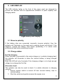
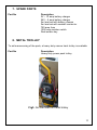
GO-PAK
12V and 24V Models
Extra Heavy Duty Booster Pack
For Professional Operators
USER MANUAL
Powervamp Limited
22 Bridgwater Court, Oldmixon Crescent, Weston-super-Mare
BS24 9AY United Kingdom
Telephone +44 (0) 1934 643000
Fax +44 (0) 1934 642800
Email [email protected]
1
Contents
1. SAFETY INSTRUCTIONS
2. PRODUCT OVERVIEW
3. OPERATING INSTRUCTIONS
4. BATTERY RECHARGING
4.1 Mains charging
4.2 In-vehicle charging
5. LED DISPLAY
5.1 Reverse polarity
5.2 Battery status
6. SPECIFICATIONS
7. SPARE PARTS
8. METAL TROLLEY
Contact details
2
1. SAFETY INSTRUCTIONS
This portable high energy power source uses ultra high discharge sealed lead
acid batteries with characteristics designed to deliver the very high cranking
currents required to start the wide variety of gasoline and diesel engines used
in automobiles, buses, trucks, agricultural vehicles and heavy plant. The
sealed batteries contain no free liquid and require no maintenance. The pack
can be operated in any position
Always observe the following
•
•
•
•
•
•
•
•
•
•
Do not short circuit this equipment – Never attempt to check power by
striking alligator clips together.
Always check polarity when connecting the pack to any battery or
vehicle.
Operators must remove the red isolator key from the key switch when
the unit is not in use.
To maximize performance, ensure all vehicle accessories are
switched off before turning on the red isolator switch.
With diesel engines, wait for pre-heat light on the vehicle to extinguish
before cranking.
Only use battery charger provided with the pack.
NEVER allow the power pack to become fully discharged (battery
“deep discharge” failure can occur) – Not covered by warranty.
ALWAYS secure alligator clips to the vehicle battery BEFORE turning
on the red isolate switch.
NEVER connect or disconnect live alligator clips to any vehicle or
battery. Explosion or engine control unit damage can occur.
This pack is heavy (60lbs), it is recommended to use the side carry
handles provided for two person lifting.
3
2. PRODUCT OVERVIEW
3
8
1
6
2
11
5
4
7
9
10
Fig1. 12V Go-Pak and 2m alligator lead set
1
2
3
4
5
6
Battery LED status display
12V/24V connector
Main handle
Side-handles
AC Input charger socket
Isolator switch
7
8
9
10
11
Red isolator key
750A Protection fuse
Alligator red clip (+)
Alligator black clip (-)
Output lead connector
4
3. OPERATING INSTRUCTIONS
Note: This product is extremely powerful. DO NOT use without reading
and understanding these instructions
1. Ensure that red isolator key is removed from isolator switch.
2. Insert the alligator lead set to the 12V or 24V connector on the front of
the pack (depending upon vehicle voltage and unit model).
3. Connect both the alligator clips to the battery as follows:
Red clip = positive (+) battery terminal
Black clip = negative (-) battery terminal
CAUTION: On 24V vehicles, make sure the alligator clips are
connected to the final output + - battery terminals and NOT across the
+ - series link. Incorrect connection in this instance will result in a dead
short and severe damage to the pack.
If the leads are connected incorrectly, the battery status indicators will
not illuminate and the reverse polarity warning buzzer will sound.
Note: indicators and buzzer will not operate if the vehicle battery is
totally flat or no battery is fitted. In this situation, check carefully that
the leads are connected correctly before turning on the power.
4. Insert red isolator key and turn clockwise to activate pack and
establish power to vehicle. On diesel engines wait for the pre-heaters
on the vehicle to operate.
5. Engage vehicle starter and allow starter to crank engine as normal.
6. Do not crank engine for longer than 10 seconds unless engine is
firing. If engine is not firing or has not started, turn off pack, wait two
minutes for pack to recover then repeat sequence again.
WARNING
Once the vehicle has started, allow engine to stabilize and then switch off
pack. DO NOT leave pack connected to vehicle. Overcharging from the
engine alternator and release of hydrogen gas and possible explosion can
occur.
7. Switch off key switch and remove red isolator key.
8. Disconnect power pack from vehicle battery by removing the negative
clip, followed by the positive clip.
NOTE: Although this unit is fitted with an anti-surge suppressor, it will not
protect the alternator if the vehicle battery is open circuit or no battery is fitted.
Switching off the power pack with the engine still running may cause damage.
If in any doubt, switch off the engine before switching off the power pack.
5
Protection Fuse
The power pack is fitted with a protective output fuse which may blow under
the following circumstances:
- Reverse polarity – if the pack is turned on with the battery clips
reversed.
- Short circuit – if the battery clips are touched together with the pack
turned on or a direct connecting across the series or parallel link is
made in error.
- CAUTION: Over cranking – if the vehicle is continuously cranked for
more than 15 seconds, the high discharge amps can cause excessive
heating of batteries and isolator switch leading to pack failure. In this
event, the safety fuse may not fail since a direct short circuit has not
occurred.
If the fuse should blow, loosen the two bolts and remove the fuse, then
replace with the same value (Part:F750) and re-tighten bolts.
6
4. BATTERY RECHARGING
The power pack is supplied with a special Powervamp two-stage external
charger that is designed to allow the power pack to remain on permanent
charge where the pack is in regular daily use. The unit can also be recharged
using a suitable in-vehicle charging lead. Vehicle voltage must be the same as
the pack.
4.1 Mains charging
1. Ensure isolator switch is turned off and red key removed.
2. Ensure mains supply is switched off then connect charger lead to
power pack.
3. Switch on mains supply to charger and place charger switch to the ON
position.
• Charge status indicator on charger should illuminate red (see
charger label)
• Charge status indicator on the pack should illuminate green
(see section 5.2)
4. When charging is complete, indicator on charger will change from red
to green. Approximate time from discharge to full battery recovery can
be up to 12 hours.
4.2 In-vehicle charging
1. Ensure isolator is turned off and red key removed.
2. With the vehicle engine switched off, connect in-vehicle charged lead
to power pack and connect other end to vehicle 12V or 24V DC
accessory socket – depending upon pack type and vehicle voltage.
3. Start engine and pack will begin charging from the vehicle alternator.
• Charge status indicator on pack should illuminate green (see
section 5.2)
Pack recovery from heavy use is dependent upon the engine running time and
alternator output voltage.
CAUTION:
If the vehicle DC socket is not ignition controlled, it is essential that the charge
lead is removed from the socket whenever the vehicle is left unattended, to
avoid possible battery pack discharge.
7
5. LED DISPLAY
The LED indicator lights on the front of the power pack are designed to
provide the operator with an approximate indication of pack capacity and
charging status.
Fig2. Battery LED Display
5.1 Reverse polarity
If the battery clips are connected incorrectly (reverse polarity), then the
indicator will illuminate on the pack and a warning buzzer will sound. If this
happens, reverse the battery clips before proceeding. If in doubt, seek
professional help before switching on pack.
5.2 Charge status
Go-Pak charging
When the pack is connected to the mains charger or in-vehicle charging lead,
this indicator will illuminate to show the internal battery is being charged
correctly.
Note: the LED will only illuminate if the charging voltage is at a high enough
voltage to re-charge the Go-Pak.
Alternator check
This indicator can also be used to check if a vehicle alternator is charging
correctly.
1. Ensure isolator switch is turned off then connect battery clips to
vehicle battery.
2. Start the vehicle and gently increase the engine revs.
8
3. The charge status LED will illuminate when the alternator output
voltage is sufficient to recharge the battery.
5.3 Battery status
LED display
With the isolator switch turned on, these indicators show the charge condition
of the power pack battery. When only the ‘low’ indicator is illuminated, the
pack must be recharged.
Vehicle battery
With the isolator switch turned off and the leads connected to the vehicle
battery, the battery status indicators will show the approximate charge
condition of the vehicle battery.
9
6. SPECIFICATIONS
Volts (nominal)
Amp/hour capacity
Battery type
Rated input voltage
Safety fuse (amps)
Peak amps
Cranking amps
Cold cranking amps
Battery shelf life
Output cables (length)
Output cables (core dia)
Parallel and series yokes
Alligator clips, cast brass,
braided
Reverse polarity warning
Capacity status LEDs
Safety isolator (key switch)
12V Gasoline engines
12V Diesel engines
24V Diesel engines
Charge time from flat
Charger specification
Weight
12V Go-Pak
24V Go-Pak
12VDC
24VDC
52
26
2 x 26Ah in parallel
2 x 26Ah in series
230V/50Hz AC
500
750
4800
2400
2220
1110
912
456
24 months (from fully charged)
6ft (2m)
0 gauge (50mm sq)
No
1000 amps
Fitted
Fitted
1000amps
Up to 7 litres
Up to 3.5 litres
Up to 14 litres
5.5 hours to 95%
10 amp, 12v, 2-stage
6 amp, 24V, 2-stage
59lbs (27kgs)
Dual outputs Go-Pak (12V and 24V) are also available.
10
7. SPARE PARTS
Part No
Description
2V – 10 amp battery charger
24V – 6 amp battery charger
2m lead set with battery clamps
2m lead set with cowbell connector
750 amp fuse
1000 amp isolator switch
Red isolator key
8. METAL TROLLEY
To aid manoeuvring of the pack, a heavy duty narrow track trolley is available
Part No
Description
Heavy duty power pack trolley
Fig3. Go-Pak fitted on metal trolley
11
Contact details
UK:
Powervamp Ltd
22 Bridgwater Court
Oldmixon Crescent
Weston-super-Mare
BS24 9AY
United Kingdom
Telephone: +44 (0) 1934 643000
Fax: +44 (0) 1934 642800
Email: [email protected]
USA:
Powervamp USA
Brian Clear
6426 Woodbury Road
Boca Raton
FL33433
USA
Telephone: +1 561 542 8867
Email: [email protected]
12