1
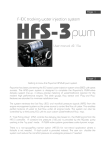
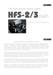
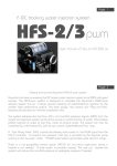
RX7 IDC tracking water injection system
osa
User manual
with IDC Summer wiring diagram
Page 2
GETTING TO KNOW THE AQUAMIST HFS-6 osa
Aquamist has been pioneering the IDC based water injection system since 2003 with
great success. The HFS-6 now offers “user re-scaling” and “manifold pressure compensation” adjustment. This new capability sets a new level to the concept of WAI system to
date. .
The concept behind the HF5-6 osa (open source architecture) design is somewhat unusual
in many ways in the key-tapping digital age. It goes one step beyond the current cell by
cell on-screen programming via a lap top. The only tool needed is a small screw driver. User
can define the entire flow curve by manipulating five onboard trimmer potentiometers. Each
trimmer is pre-programmed with a mathematical formula to simplify the flow mapping work.
The wiring task has also been revamped to cut installation time. Three dedicated colour
coded, pre-terminated wiring harnesses are allocated for each area of the car, covering the
engine bay, ECU and water tank/pump in the trunk. Continuing the same tradition of constant
water pressure and fluid flow is controlled by newly designed inline high speed valve. This
new valve is necessary to handle the new line pressure of 160psi, risen from the previous
pressure of 125psi.
Page 3
Contents:
System Check
Page
4
5
Checking the contents of the box
Getting started on the installation
6
7
8-9
Installation for long-term reliability
Generic wiring diagram
Choosing jet size
10
11-12
HFS-6 pin-out function directory
Quick Start
13-14
Advanced delivery management
15-16
Dash Gauge functions
17-19
Fail-safe configurations
20-21
Advance system configuration
22-23
Wiring details Guarantee and Warranty
Installation
System testing
Gauge
Dash gauge
Fail-safe
Advanced
Appendix
Checking the contents of the box carefully
This is a “must do” immediately
after unpacking ....
Water pump
Unpack the corrugated sheet carefully. The pump
should be labelled with the original custom Aquatec/
Aquamist logo. Model number: 58832P0D-B664AM
The white box
♦
♦
♦
♦
♦
♦
♦
♦
♦
♦
6M of 6mm OD nylon hose (806-261)
2M of 4mm OD nylon hose (806-266)
15A Fused water pump harness with 40A relay
75mm stainless hose clip and support bracket
HFS-6 Flow Control Module with 2.5M of red
capped RJ45 connector harness.
0.8 mm water jet (806-323) in plastic bag
0.9 mm water jet (806-324) in plastic bag
1.0 mm water jet (806-325) in plastic bag
1x 4mm Y-piece (806-362) in plastic bag
2x M8 x 1/8 NPT jet adapter with plug (806-357N)
Page 4
♦ A set of three restrictors with threaded tool
♦ 1x water tank adapter 1/8 BSP (806-270) + 6mm
qck-fit elbow (806-376)
♦ 100 micron inline water filter (806-257)
♦ 4x M5x 40mm, nuts, washers and fasteners for
pump
♦ 1x M6 grounding stud with washed and nuts
and 6mm eyelet for pump ground
♦ 5-port brass manifold with 3/8BSP adapter. 3x
blanking plugs, 1x 3/8 BSP-M to 1/8BSP-F adaptor 2x 6mm 1/8BSP-M elbow.
♦ 1x 22cc surge arrestor/accumulator (806-409)
♦ Water pump harness. 6M of #12 AWG cable
and 6M of multicore cable with blue RJ45.
♦ HFS-6 controller box
♦ 1x water level switch with connector (806-280c)
♦ 1x DDS3 Dash Gauge with 1.5 M x 8-way cable
♦ 2M of multicore with yellow capped RJ45 for
.
ECU interface, fail-safe and Map switching.
♦ User manual
Note: Please contact your supplier immediately should you discover any missing parts.
Page 5
Getting started on installation
Before installation guidelines
♦ The pump and water tank are designed to be
fitted in the trunk. Install the water pump and
inline filter below the water tank.
♦ Ensure all fittings are tightened and leak proof
before filling up with methanol, test it with
water first. If high concentration of methanol is
used, please vent the tank’s breather hole externally. Methanol is poisonous at high concentrations.
40A
RELAY
WATER TANK
IN TRUNK
BATTERY+
Installation for long-term reliability
This is the most important section of the HFS-6
chapter. Please do not skip reading this part.
52mm Dash Gauge:
Location is not too critical as long as it is in view of
the driver. There aren’t too many pitfall on this.
HFS-6 controller box:
Please locate the box in a dry location in the pass
compartment. Near a glove box is whats been
found to be best. Please route the wiring and secure
loosely so that tuning and diagnostics can be made
without too much dis assembly in order to gain easy
access = its been found by professional installers
and advanced users that it would be nice to hold the
box in the hand while sitting in the front passenger
seat when tuning or diagnosing.
Flow Control Module (FCM):
The location of this module is most critical to overall
system reliability. It is designed to be installed in the
engine compartment.
This module must be installed in a cool and dry area,
well away from the heat source. Bulkhead/fire wall
is not a good location as most heat is flowing towards it during driving. Avoid location near any electromagnetic components such as the ignition coil,
solenoid valves and electronic motors. It is very
important that the hose is cut cleanly with a razor
DDP5800
THIS PUMP IS FACTORY SET TO 160PS. DO NOT
ATTEMPT TO INCREASE THE BY-PASS VALVE
PRESSURE OR THE LIFE EXPECTANCYWILLBE
GREATLY REDUCED. IT IS NOT RECOMMENDED
TO RUN BEYOND 50% METHANOL BECAUSE OF
FLAMMABILITY AND VAPOUR INHALATION CAN
BE HAZARDOUS TO YOUR HEALTH.
160 PSI BYPASS PUMP
MADE IN USA
BY
AQUATEC
806-409
Assembling the pump in steps
♦ Gently assemble the two 3/8 BSP adapters into
the pump without crossing the threads. The
female one goes into the inlet of the pump.
Flow direction is moulded onto the plastic
pump head. Ensure o-ring is properly seated.
♦ Ensure the accumulator lies horizontally after
final tightening (relative to the pump length).
♦ Assemble the accumulator supporting bracket
with the metal band supplied.
♦ Assemble the rest of the 1/8 BSP elbow fittings
and blanking plugs. Ensure all o-ring type fittings are not overly tightened.
♦ Mark (smear dye on to the pump’s rubber feet)
and drill four holes for the pump.
Water tank components
♦ Ensure the outlet is facing the rear or the side of
the tank. Drill/bore a burr-free 23mm hole. Clear up
all the burred edges and wash the tank thoroughly.
No debris or plastic shaving should remain in the
delivery system. 1-2 inch from the bottom of the
tank is ideal. Don’t over tighten.
♦ Same hole size for the water level sensor. IF using
a washer tank for supply, do not locate the Aquamist float sensor near the stock washer pump..
The float should swing upwards.
♦ A tall and slim water tank is ideal for this type of
application. This minimises delivery surge problems at low water level.
Page 6
blade to retain the “roundness”. Side cutter produces a semi-round hose end, major leak will result
sooner or later. It is also vital that the hose must be
cut be perpendicularly relative to this length. This is
because the compression has a short hosetail, an
accurate cut will allow maximum grip on the walls
of the hose.
The ground tag must make a good electrical contact
to the chassis ground. Smear some grease on the
junction to protect it from moisture.
8-feet of two-core cable from the FCM is intended
for fail-safe purposes. It activates a low-power 3way solenoid valve to by-pass boost pressure to the
wastegate. In the event of a fail-safe activation, it
will lower the boost down to the mechanical failsafe setting. This option is normally intended for
use with a manual boost controller and some stepper-motor based electronics boost controller.
The Tank level sensor:
Check there is ample room of the sensor arm to
swing before drilling. If stock washer tank is going
to be used, do not mount float near stock washer
pump. The motor magnet will affect the sensor to
read properly. The sensor can be installed 3/4 way
down the tank, Preferably at the rear facing wall of
the tank. A 23mm burr-free hole must be used to
ensure good seal. Never over tighten or the seal will
split, just tight enough to prevent leakage, no more.
Generic wiring diagram
Page 7
(go to page 22 for RX7 specific diagram)
FLOW CONTROL MODULE
Aquamist
100
200
300
IGNITION SWITCH (INJECTOR +)
FUEL INJECTOR (-)
MAP SENSOR (0-5V)
400 ml/m
FLOW
ENGINE CONTROLLER
W. INJECTION
WATER LEVEL
SC
WL
WH
M a d e in ng la n d
E
SWITCHED
12V
+
HFS-6 osa
Flow Control Module
OPTIONAL
WASTEGATE
BY-PASS
VALVE
WATER PUMP IN TRUNK
FUTURE
PRODUCT
INTERFACE
PORT
HEAD
LAMP
SWITCH
40A
RELAY
DDP5800
THIS PUMP IS FACTORY SET TO 160PS. DO NOT
ATTEMPT TO INCREASE THE BY-PASS VALVE
PRESSURE OR THE LIFE EXPECTANCYWILLBE
GREATLY REDUCED. IT IS NOT RECOMMENDED
TO RUN BEYOND 50% METHANOL BECAUSE OF
FLAMMABILITY AND VAPOUR INHALATION CAN
BE HAZARDOUS TO YOUR HEALTH.
DASH
GAUGE
POWER
INPUT
K1C12H
ENGINE
BAY
5A FUSE
TRUNK
AREA
USER
PORT
K1C12H
160 PSI BYPASS PUMP
BATTERY+
WATER TANK
IN TRUNK
MADE IN USA
BY
AQUATEC
COIL 12VDC
3A 30VDC/125VAC
806-409
COIL 12VDC
3A 30VDC/125VAC
TO
ECU
47OHM 7W
9716785
Choosing jet sizes
Pressure vs Flow
600
Page 8
This is a general guide only:
- 100% water: run 10-15% water/fuel ratio.
- 50:50 methanol/water, run 15-20% to fuel.
- 100% methanol, run 20-25% to fuel
550
500
1.0mm
450
0.9mm
Flow cc/min
400
0.8mm
0.7mm
300
0.6mm
250
0.5mm
200
0.4mm
150
0.3mm
100
60
70
80
90
100 110 120 130 140 150 160 170
Pressure (psi)
Pick the nearest jet/jets size to match the flow.
Don’t forget to subtract the boost pressure from
the line pressure of 160psi. For example, if you are
boosting 25psi, you should select the jet flow at
135 psi.
Once the jet/jets and flow are determined, insert
the nearest HSV restrictor to regulate the fluid flow
so the delivery will be linear to the duty cycle.
JET
0.3
0.4
0.5
0.6
0.7
0.8
0.9
1.0
60
108
144
194
215
251
287
323
359
70
116
155
207
233
271
310
349
388
80
124
166
220
249
290
332
373
414
90
132
176
232
264
308
352
396
440
100
139
185
243
278
324
371
417
463
110
146
194
254
292
340
389
437
486
120
152
203
264
305
355
406
457
508
130
158
211
274
317
370
423
475
528
140
164
219
284
329
384
439
493
548
150
170
227
293
340
397
454
511
567
160
176
234
302
352
410
469
527
586
170 PSI
181
242
179
362
423
483
544
604
FLOW RATE: CC/MIN
350
Choosing the jet by calculation:
First work out the total fuel flow by adding up the
capacity of the fuel injectors. Multiply the result by
the preferred % recommended above.
Page 9
The HFS-6 is supplied with a set of high-flow
water jets, sized at 0.8, 0.9 and 1.0mm (see
chart for flow rate). A Y-piece is supplied with
the kit for twin jet applications. There are two
nickel plated brass jet adapters (1/8 NPT). The
tapping hole should be 11/32“ or 8.8mm. Do
not over tap. Clean the mating part with alcohol first, Trial fit before loctiting into position.
Three restrictors are supplied for duty cycle/
flow matching should good linearity be required. For flow greater than 1100cc/min you
can omit it. It should be fitted inside the inlet
port fitting of the Flow Control Module (FCM).
Applications involving methanol mix beyond 50%:
Great care and attention must be taken to ensure the fluid
tank is capable of handling methanol and is designed for
this type of application. These tanks are normally termed as
a Fuel cell and are available from most reputable racing
parts suppliers. Anti-surge foam should be used for circuit
racing. Follow the maker’s guidelines carefully.
The breather hole must be vented externally with a suitable
hose. All fluid delivery hoses and fittings must be free of
all leaks. Ensure the area is well ventilated and isolated
from the driver’s compartment. Take whatever measures
to avoid any methanol fumes building up in trunk area.
Methanol is highly flammable. The main delivery hose to
the engine bay should be routed underneath the car. Ensure it is securely clipped and fastened. Avoid kinks, close
proximity of moving parts and heat producing components.
Please treat this recommendation seriously. If in doubt,
ask advice from a professional person familiar with this kind
of application. DO NOT take any undue risks. It is recommended that a suitable fire extinguisher is placed within
easy reach of the driver. All electrical connections must be
properly tightened to avoid spark production.
FLOW
Remove the inlet fitting first from the FCM.
Use the threaded insertion tool to push the
restrictor in position, Apply a smear of grease
to avoid damaging the o-ring.
0.5mm restrictor .................... 0 - 380cc/min
0.7mm restrictor .................... 0 - 680cc/min
0.9mm restrictor .................. 0 - 1080cc/min
Warning: Prolonged use of 100% methanol may cause
premature pump failure and may not be covered under
warranty.
HFS-6 function directory
1
DASH
GAUGE
3
4
5
6
ENGINE
BAY
TO
ECU
TRUNK
AREA
USER
PORT
2
POWER
INPUT
K1C12H
10
5A FUSE
Page 10
COIL 12VDC
3A 30VDC/125VAC
K1C12H
COIL 12VDC
3A 30VDC/125VAC
47OHM 7W
8
7
9716785
9
1.
2.
3.
4.
5.
DASH GAUGE (P.15)
12V, HEAD LIGHT SWITCH and GROUND (P.7)
FLOW CONTROL MODULE in ENGINE BAY (P.7)
ENGINE MANAGEMENT and FAIL-SAFE (P.18)
WATER TANK and PUMP in TRUNK AREA (P.7)
6. FUTURE PRODUCT INTERFACE (P.7)
7. DUMMY LOAD RESISTOR for ANTI-CEL (P.18)
8. SYSTEM CONFIGURATION BY USER (P.13-14)
9. FLOW and FAILSAFE POTENTIOMETERS (P13-14)
10. 5A 20mm x 5mm FUSE LINK
Quick Start
Mechanical work (checklist):
Only after testing with distilled water should
methanol be used. BEFORE hooking up line to
the jet the system should be manually ativated
to flush any possibly dirt/disturbis from the lines.
Wiring work (checklist):
The HFS-6 is pre-configured from factory, just
requires the following connections to get to
work.
1. 4-way Power-in connector:
- Red ................ Switched 12V (IGN SW#2)
- Black ............... Chassis ground
- White .............. Chassis ground
- Purple .............. Head lamp switch (optional)
2. Signal to the yellow RJ45 connector:
- Red ................. Ignition switched 12V
- Green ............. Fuel injector (-) pin
- Blue ..................MAP sensor (optional)
Power-up procedure:
Please follow this procedure “strictly” or permanent damage to the system may result.
Do not skip any steps please....
1. Ignition key on the “OFF” or “0” position:
Page 11
- Dash Gauge is plugged in and switched on.
- All the RJ45 plugged are colour matched.
- 4-way plug is engaged into the socket.
- No leds should be lit anywhere.
2. Ignition key on the “ACC” or “#1” position:
Absolutely no change, same as the above conditions.
3. Ignition key on the “pre-cranking” or “#2” position:
- Do not crank. Observe the gauge and controller leds
- Yellow led on the gauge will stay lit for 5-10s before
the rest of the gauge lights up.
- “S” and “W.INJ” led should be lit on the gauge.
- All the green leds on the HFS-6 controller should be
lit with the exception of the green connector.
3. Start the engine and let it idle for a minute or so:
- The green led on the controller should flicker
- The yellow led on the “green” and “yellow” RJ Connector socket should flicker.
- Flicker should speed up with engine speed.
- If the system behaves as stated above, you have
successfully wired up the HFS-6!
The next stage will be testing the system manually by
using the jumpers links on the controller board. You
will need a small 3/32“slotted screw driver. .
Quick Start - Manual testing.
Page 12
Testing the controller functions:
1. Gauge Bargraph test:
Taking the parked “PRK” link
and place it on the “CAL slot”,
MPS IDC PRK CAL TST INJ
you should see 4-5 bars lights
up. Twiddle the “SC” trimmer on the gauge will
yield more or less bars. Clockwise to reduce bars.
Reinstate the “SC” back to 12 o’clock. Make sure
“IDC” is selected.
3. Testing the IDC detection function:
2. Simulating 100% injection test:
Remove the link and put it on the “TST” slot momentarily and observe:
- Amber led on the controller board will light up.
- Red led on the controller board also lights up.
- The yellow should light up except for the blue RJ
connector,
- The water pump will start.
- There should be full spray on the jet instantly
unless the system is not fully primed. Allow a few
seconds for the water to reach the jet. For longer
hose run installations, remove the jet first to allow
faster priming.
- Remove the link and put it back to the “PRK”
position before you empty the water tank. If all is
well, move to the next test stage.
This test confirms the system is detecting the IDC
signal correctly. Set the “THRES-ADJ” trimmed to
minimum (full counter-clockwise). At this setting
(12% IDC), the system should trigger with a quick
blip of the throttle (provided you don’t use very
large fuel injectors). Keep the trimmer in the same
position.
F-IDC
THRES
THRES IDC
ADJ TRIM
>95% DC
IDC BOOST FLSF
GAIN COMP SENS
FLSF
RST
DIM
ADJ
4. Take the car for a test drive:
Eyes fixed on the road and water jet (on screen),
find a stretch of road where you can use full throttle. Do a few quick burst of full throttle runs and see
if the spray is progressive with each acceleration
run. The volume seen at the spray should coincide
with the bargraph readings on the dash gauge.
This concludes the test session of the HFS-6.
Advanced flow management trim
1. “THRES ADJ” (far left):
This sets the triggering point of system based on
the fuel injector IDC%. Adjustment range is between 12% to 72%. Mid-point is 42% (12 o’clock)
2. “IDC TRIM” trimmer:
At mid-point, the water flow matches the fuel
IDC% exactly. For example, if the triggering point
is set to 50% of the Fuel IDC, the DC to the flow
valve will also be at 50%.
WATER FLOW
The trimmer can offset the F-IDC to +/- 20%. This
means that one can deIDC TRIM
crease or increase the
water flow relative to the
+20%
fuel flow. This is useful
for trimming water in different ambient tempera+20%
ture and compensating
FUEL FLOW
for methanol/water ratio
changes.
3. “IDC GAIN” trimmer:
As the previous trimmer does not allow top-end flow
increase or decrease when the starting point of the
DC% is altered. This potentiIDC GAIN
ometer is designed to ad+50%
dress this section of the flow
curve.
-50%
WATER FLOW
The HFS-6 is designed to allow the user to manipulate the two main signals received from the
fuel injector and the MAP sensor. This is achieved
with four trimmer pots. Tweaking of these are not
mandatory for initial system testing after a fresh
install.
Page 13
This allows the user to decrease or increase the water
FUEL FLOW
flow relative to the fuel flow.
This is useful for those who install very large fuel
injectors and never use up the full DC.
4. “BOOST COMP” trimmer:
Since the HFS-6 does not reference the system pressure against the manifold pressure changes. This
inevitably decreases the water flow during boost
periods. This trimmer compensates this shortfall.
0-5V pressure signal is read from the ECU. At Mid
point (2.5V), the system will start to add DC (duty
cycle) to water flow curve as soon as the manifold
pressure signal exceeds 2.5V. The compensation
factor is 4% per volt above the trimmer setting. If
more boost compensated flow is required, just lower
the trimmer setting. A excel based tool is available
for download to help visualising the trimmers.
http://www.aquamist.co.uk/HFS6/DUD1.xls
More advanced flow management trim-continued
Page 14
LEDs to assist visualising the flow curve:
F-IDC
THRES
THRES IDC
ADJ TRIM
FLSF RST (Fail-Safe Reset Timer)
>95% DC
IDC BOOST FLSF
GAIN COMP SENS
FLSF
RST
DIM
ADJ
Green led (F-IDC):
Monitors the incoming Fuel injector signal - flicker
in time with the engine speed, glows brighter with
increase of duty cycle %.
Amber led (THRES):
When the Fuel injector duty reaches the threshold
setting of the trimmer, the led lights up solid.
Red led (>95% DC):
When the flow control valve reaches above 95% of
it rated flow, this led will lit up.
FAIL-SAFE trimmers explained:
5th and 6th potentiometer from the left allows the
user to trim the fail-safe parameters.
FLSF SENS (Fail-Safe Sensitivity):
The “grace” periods before triggering is set to 0.3s
from the factory, User can alter these values to suit
their driving styles.
The failsafe automatically reset in 3 seconds (default)
after activation. In some circumstances as in rally cars,
user requires a faster reset so aggressive map or high
boost is restored almost instantly.
Bigger turbo takes time to spool down especially
when a blow-off valve is installed. This calls for a long
reset time otherwise the boost can never drop down
to the wastegate setting.
This trimmer allows the reset period be adjusted between 1s to 5s.
Automatic Gauge brightness control:
This trimmer works in conjunction with the head lamp
switch. When it see a 12V signal. the trimmer becomes active. This coincides with night drive conditions. The high-intensity led used on the dash gauge is
too bright for night motoring. So wiring in the “purple
wire” from the 4-way power plug to the head lamp
switch is essential.
Do not wire it to the car’s interior dimming circuit or
unexpected results may occur.
Dash Gauge Functions
1
4. Water Level led (yellow)
(This LED has three functions)
a. During “power on delay” period:
This LED will activate for approximate for 10
seconds during the system-on delay before the
main system turns on.
6
7
2
3
b. During normal operation period:
- This LED is on during the fail-safe activation
- Water level low (intermittent flashes)
8
4
c. Led lit after the gauge is switched off:
- If the water level sensor is activated for over
20 seconds.
- fail-safe disabled by DHB (p21.6).
9
5
10
1. 8-element Bargraph Display (80-1800ml/min)
Each segment is equivalent to a percentage of the total
flow of the sensor scaled by the SC potentiometer.
2. “S” indicates the presence of sensor.
The letter “S” (sensor) must be lit after power up and
stay on to show the sensor is functioning correctly.
3. Water injection system ON led
This led comes on the when the system is switched on
and in readiness to inject. .
5. SC (Sensor Calibration)
20-stepped potentiometer allow user to scale
the flow sensor to give an ideal visual indication
of a given flow rate. Ideally set the led to display 5-6 bars at full flow.
6. Backlit flow legend
Legend displays % of full scale of 8-bars
7. “B” Boost Enabled led
When the flow falls inside the fail-safe window
after system trigger, this “B” led will activated.
Useful indicator of the WL and WH setting.
Dash Gauge Functions cont.
8. Water injection enable button
Due to extra power level achieved under WI, user
may want to reduce the power to the wheels in less
than ideal driving conditions. Disabling the WI will
reduce boost to wastegate bleed valve setting (if
fitted) as well as switching to a less aggressive MAP
on custom engine management.
9. Over-range setting potentiometer (WH)
It is just as important to monitor over-range conditions as well as under-range flow conditions. If a leak
develops close to the water jet and starves the
engine of the water, the user must know this condition. A 20-stepped potentiometer allows accurate
and repeatable adjustment range.
10. Under-range setting potentiometer (WL)
This setting can indicate partial blockage and trapped
air inside a delivery hose. Again 20-stepped potentiometer is employed. Each click represents a fixed
portion of the window
width of 8-bars.
failsafe window width
coverage (20-clicks)
WL covers the lower 4
bars and the WH covers the upper 4 bars.
Figure on the right illustrates the span of
the coverage. Setting
is very simple once SC
WL
WH
is calibrated.
Page 15
Page 16
NOTE:
In order to make the fail-safe adjustment easier, it is
recommended to set the bargraph to display 5-6
bars at maximum flow. This way, the fail-safe window can span from the centre outwards.
If the WL and WH is set at 12 O’clock, the fail-safe
window is approximately spanned between 2-7
bars. A good starting point.
Minor trimming for the WL is necessary if the water
injection trigger point is set to commence earlier.
The gauge will display the activation of the “failsafe” with two leds:
1. “B” led (right of the bargraph) will not active if the
flow is outside the fail-safe window during injection
period.
2. The “yellow” led (water level) will activate if the
flow is outside the fail-safe window during injection.
As soon as the “fail-safe ” is tripped, there will be a
3 second reset period before it resets. If the fail-safe
drops boost, user can modify this reset timer. See
fail-safe trimmers on page 14.
When gauge is off, expect low boost and safe map
unless the board is re- configured. (page 21.B).
Setting up the fail-safe
This final stage should be quick simple and
effective, please read it before proceeding.
It will save you time in the long run.
If fluid flow falls inside the fail-safe detection window after triggering, no action will be taken. So
setting up the width of the window to accommodate the full fluid flow is vital.
Setting up the fail-safe should only be done after the
car has been tuned or the jet/jets sizes are finalised.
Recommended steps to set up the fail-safe
1. Adjust the “SC” to display 5-6 bars at full power.
2. Make a mental note of the number of displayed
bars during spool up. Made easier at higher gears.
3. Set the WL to match the number of spool-up bars.
It is recommended to allow 2-3 clicks below that
point to avoid false triggering. Full span of WL is
20 clicks, covering from 0 bar to 4 bars.
Page 17
What steps to take after the failsafe trigger
The most common way to minimise engine damage
in the absence of injector is to reducing the boost
pressure.
1. For engines with electronic boost control valve:
The yellow harness contains a set of relay contacts
that goes open circuit when the fail-safe is triggered.
See page 18.2 and 19 for more details.
2. For engines with MBC (manual boost controller):
There is a dedicate channel for control a 3-port solenoid valve to by-pass the MBC. Essentially reducing
full turbo boost to the wastegate. See page 19 for
more details.
4. Same procedure to set up the WH, allowing
2-3 clicks above 6 bars. Full span of WH is 20
clicks covering 4-8 bars.
3. For engine with map switching capabilities:
The pink wire on the yellow connect has a dedicate
output to perform such a task. This pin can be user
configured match the signal requirement of the
“third party” ECU to switch map. See page 18-1 for
more details. This pin is factory configured to give a
5V for “OK” and “0v” is “flow fault”
This completes the fail-safe setup ...
Maximum current of this output is 5mA.
Setting up the alternative Fail-safe Channels
1. The Map Switching Channel:
The pink wire from the yellow RJ45 connector
is dedicated for the use of MAP Switching
when an ECU is equipped with this input. This
wire is factory configure to send out a voltage
of 4.7 VDC voltage under a “no fault ” condition, from idle to full boost. This voltage will
switch to 0v upon a fail-safe activation or
the gauge is switched off.
PINK
Other voltages such as 0v or 7.5V can be user
configured - see p.21 for more details. This is
by far the most effective method to save your
engine from lack of water injection.
2. Change-over relay contacts:
The HFS-6 has an onboard relay to supply a set of
voltage-free, change-over contacts for the sole use of
fail-safe activation. It can be used to perform various
tasks to save your engine. The contacts are rated up
to 1 amp.
Colour code for relay (normal operation):
- White ....................................... Common contact
- Black ............................. Normally closed contact
- Brown .......................... Normally opened contact
(state changes upon fail-safe activation or sys off)
Example 1 (most common):
Disabling the OE boost control valve. “Cut
and splice” the boost control circuit. “ECU
side” to White. “BCV side” to Brown.
Need to link the “Anti-CEL” option on
page 10.7. Place the jumper link to “DRON” (Dummy load resistor). This is only
necessary if you want to avoid the onset of
CEL during fail-safe activation.
BLACK (N/C)
WHITE (COM)
BROWN (N/O)
Alternative to the previous fail-safe configuration,
using a third party “by-pass valve” to reduce boost via
the FCM (Flow Control Module). There are two more
fail-safe channels available from the “Yellow” RJ45
connector harness.
Page 18
Example 2:
Disabling the third party electronic boost
control system. “Cut and splice” the
pulsed wire to the BCV, “Controller”
side to White and “BCV” side to Brown.
It is not necessary to enable the
“Dummy load resistor” to avoid a “CEL”.
This option will not work with EBC (Electronic Boost controller) utilising a stepper
motor to control boost. HKS-EVC is such an example. Use the MAC valve option on page 17.
Fail-safe wiring to other boost controllers
Upon detection of water flow fault, the HFS-6 can
reduce the boost pressure of a MBC to wastegate
setting. There is “sealed end” 2-core cable attached
to the FCM (Flow Control Module) for this purpose.
If you intend to use this fail-safe channel,
The HFS-6 does not include this valve, You need to
order one from any distributor of MAC valve USA.
Figure below shows two common type of MBC (manual boost controller) used on most turbo cars.
Type 1: pressure from the turbo to the wastegate is
vented to the atmosphere via a restrictor and a vent.
Boost increase is proportional to the amount vented.
Page 19
Type 2: Boost increase is proportional to the
spring pressure of the MBC.
When the solenoid valve is energised, pressure
from the turbo is diverted to the wastegate directly. When MBC is by-passed, the boost pressure will drop down to wastegate setting.
NOTE:
The same MAC valve can be used to reduce boost
on any Electronic Boost control valve system. Use
the same hose configuration as the “TYPE 1”,
with Port 2 blocked-off. See figure below.
MAC valve (36A-AAA-JDBA-1BA) www.macvalves.com
3-WAY
SOLENOID
VALVE
N/C
2
N/O=3
Flow Control Module
NC=1
NO
HFS-6 osa
COM=2
COM=2
NO=3
Advance system configuration (solder link)
2
3
4
CL P
1
5
6
7
Page 20
8
M-SW
COMP
I P
MAPS
I
PWM
WL S
DHB
HFS6
OPEN SOURCE ARCHITECTURE
PCB SETTINGS
PWM IN POLARITY:
M-SW CLAMP:
MAP/IDC COMP:
M-SW POLARITY:
WLS/FAILSAFE:
MAP SENSOR:
DISABLE H.BOOST:
FACTORY
USER
4.7V
PRES
+
ENABLED
EXT
ENABLED
HFS6-v1
(Links are factory preset - no need to alter the setting unless customising)
X
Advanced system configuration (solder link)
The HFS-6 is pre-configured at the factory for general applications. If the user wishes to change the
original setting, this is the section to explain it all.
You will require a small tipped soldering iron and a
small pointed tool. As seen from the PCB figure on
the left. All the user configurable links are marked
with numbered circles.
Some pads are pre-linked from factory. If you need
to change those, pick off the thin track (pointed tool)
and solder link the alternative solder pads.
1: FSI system compensation link (default=off)
Reserved for factory/FSI developer usages only.
2: PWM MODE polarity (default=negative switched)
To change the PWM detection polarity to positive,
pick off the thin track and solder-link the “+” pad to
the long pad.
Page 21
5: M-SW polarity (default= positive until failure)
The factory default output is preset to give a 0V
output upon a fail-safe activation. Otherwise the
output will stay at ~4.7V.
6: DHB - Disable High Boost (default=off)
Pick off the thin circuit track if you want to retain high
boost or “Aggressive MAP” after the system is
switched off at the gauge. Ensure you have race fuel
in your tank. Yellow led will stay on as a reminded
when gauge is switched off.
7: COMP IDC / PRESSURE - (default=P)
IDC is the main signal to meter flow from factory. If
user wishes to use the MAP sensor as the main
control signal, use IDC% for compensation. Alter the
default link to “I” (IDC). Otherwise leave the link as
it is
8: MAPS - Select MAP Signal source (default=X)
The HFS-6 is factory configured to read the pressure
signal from an external source such as an ECU or
third party MAP sensor. However, if this is not possible, the HFS-6 has an option of adding an internal
3-bar MAP sensor on the circuit board.
3: WLS - Water Level Sensor (default=linked)
Pick off the thin circuit track if you do not wish the
tank level sensor to disable the system after 10-20
seconds of low level reading. (not recommended),
4: CLP Clamping M-SW signal (default= 4.7V)
Solder linking this pin will clamp the above MSW
signal from 7.5V to 4.7V, suitable for most digital
devices. It is factory set to a clamped 4.7V.
Please contact the factory for this option. You may
need to return the controller to make this alteration.
HFS-6 + IDC SUMMER for RX7 WIRING DIAGRAM v1 5/4/09
Page 22
LINK TO RX7 POWER TRAIN CONTROL MODULE (ENGINE)
SECONDARY
4
3
10
2
1
5
PRIMARY
6
Aquamist
100
200
300
W. INJECTION
WL
1
Flow Control Module
OPTIONAL
WASTEGATE
BY-PASS
VALVE
B/W (1B)
(IGN-SW)
0-5V DATA
LOGGER
WATER LEVEL
SC
HFS-6 osa
400ml/m
FLOW
WH
LG/R (4W)
B/Y
LG/W (4X)
M ade in Eng lan d
OE BCV CUT MAP SENSOR
L/W 4U
G/Y (F) 1O
SWITCHED
12V
HFS-6/SUMMER HARNESS
PRIMARY
INJECTOR
SECONDARY
INJECTOR
FLOW CONTROL MODULE
+
TANK/PUMP HARNESS
HEAD
LAMP
SWITCH
85
86
30
40A
RELAY
87
DASH
GAUGE
POWER
INPUT
K1C12H
9716785
COIL 12VDC
3A 30VDC/125VAC
TO
ECU
TRUNK
AREA
USER
PORT
K1C12H
COIL 12VDC
3A 30VDC/125VAC
47OHM 7W
160 PSI BYPASS PUMP
WATER TANK
IN TRUNK
BATTERY+
MADE IN USA
BY
AQUATEC
806-409
5A FUSE
ENGINE
BAY
DDP5800
THIS PUMP IS FACTORY SET TO 160PS. DO NOT
ATTEMPT TO INCREASE THE BY-PASS VALVE
PRESSURE OR THE LIFE EXPECTANCYWILLBE
GREATLY REDUCED. IT IS NOT RECOMMENDED
TO RUN BEYOND 50% METHANOL BECAUSE OF
FLAMMABILITY AND VAPOUR INHALATION CAN
BE HAZARDOUS TO YOUR HEALTH.
In Car Dash Gauge (2M)
Pin
Colour Size
Description
Electrical parameter
1
red
24awg +12V power supply to gauge
2
green 24awg Flow Sensor output voltage
3
pink
24awg 0V power supply to gauge
4
white
24awg Internal communication signal
5
yellow 24awg Float Sensor from water tank
6
blue
24awg Flow Sensor calibration output voltage
7
black
24awg Night driving dimming connection
8
brown 24awg Wastegate bleed valve option (SW-)
Appendix
250mA max@12v
0-5 VDC @10mA
250mA max@12v
Ground active
5-0 VDC @1mA
+12V active
1A @12V max.
Molex Microfit power harness (2 M): Main Power supply and Dimmer control
1
red
20awg +12V Power supply (switched)
250mA max@12v
2
purple 20awg Gauge Dimming input to head lamp switch
0-5 VDC @10mA
250mA max@12v
3
white
20awg 0V Ground (signal ground)
4
black
20awg 0V Ground (Power switching ground)
-1A @12V max.
Red Harness to Engine bay (2.5M): To Flow Control Module
1
red
24awg +12V PSU to Flow control Module
2
green 24awg Flow Sensor Calibration Signal
3
pink
24awg Wastegate By-pass valve option (+12V)
4
white
24awg Wastegate By-pass valve option (SW-)
5
yellow 24awg Flow Sensor output signal
6
blue
24awg Reserved for internal communication usage
7
black
24awg 0V Ground (signal ground)
8
brown 24awg PWM valve distribution signal
1A max @12v
5-0 VDC @10mA
1A max@12v
1A max to Ground
0-5 VDC @10mA
Signal level digital
1A maximum
1A @12V max.
Yellow Harness to EMS (2.5M): IDC/Boost detection and Fail-Safe / Map-Switching interface
1
2
3
4
5
6
7
8
red
green
pink
white
yellow
blue
black
brown
24awg
24awg
24awg
24awg
24awg
24awg
24awg
24awg
Ignition Switching detection
Fuel injection IDC detection
Map switching interfacing
Failsafe Relay contact (COM, Wiper)
Reserved for internal communication
Map Sensor Signal for IDC compensation
Failsafe Relay contact (N/C contact) or DR
Failsafe Relay contact (N/O contact)
30mA max@12v
10mA max@12v
0, 5V, 7.5V @1mA
1A @24V max.
Signal level
0-5 VDC @1mA
1A @24V max.
1A @24V max.
Blue Harness to Trunk Area (6M):
1
2
3
4
5
6
7
8
red
green
pink
white
yellow
blue
black
brown
24awg
24awg
24awg
24awg
24awg
24awg
24awg
24awg
+12V Power supply to 40A relay
Water level sensor ground
Reserved for Internal usage
Reserved for Internal usage
Water level sensor detection signal
switch ground to 40A relay
Reserved for Internal usage
Reserved for Internal usage
0.5A max @12v
signal ground 0.5A
------------------Ground active
12VDC @0.5A
-------------------
9
10
Red
Black
12awg
12awg
12V Power cable to water pump relay
0v ground for water pump
38A @12V max.
38A @12V max
-----------------
Page 23
GUARANTEE
ERL guarantees, at our option, to replace faulty goods supplied or repair the same, subject to the claim made in writing
to us within 12 months after the sale by us, or for such other
period as may be indicated by us for specific products in lieu
of any warranty or condition implied by law as to the quality
or fitness for any particular purpose of the goods.
Any claim against us must be made to us in writing within
the period of 12 months after the sale by us , or our agents,
or our distributors of goods in question (or such other period
as may be indicated by us) and any goods to which the claim
relates must be returned to us within that period suitably
packaged and cleaned and, with any particular instructions
which we may have notified to you at the time of supply.
Original invoice, the nature of any claimed defect must accompany the goods in question prior to despatch to us.
If these requirements are not complied with our Guarantee
shall not apply and we shall be discharged from all liability
arising from the supply of defective goods.
LIABILITY
We shall not be under any liability whether in contract, or
tort or otherwise and whether or not resulting from our negligence or that of our employees, in respect of defects in
goods supplied or for any damage or loss resulting from
such defects.
We shall not be under any liability for damage, loss of expense resulting from failures to give advice or information
or giving the incorrect advice or information whether or not
due to our negligence or that of our employees.
In no event shall any breach of contract on our part or tort
(including negligence) or failure of any time on our part that
of our employee give rise to liability for loss of revenue or
consequential loss or damages arising from any cause whatsoever.
Note: ERL reserves the right to make changes to our products without notice in order to improve design performance
and reliability.
Page 24
Useful Aquamist technical links
Aquamist owners have been pretty good in supporting each other. Most experienced users will
help new users with questions, not necessary to email or make long distance phone calls and
wait on hold to get help. Here are a list of clickable forum links where users can seek help and
advice from others:
- http://www.waterinjection.info (general)
- http://forums.nasioc.com/forums/forumdisplay.php?f=145 (Subaru)
- http://www.iwsti.com/forums/water-meth-injection-nitrous-intercooler-cooling/ (Subaru:sti)
- http://forums.evolutionm.net/water-alcohol-injection-nos-173/ (Mitsubishi evos)
- http://www.rx7club.com/forumdisplay.php?f=173 (RX7)
ERL ltd
Iroko House
Bolney Ave
Peacehaven
East Sussex
BN10 8HF
England