1
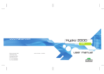
The universal fluid flow monitoring system
User manual DDS3v10
WHAT DDS3v10 will do for you
The DDS3 turbine based flow monitoring system has been serving the
water/alcohol injection market for many years. It gives added protection to a tuned engine should the system fails to deliver fluid correctly.
The DDS3v10 is equipped with a new flow sensor. The redesigned
internals allow wider flow range and better transient response. The
sensor element is now placed in a metal housing rather in plastic.
The electronics department has also been extensively revised to ease
connectivity with third party systems. In most cases, only a single wire
is needed. There are three Fail-safe output options to protect your
engine.
Page 3
Contents:
Dash Gauge
Page
4
5
Checking the DDS3v10 box contents
Installation for long term reliability
Flow sensor
6-7
DDS3v10 Dash Gauge functions
8-9
Junction board pinout descriptions
Junction Box
10-11 Junction board function index
12-13 Junction board pinout descriptions
Advanced
14-15 Advance system configuration
Wiring guides
16
17
Interfacing other Aquamist systems
Non-Aquamist system interface
18
19
Simple DIY system
Wiring details Guarantee and Warranty
Appendix
Page 4
Checking the DDS3 contents
DASH
GAUGE
DDS3v10
BOARD
FLOWJUNCTION
PUMP
SENSOR
RELAY
+12V WFS 13
DDS3-v10
2x 1/8BSP to 1/4" hose
(for third party system)
Fluid Flow management system
and failsafe controller
designed and made in England
for SAL
ER
V
I
UN use
assortment of
coloured hook-up
wires for
interconnection
usage
water level sensor
FLOW SENSOR
Part No. 806-428
Flow range: 100-1200ml/min
Output range: 0.5-4.5VDC
3A FUSE
2x bags
Serial No: 22100
Made by ERL Ltd. Sussex England
Please check and ensure all the above contents are in the box
Installation for long-term reliability
Page 5
The Junction box:
This is the heart of the system and must be installed
in a dry location, preferably sited close to the glove
compartment. Do not install it in the engine compartment, (It has been done !)
Assuming all cables from various locations are
routed to the junction box neatly. Please label the
flow sensor cable to prevent it from wrongly identified with the 4-core cable from the truck area, Once
marked, the cables and wires can be cable tided.
The Flow sensor:
The location of this sensor is most critical to overall
system reliability. It is normally located it in the engine compartment. But there is no reason why it
can’t be spliced into any where between the pump
outlet and jets/nozzles.
The sensor must be installed in a cool area, well
away from the a heat source. Bulkhead/fire wall is
not a good location as most heat is flowing towards
it during motoring. Avoid location near any electromagnetic components such as the ignition coil,
solenoid valves and electronic motors.
It is very important that the hose is cut cleanly with
a razor blade to retain the “roundness”. Side cutter
produces a semi-round hose end, major leak will
result sooner or later. The hose exiting the fitting
must be straight so that the hose is not distorted and
will be badly affected in a hot environment. Again, in
time it will develop a leak.
The most common mistake at this point is cutting
the bundled cables very short to improve tidiness.
Please don’t. Allow a minimum of 2 feet so that the
junction box is accessible when a problem occurs,
Longer cable length will not degrade the system
performance at all.
The Tank level sensor:
Avoid locating the sensor tip close to a washer motor. The motor magnet will affect the sensor to read
properly. The sensor can be installed 3/4 way down
the tank, Preferably at the rear facing wall of the tank.
A 23mm burr-free hole must be used to ensure good
seal. Never over tighten or the seal will split, just tight
enough to prevent leakage, no more.
This is the most important section of the
DDS3 chapter. Please do not skip reading this
part.
The 52mm Dash Gauge:
Location is not too critical as long as it is in view of
the driver. There isn’t too many pitfall on this.
DDS3v10 Dash Gauge Functions
1
6
7
2
3
8
4
9
5
10
1. 8-element Bargraph Display (80-1800ml/min)
Each segment is equivalent to a percentage of the total
flow of the sensor scaled by the SC potentiometer.
2. “S” indicates the presence of sensor.
The letter “S” (sensor) must be lit after power up and
stay on to show the sensor is functioning correctly.
3. Water injection system ON led
This led comes on the when the system is switched on
and in readiness to inject. .
Page 6
4. Water Level led (yellow)
(This LED has three functions)
a. During “power on delay” period:
This LED will activate for approximate for 10
seconds during the system-on delay (v10) before the main system turns on.
b. During normal operation period:
- This LED is on during the safe-fail activation
- Water level low (intermittent flashes)
c. Led lit after the gauge is switched off:
- If the water level sensor is activated for over
20 seconds.
- Fail-safe output is in the active state (10.6).
5. SC (Sensor Calibration)
20-stepped potentiometer allow user to scale
the flow sensor to give an ideal visual indication
of a given flow rate. Ideally set the led to display 5-6 bars at full flow.
6. Backlit flow legend
Legend displays % of full scale of 8-bars
7. “B” Boost Enabled led
When the flow falls inside the fail-safe window
after system trigger, this “B” led will activated.
Useful indicator of the WL and WH setting.
Page 7
8. Water injection enable button
Due to extra power level achieved under WI, user
may want to reduce the power to the wheels in less
than ideal driving conditions. Disabling the WI will
reduce boost to wastegate bleed valve setting (if
fitted) as well as switching to a less aggressive MAP
on custom engine management.
9. Over-range setting potentiometer (WH)
It is just as important to monitor over-range conditions as well as under-range flow conditions. If a leak
develops close to the water jet and starves the
engine of the water, the user must know this condition. A 20-stepped potentiometer allows accurate
and repeatable adjustment range.
10. Under-range setting potentiometer (WL)
This setting can indicate partial blockage and trapped
air inside a delivery hose. Again 20-stepped potentiometer is employed. Each click represents a fixed
portion of the window
width of 8-bars.
failsafe window width
coverage (20-clicks)
WL covers the lower 4
bars and the WH covers the upper 4 bars.
Figure on the right illustrates the span of
the coverage. Setting
is very simple once SC
WL
WH
is calibrated.
NOTE:
In order to make the fail-safe adjustment easier, it is
recommended to set the bargraph to display 5-6
bars at maximum flow. This way, the fail-safe window can span from the centre outwards.
If the WL and WH is set at 12 O’clock, the fail-safe
window is approximately spanned between 2-7bars.
A good starting point.
Minor trimming for the WL is necessary if the water
injection trigger point is set to commence earlier.
The v10 gauge will display the activation of the
“fail-safe” with two leds:
Further useful hints:
“B” led (right of the bargraph) will active if the flow
is inside the fail-safe window during injection period.
The yellow led (water level) will activate if the flow
is outside the fail-safe window during injection.
As soon as the “fail-safe ” is tripped, there will be a
4 second reset period before it resets. If the fail-safe
drops boost, expect 4 seconds of low boost. The
same will apply for fail-safe-induced map switch.
When gauge is off, expect low boost and safe map
unless the board is re- configured. (page15.B).
DDS3 junction board pinout descriptions
1. RJ-45 socket for dash gauge:
The DDS3v10 uses a RJ45 connector to link up with
the Dash gauge,
2. Inline flow control valve:
This output can be used to switch an inline solenoid
valve to control flow. Output current is limited to 1
Amp. It is activated by the signal applied to the
PWM (pin17) or MAP (pin18) input.
User can set the triggering point by using the “Tripadj” potentiometer near the bottom of the junction
board.
3. External Anti-CEL dummy load resistor:
A more powerful anti-CEL dummy resistor can be
connected to this output when excessive heat is
produced by the on-board dummy resistor. This
option only applies if pin 9-10 is used for cutting the
PWM signal to a boost control solenoid valve in the
event of fail-safe or prolonged “gauge-off period”.
4. MAP switching signal output:
Fail-safe output for map switching usage. This output is about 5V and switch to 0v upon fail-safe
activation. The signal is short circuit proof with a
current limit of 5mA. If an alternative or an inverted
Page 8
output signal is required. this output pin can be
reprogrammed via a set of soldering pad on the
underside of the circuit board.
Please go to page 15, section C/D for a more detailed description of how this can be done.
5. Fail-safe window output (SW GND)
When flow signal falls inside the fail-safe window,
pin7 will switch to ground immediately. This output
can be used to activate a solenoid valve to increase
boost pressure. This output can also be used to
switch MAP (GND active) on an ECU.
6. Voltage free relay outputs
There are three terminals representing a set of
voltage-free “change-over” contacts from a relay if
anti-CEL -dummy resistor jumper link is un-used.
(p10.6). M-SW1 is the “wiper” or “common” pin.
M-SW1 and M-SW-0 contacts are opened normally
until fail-safe is triggered or gauge is switched off
M-SW1 and M-SW-3 contacts are closed normally
until fail-safe is triggered or gauge is switched off.
Page 9
7. Led brightness for night driving (p.9)
When pin 19 is linked to the headlamp switch, this
potentiometer enables user to adjust the brightness
level of the gauge leds.
8. System trigger point adjustment (p.9)
This potentiometer sets the triggering point of the
injection system.
In PWM mode, the figure on
the left indicates the IDC trip
point in 6% steps.
Most common onset point is
42%, (12‘o’clock).
In MPS mode, the figure on
the left will help to identify
the trip point of a 12 to 72%
Manifold Pressure Sensor. To
translate the signal % to PSI,
please see the table below:
36%
42%
48%
32%
54%
24%
60%
12%
66%
12%
36%
PWM MODE
42%
72%
48%
32%
54%
24%
60%
12%
66%
12%
MPS MODE
72%
%
-11 -9.3 -7.6 -5.8 -4.1 -2.3 -0.6 1.2 2.9 4.6 5.6 PSI
-9.3 -6.7 -4.1 -1.5 1.7 3.8 6.4 9.0 11.6 14.2 16.8 PSI
.Trip-adj 12 18 24 30 36 42 48 54 60 66 72
2-bar
3-bar
MAP sensor conversion table: from % to PSI (shaded = vacuum)
9. LED (green) to monitor IDC
This led will active when a PWM signal is successfully detected on pin17. It should pulse in unison
with the frequency and grows brighter as the duty
cyle % increases. This led should not be lit before
cranking. After the engine has started, it should
pulse in time with engine speed,
If the DDS3 is used as a failsafe to a third party
WAI system, this led will only pulse when the
PWM pump is activated under normal injection
events.
10. Selecting external dummy resistor
Selecting ext/int dummy resistor. The on-board
Anti-CEL resistor is rated for intermittent usage
during fail-safe activation. In the event of prolong
activation, it will get very warm. To avoid excessive heat build up, it is recommended to use an
external dummy resistor for this purpose,
The external resistor is not supplied with the kit
but it is widely available in electronics store. The
resistor should be 39 ohms, 10W-25W in metal
body.
NOTE: If anti-cel is not necessary, please leave it
on the XDR position or remove the link completely.
DDS3 Junction board
Page 10
Pin function directory
This label
defines the
unit is preset
for a unique
WAI system
1
2
3
4
5
6
8
9
+12V WFS
0V WFS
13
14
15
16
PWM IN
MPS IN
DIMMING
17
18
19
20
21
22
23
24
25
HSV +
HSV XDR +
XDR MAP SW
BCV +
BCV M-SW-0
M-SW-1
M-SW-2
1
2
3
4
5
6
7
8
9
10
P.RELAY+
P. RELAY+12V IN
+0V IN
DIM-ADJ
MAP SWITCH
RELAY 12v
1A MAXIMUM
7
DDS3-v10
SYS ON
XDR
IDR
10
16
DUMMY
LOAD
17
18
11
12
13
14
15
Page 11
This label
defines the
unit is preset
for a unique
WAI system
1
2
3
4
5
6
8
9
+12V WFS
0V WFS
13
14
15
16
PWM IN
MPS IN
DIMMING
17
18
19
20
21
22
23
24
25
HSV +
HSV XDR +
XDR MAP SW
BCV +
BCV M-SW-0
M-SW-1
M-SW-2
1
2
3
4
5
6
7
8
9
10
P.RELAY+
P. RELAY+12V IN
+0V IN
DIM-ADJ
MAP SWITCH
RELAY 12v
1A MAXIMUM
7
DDS3-v10
SYS ON
XDR
IDR
10
16
DUMMY
LOAD
17
18
11
12
13
14
15
1, RJ-45 socket for dash gauge (p.8)
2. Inline flow control valve (p.8)
3. External Anti-CEL dummy load resistor (p.8)
4. MAP switching signal output (p8)
5. Boost Control valve output (p.8)
6. Voltage free relay outputs (p.8)
7. Led brightness for night driving (p.9)
8. System trigger point adjustment (p.9)
9. LED (green) to monitor IDC (p.9)
10. Selecting external dummy resistor (p.9)
11. 4-core cable to turbine flow sensor (p.12)
12. System trigger signal input (p.12)
13. +12V input to enable led dimming (p.12)
14. Tank level/pump control output (p.12)
15. Main power input (fused), IGN.SW #2 (p.12)
16. Internal Anti-CEL dummy resistor (p.12)
17. LED (red) to show system activation (p.13)
18. User selectable system configuration (p.13)
Page 12
11. 4-core cable to turbine flow sensor
Please ensure the stripped wires are twisted
without any loose strands before insertion into
the terminal block connector.
12. System trigger signal input
Choice of two system triggering signal inputs.
Selectable by jumper links (page13.18)
PWM IN (pin17): It reads and translates any
negative going pulses such as fuel injector or
PWM based pump speed controller in to a reference signal to trigger the system and fail-safe
circuitry.
The system is factory set to detect negative
PWM signals. Some pump speed controller uses
a positive PWM switching driver, you need to
re-configure the DDS3 circuit board manually,
(p15.F).
MPS-IN (pin18): 0-5V input signal for triggering
the system instead of PWM. This type of signal
is normally associated with MAP, MAF and TPS
sensors.
The trigger point of the above is set by the Tripadj potentiometer (#8).
13. +12V input to enable led dimming
A 12V signal at this input enables the uses to set the
brightness of gauge (p12.7). It is normally wired to the
head lamp switch so the gauge will automatically dim
during night driving.
14. Tank level/pump control output
These four connections control the delivery pump and
detects water tank fluid level. Control signals are
transmitted via a ~5M of 4-core cable to the trunk area.
15. Main power input (fused), IGN.SW#2
It is important the 12V power is only active at ignition
switch position #2. Ideally, it should be wired to the
same +12V supply to the fuel injectors.
16. Internal Anti-CEL Dummy resistor
If the stock ECU-controlled boost valve is disconnected by the DDS3 during a fail-safe activation, a
CEL (check engine light) is often illuminated.
To prevent this from happening, A dummy resistor is
used to create an artificial load of a boost control
valve.
During this period, the resistor will warm up. If heat
is a concern, use an external resistor, (see page8.3)
Page 13
17. LED (red) to show system activation
This “SYS ON” red led actives when the PWM/MPS
input signal reaches the “trip adj” setting. The system will commence injection.
F. Set
F. Set
18. User selectable system configuration
Figure on the right shows a
see text -> 1 2 3 4 5
set of default user selectaDIM-ADJ
ble jumper links for setting
up the triggering mode and
manual system test. Read
SYS ON
on for further details
1. MPS (Manifold Pressure Sensor) MODE link:
Selecting this link instead of the default “PWM” link
changes the system’s triggering mode. Now the
system will be looking at the MPS signal (0-5V) at pin
18 to turn the system on.
2. PWM (Pulse Width Modulation) MODE link:
PWM MODE (Factory set). The system looks for
“switch to ground” PWM signal from the pin17 to
turn the fail-safe circuitry and W/A injection on. For
“positive edge trigger” see “Advance setting"
(Page15.F). Upon successful detection of PWM
pulses, the Green led will pulse in time with the
incoming PWM signal.
3. PRK (Parking unused jumper link)
This link space is for parking an un-used jumper link
socket. No other usage.
4. CAL (Calibration Simulation. Default = unlinked)
Linking this pin turns the “SC” potentiometer into a
flow sensor simulator. Fully clockwise for minimum
water flow. Useful to check the fail-safe window
width. “B” led will activate when the simulated flow
is inside the window
5. TST (Manually test. Default= unlinked)
This link is useful for testing the system without
driving the car at full boost and RPM. When this link
is shorted, it simulates a 100% IDC signal appearing
at the PWM input terminal (pin17).
Warning!!! Linking this pin will start the pump and
energise the lnline valve, resulting in 100% maximum fluid delivery to the water jet/jets.
Do not activate this link for more than 5-10 seconds
at a time for risk of burning up a solenoid valve
designed for pulsing purpose use only.
Remove this link as soon as the manual system test
is completed.
Advance system configuration (solder link)
+
+
A B C D E F
Page 14
Advance system configuration (solder link)
The DDS3v10 is pre-configured at the factory for a
specific application. When in doubt, please check the
round label on the lid of the box or the small label on
the RJ45 socket at the top right of the junction
board. (factory default: “for Universal fail-safe use”)
Page 15
switched off at the gauge, only if you are using pin
9/10 to reduce boost to wastegate setting after
fail-safe activation,.
If the user wishes to change the original setting, this
is the section to explain it all. You will require a small
tipped soldering iron and a small pointed tool.
C/D: MSW - Map Switch polarity (default= D-linked)
The factory default output is preset to give a 0V
output upon a fail-safe activation. Otherwise the
output will stay at ~8V.
As seen from the PCB figure on the left. All the user
configurable links are marked with alphabetised
circles.
To invert this output to give out a +8v signal upon a
fail-safe activation, un-solder the pad D(-) and solder
link pad C(+) to the long soldering pad.
Some pads are pre-linked from factory. If you need
to change those, pick off the thin track (pointed tool)
and solder link the alternative solder pads.
E: CMP Clamping MSW signal (default=clamped)
Solder linking this pin will clamp the above MSW
signal down to 4.7V, suitable for most digital devices. It is factory linked to give 4.7V.
A: WLS - Water Level Sensor (default=linked)
Pick off the thin circuit track if you do not wish the
tank level sensor to disable the system after 10-20
seconds of low level reading. (not recommended),
B: DHB - Disable High Boost (default=linked)
Pick off the thin circuit track if you want to retain high
boost or “Aggressive MAP” after the system is
F: PWM MODE polarity (default=negative switched)
To change the PWM detection polarity to positive,
pick off the thin track and solder-link the “+” pad to
the long pad. This mode is rarely used except the
DDS3 is used for monitoring WAI system using a
positive PWM signal to control the water pump
speed. (For example, Snow and Devilsown system)
Page 16
Other Aquamist system interface
DDSS3v10 to Aquamist System1s and System2d
Aquamist
100
200
300
DDS3-v10
for
Universal
use
400ml/m
FLOW
W. INJECTION
WL
FLOW SENSOR
DDS3v10 JUNCTION BOARD
+12V WFS
0V WFS
WATER LEVEL
SC
806-428
4-WAY/22AWG
CABLE (2M)
Part No. 806-428
Flow range: 100-1200ml/min
Output range: 0.5-4.5VDC
13
Serial No: 22100
Made by ERL Ltd. Sussex England
14
15
WH
1
2
3
M a de in ngland
E
4
5
6
WATER
TANK
IN TRUNK
806-281
806-270
8
9
10
SYSTEM
ACTIVE
1s or 2d
system
16
PWM IN
MPS IN
DIMMING
17
18
19
20
12V TO
DIM
21
P.RELAY+
P. RELAY+12V IN
+0V IN
22
23
3A FUSE
24
806-157
GND
SYS ON
XDR
IDR
+12V IGN SW
25
DIM-ADJ
MAP SWITCH
RELAY 12v
1A MAXIMUM
Fail-safe output (pin 9, 10)
terminals. this set of relay
contact goes open circuit
when a fault is detected.
7
HSV +
HSV XDR +
XDR MAP SW
BCV +
BCV M-SW-0
M-SW-1
M-SW-2
39R
DUMMY LOAD
TO AVOID CEL
USE
MPS
Non-aquamist system interface
The DDS3 Bargraph will read and display the
flow of any WI system on the market providing the
flow sensor is coupled up properly. But if you want
it to detect problems such as low or excessive flow,
you must tell it when to look. Equipped with two
triggering modes, it is just a matter of choosing
which mode is better for your system.
Page17
power applications. Set the jumper link to “PWM”
Mode
F. Set
Fails-afe triggered by pump speed signal:
Most progressive WI
system controls the
pump speed via the
negative terminal, by
Fail-safe triggered by MAP / MAF sensor:
setting the DDS3 to
Ensure the jumper link is set to “MPS”Mode.
‘PWM’ mode, failThe DDS3 will now detect
safe circuitry can actiMAP/MAF sensor voltage. DIM-ADJ
vated at any rpm of
Adjustable triggering point bethe pump. Just splice
tween 12% to 72% of the
the
trigger
wire
0-5V range, For a 2-bar map
(pin17) into the negasensor, atmospheric is about
SYS ON tive terminal of the
2.5V.(see page 9.8 for details).
pump. This is the best
Fail-safe triggered by Fuel injection %:
way to confirm the system is working properly.
This mode is very useful because it is looking for a
point on your power curve where the engine is most For systems that control the pump speed via the
stressed, Monitoring the presence of water/alcohol positive terminal of the pump, for example Snow
flow in this area is very important. As the Fuel duty Performance and Devilsown, you need to recycle % more or less mirroring the power output of configure the DDS3‘s circuit board for this. See page
the engine, This mode is more suitable for high 15.F .
Page 18
Simple DIY system
DIY system example with fail-safe using the DDS3v10
Aquamist
100
200
300
DDS3-v10
for
Universal
use
FLOW
W. INJECTION
WATER LEVEL
SC
INSTALL IN ENGINE BAY
400ml/m
WL
4-WAY/22AWG
CABLE (2M)
+12V WFS
0V WFS
WH
2
M a de in E ng la n d
3
4
5
6
7
8
9
10
HSV +
HSV XDR +
XDR MAP SW
BCV +
BCV M-SW-0
M-SW-1
M-SW-2
Serial No: 22100
13
N. CLOSED
SOLENOID
VALVE
806-234
14
Made by ERL Ltd. Sussex England
16
PWM IN
MPS IN
DIMMING
TO FUEL INJECTOR PULSE PIN
MPS TRIGGER SIGNAL 0-5V
17
18
19
20
12V TO
DIM
21
P.RELAY+
P. RELAY+12V IN
+0V IN
22
23
3A FUSE
24
+12V IGNITION SWITCH
25
DIM-ADJ
87
MAP SWITCH
RELAY 12v
1A MAXIMUM
GND
86
30
39R
SELECTING
DUMMY LOAD
TRIGGER MODE
TO AVOID CEL
SYSTEM
ACTIVE
WATER
TANK
IN TRUNK
806-281
806-270
30A
RELAY
806-276
85
SYS ON
XDR
IDR
VENTING THE TANK EXTERNALLY IF
HIGH CONCENTRATION OF METHANOL
IS USED TO AVOID BUILD-UP FUME.
METHANOL FUME IS POISONOUS BY
INHALATION.
FLOW SENSOR
Part No. 806-428
Flow range: 100-1200ml/min
Output range: 0.5-4.5VDC
15
1
Fail-safe output (pin 9, 10)
terminals. this set of relay
contact goes open circuit
when a fault is detected.
806-234
DDS3v10 JUNCTION BOARD
806-428
BLK
WATER PUMP
WITH INTERNAL
BY-PASS VALVE
TO AVOID
PULSING.
RED BLK
BATTERY
Page 18
Appendix
In Car Dash Gauge (8-core cable)
Pin
Colour Size
Description
1
24awg +12V power supply to gauge
2
24awg Flow Sensor output voltage
3
24awg 0V power supply to gauge
4
24awg Internal communication signal
5
24awg Float Sensor from water tank
6
24awg Flow Sensor calibration output voltage
7
24awg Night driving dimming connection
8
24awg Wastegate bleed valve option (SW-)
@12V max.
Flow Sensor (4-core cable)
Pin
Colour Size
Description
1
Red
24awg +12V power supply of Flow Sensor
2
Blue
24awg 0V power supply of Flow Sensor
3
Yellow 24awg Flow Sensor output voltage
4
Green 24awg Flow Sensor calibration input voltage
Electrical parameter
250mAmax@12v
0-5 VDC @10mA
250mAmax@12v
Ground active
5-0 VDC @1mA
+12V active
1A
Electrical parameter
30mA @ 12v
0V Ground
0-5VDC@10mA
5-0VDC@1mA
DDS3 Junction Box (25-ways - Pin 1= top left corner. Pin 25 bottom right corner)
Pin
Colour Size
Description
Electrical parameter
RJ45
------ 8-core Same as Dash Gauge Above
-----1
Red
22awg +12V power supply to Solenoid valve
+12V, 1A fused
2
Brown 22awg Switching to ground for Solenoid Valve
1A maximum
3
D.Grey 22awg Extending Dummy resistor (+12V side)
1A maximum
4
D,Grey 22awg Extending Dummy resistor (EMS)
1A maximum
5
Orange 22awg Programmable Map switch signal
5mA signal
6
Red
22awg Boost control valve +12V supply
1A max
7
Brown 22awg Boost control valve switch to ground
600mA max
8
Black 22awg Normally closed relay contact (fail-safe)
1A max
9
Grey
22awg Wiper/common relay contact
1A max
10
White 22awg Normally opened relay contact
1A max
11-14 ------ 4-core See 4-core cable description above
-----15
Green 22awg FIDC detect or MAP sensor
Wave input
16
Blue
22awg MAPsensor or 0-5v based sensor
0 to 5V input
17
Pink
22awg Night driving dimming connection
+12V active
18
Yellow 22awg To ground when tank is empty
0.25A maximum
19
Green 22awg Common ground
0.25A maximum
20
Red
22awg Priming pump +12V supply (0.5A FUSED) 0.5A maximum
21
Blue
22awg Priming pump ground switch (active)
1A maximum
22
Red
20awg +12V switched power supply for all
3A maximum
23
Black 20awg 0V ground supply for all
3A maximum
GUARANTEE
ERL guarantees, at our option, to replace faulty goods supplied or repair the same, subject to the claim made in writing
to us within 12 months after the sale by us, or for such other
period as may be indicated by us for specific products in lieu
of any warranty or condition implied by law as to the quality
or fitness for any particular purpose of the goods.
Any claim against us must be made to us in writing within
the period of 12 months after the sale by us , or our agents,
or our distributors of goods in question (or such other period
as may be indicated by us) and any goods to which the claim
relates must be returned to us within that period suitably
packaged and cleaned and, with any particular instructions
which we may have notified to you at the time of supply.
Original invoice, the nature of any claimed defect must accompany the goods in question prior to despatch to us.
If these requirements are not complied with our Guarantee
shall not apply and we shall be discharged from all liability
arising from the supply of defective goods.
LIABILITY
We shall not be under any liability whether in contract, or
tort or otherwise and whether or not resulting from our negligence or that of our employees, in respect of defects in
goods supplied or for any damage or loss resulting from
such defects.
We shall not be under any liability for damage, loss of expense resulting from failures to give advice or information
or giving the incorrect advice or information whether or not
due to our negligence or that of our employees.
In no event shall any breach of contract on our part or tort
(including negligence) or failure of any time on our part that
of our employee give rise to liability for loss of revenue or
consequential loss or damages arising from any cause whatsoever.
Note: ERL reserves the right to make changes to our products without notice in order to improve design performance
and reliability.
ERL ltd
Iroko House
Bolney Ave
Peacehaven
East Sussex
BN10 8HF
England