1
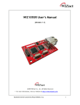
WIZ110SR User’s Manual (Version2.0) ©2008 WIZnet Co., Ltd. All Rights Reserved. ☞ For more information, visit our website at http://www.wiznet.co.kr APC Hero 01480 226600 [email protected] WIZnet’s Online Technical Support If you have something to ask about WIZnet products, write down your question on Q&A Board in WIZnet website (www.wiznet.co.kr). WIZnet will give an answer as soon as possible. CLICK Copyright © WIZnet All Rights Reserved APC Hero 01480 226600 [email protected] WIZ110SR | 2 page COPYRIGHT NOTICE Copyright 2008 WIZnet, Inc. All Rights Reserved. Technical Support: [email protected] Sales & Distribution: [email protected] For more information, visit our website at http://www.wiznet.co.kr Copyright © WIZnet All Rights Reserved APC Hero 01480 226600 [email protected] WIZ110SR | 3 page Table of Contents 1. 2. INTRODUCTION .......................................................................................... 6 1.1. KEY FEATURES .......................................................................................... 6 1.2. SPECIFICATION .......................................................................................... 6 1.3. PRODUCTS CONTENTS .................................................................................. 7 WIZ110SR BOARD ....................................................................................... 8 2.1. BLOCK DIAGRAM ........................................................................................ 8 2.2. CONFIGURATION TOOL .................................................................................. 9 3. FIRMWARE UPLOAD ................................................................................... 19 4. SERIAL CONFIGURATION .............................................................................. 21 5. 6. 7. 4.1. SERIAL COMMAND FORMAT ............................................................................ 21 4.2. WIZ110SR CONFIGURATION WITH SERIAL COMMAND ................................................. 24 DEMONSTRATION AND TEST ......................................................................... 26 5.1. HARDWARE INTERFACE ................................................................................ 26 5.2. TESTING SERIAL TO ETHERNET FUNCTION ............................................................. 26 WIZ110SR HARDWARE SPECIFICATION ............................................................ 28 6.1. PARAMETERS .......................................................................................... 28 6.2. SPECIFICATION ........................................................................................ 28 6.3. BOARD DIMENSIONS AND PIN ASSIGNMENT ............................................................. 28 WARRANTY .............................................................................................. 30 Copyright © WIZnet All Rights Reserved APC Hero 01480 226600 [email protected] WIZ110SR | 4 page FIGURES Figure 1. Block Diagram ........................................................................... 8 Figure 2. Configuration Tool (Network Config) ............................................... 9 Figure 3. PPPoE Connection Process in Serial Console ................................... 10 Figure 4. TCP Server mode ..................................................................... 11 Figure 5. TCP Client mode ...................................................................... 12 Figure 6. UDP mode.............................................................................. 13 Figure 7. Configuration Tool (Serial Config.) ................................................. 15 Figure 8. Configuration Tool (Option Config.) ................................................ 16 Figure 9. Option Mode for Password Configuration ......................................... 18 Figure 10. Board Search Window .............................................................. 19 Figure 11. Open dialog box for uploading ..................................................... 20 Figure 12. Firmware uploading window ....................................................... 20 Figure 13. Complete Uploading ................................................................ 20 Figure 14. WIZ110SR Interface................................................................. 26 Figure 15. Device Terminal ...................................................................... 27 Figure 16. WIZ110SR Dimension ................................................................ 28 Figure 17. RJ-45 PIN Assignment.............................................................. 29 Tables Table 1. Specification............................................................................... 7 Table 2. Products Contents ....................................................................... 7 Table 3. Serial Configuration Frame Format.................................................. 21 Table 4. Serial Configuration Reply Frame Format .......................................... 21 Table 5. Serial Configuration STX & ETX ..................................................... 21 Table 6. Serial Configuration Reply Code ..................................................... 21 Table 7. Serial Configuration Command Code ............................................... 23 Table 8. Serial Configuration Testing Process ................................................ 25 Table 9. Testing Environment of WIZ110SR .................................................. 26 Table 10. RS-232 PIN Assignment ............................................................. 29 Copyright © WIZnet All Rights Reserved APC Hero 01480 226600 [email protected] WIZ110SR | 5 page 1. Introduction WIZ110SR is a gateway module that converts RS-232 protocol into TCP/IP protocol. It enables remote gauging, managing and control of a device through the network based on Ethernet and TCP/IP by connecting to the existing equipment with RS-232 serial interface. In other words, WIZ110SR is a protocol converter that transmits the data sent by serial equipment as TCP/IP data type and converts back the TCP/IP data received through the network into serial data to transmit back to the equipment. 1.1. - Key Features Direct Connection to the Serial Device Adding Network Function Simply and Quickly Providing Firmware Customization - System Stability and Reliability by using W5100 Hardware Chip - Supports PPPoE Connection - Supports Serial Configuration – with Simple and Easy command - Supports Password for the Security - Configuration Tool Program - 10/100 Ethernet Interface and max 230Kbps Serial Interface - RoHS Compliant 1.2. Specification ITEM MCU Description 8051 compliant (having internal 62K Flash, 16K SRAM, 2K EEPROM) TCP/IP W5100 (Ethernet MAC & PHY Embedded) Protocol TCP, UDP, IP, ARP, ICMP, MAC, DHCP, PPPoE, DNS Network Interface 10/100 Mbps(Auto detection), RJ-45 Connector Serial Interface RS232(DB9) Serial Signal TXD, RXD, RTS, CTS, GND Parity : None, Even, Odd Serial Parameters Data Bits : 7,8 Flow Control : None, RTS/CTS, XON/XOFF Speed : up to 230Kbps Copyright © WIZnet All Rights Reserved APC Hero 01480 226600 [email protected] WIZ110SR | 6 page Input Voltage DC 5V Power Consumption Under 180mA Temperature 0C ~ 80C (Operation), -40C ~ 85C (Storage) Humidity 10 ~ 90% Table 1. Specification 1.3. Products Contents WIZ110SR Board CD (Optional / including Configuration Tool Program, Firmware and Manual) LAN Cable (Optional) 5V Power Adaptor (Optional) Table 2. Products Contents ☞ If there is any missing item, contact to the shop where you purchased. ☞ The optional items should be purchased separately. Copyright © WIZnet All Rights Reserved APC Hero 01480 226600 [email protected] WIZ110SR | 7 page 2. WIZ110SR Board 2.1. Block Diagram Figure 1. Block Diagram WIZ110SR is a protocol converter that transmits the data sent by serial equipment to Ethernet and converts back the TCP/IP data received through the network into serial data to transmit back to the equipment. When the data is received from serial port, it is sent to W5100 by MCU. If any data is transmitted from Ethernet, it is received to the internal buffer of W5100, and sent to the serial port by MCU. MCU in the module controls the data according to the configuration value that user defined. Copyright © WIZnet All Rights Reserved APC Hero 01480 226600 [email protected] WIZ110SR | 8 page 2.2. 2.2.1. Configuration Tool Network Configuration ⓐ ⓑ ⓓ ⓔ ⓕ ⓖ ⓒ 100 ⓗ ⓘ ⓚ ⓙ ⓛ ⓜ Figure 2. Configuration Tool ⓝ ⓞ ⓟ ⓠ (Network Config) ⓐ Version : Displays firmware version. You can use PPPoE, Serial Command, Password function from firmware Ver.2.5. ⓑ Enable Serial Debug Mode : If this mode is checked, you can monitor the status and socket message of WIZ110SR (listen OK, connect fail etc.) through serial terminal. If Debug mode is on, debug message can cause abnormal operation of the serial device. Therefore, just use this mode only for Debug mode. ⓒ Board List : If you click “Search” button, all the MAC addresses on a same subnet, will be displayed. Copyright © WIZnet All Rights Reserved APC Hero 01480 226600 [email protected] WIZ110SR | 9 page ⓓ IP Configuration Method: Select IP setting mode, you can select among Static, DHCP, PPPoE mode. Static: “Static” is the option for setting WIZ110SR with static IP address. First select MAC address that you want to set it as static IP in „board list‟. Then, the “Local IP, Subnet, Gateway boxes are enabled. Input Static IP address and click “setting” button. Then IP is set as you want. (PPPoE ID, Password box will be disabled) DHCP: Set this option to use DHCP mode. First, check „DHCP‟ and click „Setting‟ button. If IP address is successfully acquired from DHCP server, the MAC address will be displayed on the board list. (It takes some time to acquire IP address from DHCP server) When a module on the board list is selected, IP address, Subnet mask and Gateway are displayed. If module could not acquire network information from DHCP server, IP address, Gateway Address and Subnet mask will be initialized to 0.0.0.0. PPPoE : WIZ110SR supports PPPoE for ADSL user. When you select PPPoE in “IP Configuration Method” PPPoE ID and Password box will be enabled. 1. To set PPPoE, connect PC to WIZ110SR directly and execute Configuration Tool program on PC. (Configuration Tool version should be 2.1 or above) 2. Select „PPPoE‟ of the “IP Configuration Method” tab and input ID & Password. 3. Click “setting” button to apply. 4. Connect Module to ADSL Line. 5. If “Enable Serial Debug Mode” is selected, you can see PPPoE access status via Serial console. Figure 3. PPPoE Connection Process in Serial Console Copyright © WIZnet All Rights Reserved APC Hero 01480 226600 [email protected] WIZ110SR | 10 page ⓔ Local IP/Port : WIZ110SR‟s IP address and Port number for network connection ☞ Be sure to input correct network information. If you input incorrect IP address, it can cause network collision or mal-function. ⓕ Subnet : WIZ110SR‟s subnet mask ⓖ Gateway : WIZ110SR‟s Gateway address ⓗ PPPoE ID/Password : If you select „PPPoE‟ mode, input ID/Password which you received from ISP company. ⓘ Server IP/Port : When WIZ110SR is set as “Client mode” or Mixed mode”, server IP and port should be set. WIZ110SR attempts to connect this IP address. ⓙ Network mode : client/server/mixed : This is to select the communication method based on TCP. TCP is the protocol to establish the connection before data communication, but UDP just processes the data communication without connection establishment. The Network mode of WIZ110SR can be divided into TCP Server, TCP Client and Mixed mode according to the connection establishing method. At the TCP server mode, WIZ110SR operates as server on the process of connection, and waits for the connection trial from the client. WIZ110SR operates as client at the TCP Client mode on the process of connection, and tries to connect to the server’s IP and Port. Mixed modes supports both of Server and Client. The communication process of each mode is as below. <TCP server mode> Figure 4. TCP Server mode At the TCP Server mode, WIZ110SR waits for the connection requests. Copyright © WIZnet All Rights Reserved APC Hero 01480 226600 [email protected] WIZ110SR | 11 page TCP Server mode can be useful when the monitoring center tries to connect to the device (where WIZ110SR is installed) in order to check the status or provide the commands. In normal time WIZ110SR is on the waiting status, and if there is any connection request (SYN) from the monitoring center, the connection is established(ESTABLISH), and data communication is processed (Data Transaction). Finally connection is closed (FIN). In order to operate this mode, Local IP, Subnet, Gateway Address and Local Port Number should be configured first. As illustrated in the above figure, data transmission proceeds as follows, 1. The host connects to the WIZ110SR which is configured as TCP Server mode. 2. As the connection is established, data can be transmitted in both directions – from the host to the WIZ110SR, and from the WIZ110SR to the host <TCP client mode> Figure 5. TCP Client mode If WIZ110SR is set as TCP Client, it tries to establish connection to the server. To operate this mode, Local IP, Subnet, Gateway Address, Server IP, and Server port number should be set. If server IP had domain name, use DNS function. In TCP Client mode, WIZ110SR can actively establish a TCP connection to a host computer when power is supplied. As illustrated in the above figure, data transmission proceeds as follows: 1. As power is supplied, WIZ110SR board operating as TCP client mode actively establishes a connection to the server. 2. If the connection is complete, data can be transmitted in both directions – from the host to the WIZ110SR and from WIZ110SR to the host Copyright © WIZnet All Rights Reserved APC Hero 01480 226600 [email protected] WIZ110SR | 12 page <Mixed mode> In this mode, WIZ110SR normally operates as TCP Server and waits for the connection request from the peer. However, if WIZ110SR receives data from the serial device before connection is established, it changes to the client mode and sends the data to the server IP. Therefore, at the mixed mode, the server mode is operated prior to the client mode. As like TCP Server mode, the Mixed mode is useful for the case that the monitoring center tries to connect to the serial device (in which WIZ110SR is used) to check device status. In addition to this, if any emergency occurs in the serial device, the module will change to Client mode to establish the connection to the server and deliver the emergency status of the device. . ⓚ Use UDP mode Figure 6. UDP mode At the UDP mode, the connection establishment is not defined. Just set the IP address and port number of the peer and send the data. ⓛ Use DNS : If DNS function is needed, check this option and input the domain name of DNS server. DNS(Domain Name System) is the database system having information about IP address and corresponding domain name. When connecting to domain name, you can use DNS function of WIZ110SR. Input IP address of DNS server provided by ISP in DNS Server IP, and domain name in the Server (Domain) If server has dynamic IP address, but domain name, if you use DNS function, you do not need to configure server IP address whenever it‟s changed. . ⓜ Direct IP Search Direct IP Search can be used for searching WIZ110SR not installed in the same subnet. If the Direct IP search is checked, the configuration tool use the TCP instead UDP broadcast to Copyright © WIZnet All Rights Reserved APC Hero 01480 226600 [email protected] WIZ110SR | 13 page search modules. Therefore, network information of the module such as IP address, subnet mask and gateway is required for the search. If you check Direct IP search, the field in which IP address is input, will be activated. In this field, input IP address of the module, and click “Search” button. ☞ If module does not have valid network information, Direct IP search is not available. Check if module is connected to the NAT or private network. If so, it is not possible to connect to the module from outside. ⓝ Search The Search function is used to search all modules existing on the same LAN. By using UDP broadcast, all modules on the same subnet will be searched. The searched module is displayed as MAC address in the “Board list”. ⓞ Setting This function is to complete the configuration change. If you select the MAC address from the “Board list”, the default configuration value of the module will be displayed. Change the configuration and click “Setting” button to complete the configuration. The module will re-initialize with the changed configuration. Changed value is saved in the EEPROM of the module. Thus, the value is not removed even though power is disconnected. The configuration value can be changed in below steps. ① Select the MAC address of which configuration value should be changed in the “Board list. The values configured will be displayed. ② Change the value ③ Click “Setting” button. The configuration change will be complete. ④ The module will be initialized to the changed values (re-booting is processed) ⑤ To check configuration result, click „Search‟ button. ⓟ Upload Firmware will be uploaded through network ☞ After uploading the firmware, 20~30 seconds are required for initialization. ⓠ Exit : Close the configuration tool program. Copyright © WIZnet All Rights Reserved APC Hero 01480 226600 [email protected] WIZ110SR | 14 page 2.2.2. Serial configuration ⓡ Figure 7. Configuration Tool (Serial Config.) ⓡ Serial Serial Configuration value of selected module is displayed. In order to change the serial configuration of WIZ110SR, this menu can be used. ☞ By clicking the “Setting” button, changed value can be applied. Copyright © WIZnet All Rights Reserved APC Hero 01480 226600 [email protected] WIZ110SR | 15 page 2.2.3. Option configuration ⓢ ⓣ ⓤ ⓥ Figure 8. Configuration Tool (Option Config.) ⓢ Inactivity time After the connection is established, if there is not data transmission within the time defined in Inactivity time, the connection is closed automatically. The default value is „0‟. If „0‟ is set, this function is not activated. In this default setting, the connection is maintained even though there is no data transmission. In order to close the connection, the „Close‟ command should be given. This function can be used for more than two or more systems to connect to a WIZ110SR module. If one system holds the connection to the WIZ110SR, other systems can not connect to the module. If there is no data transmission during the time defined in Inactivity time, the connection will be closed for other system to be connected. Copyright © WIZnet All Rights Reserved APC Hero 01480 226600 [email protected] WIZ110SR | 16 page Inactivity Time also can be useful for the case when the server system is unexpectedly shut down. In this status, if there is not any data communication during the time defined in the Inactivity time, WIZ110SR will close the connection and enter into waiting status. ⓣ Data Packing Condition You can designate how the serial data can be packed to send to the Ethernet. In default mode, WIZ110SR checks the serial buffer and sends any received data to Ethernet without any standard. Therefore, the data can be regarded as error data due to inconsistent data length. In order to solve this problem, the data from serial can be packed according to the specified condition before sending to Ethernet. The condition is as below. Time: If there is not any new data during designated time, all data in the serial buffer is converted to Ethernet packet. If new data is received, the time is re-calculated and the received data is saved in the serial buffer. Time condition can be utilized when the serial data size is variable and has no ending character, but needs to be delivered in frame unit. (If the value is „0‟, option is not used) Size: When data is collected as much as the defined size in the serial buffer, it is transmitted to Ethernet (If the value is „0‟, option is not used) Character: The data is collected in the serial buffer until specified character is received, and transmitted to Ethernet. The character can be specified in Hex formation. (The value is „0‟, this option is not used) Any one of three conditions is satisfied, the data is transmitted to the Ethernet. Ex) Delimiter: Size=10, Char=0x0D Serial data : 0123456789abc Ethernet data : 0123456789 ☞ “abc” data remains in the serial buffer of module. ⓤ Password „Password‟ function is for blocking client‟s access which is not allowed. ‟Password‟ function can be operated only in „TCP Server‟ mode. When „password‟ function operates, clients should input password to access. 1. Execute Configuration Tool program.(Configuration Tool version should be 2.1 or above) 2. Select „Server‟ of “Operation Mode”. Copyright © WIZnet All Rights Reserved APC Hero 01480 226600 [email protected] WIZ110SR | 17 page Figure 9. Option Mode for Password Configuration 3. As shown in Figure 8, select Option tab and check 'Enable' combo box of "Password" menu. 4. Input password. 5. Click "Setting" button to apply password setting 6. When any client accesses the module, client should send 'password' to server module first, and then access will be allowed. ⓥ Serial Configuration: This function is for module configuration not through network with Configuration tool but through serial communication. When you want to set via serial communication, check “enable”. Please detail about serial configuration refers to “4. Serial Configuration”. . Copyright © WIZnet All Rights Reserved APC Hero 01480 226600 [email protected] WIZ110SR | 18 page 3. Firmware Upload ① Run „WIZ100SR/WIZ110SR Configuration Tool‟ program, and click “Search” button. ② If the module is properly connected to the network, “Complete Searching” message and MAC address will be displayed on the “Board List” as shown below Figure. Figure 10. Board Search Window ③ Select a module shown in “Board list”, and click “Upload” button. ☞ Before uploading through Ethernet, you should set the network information of WIZ110SR first by Configuration Tool program as shown above Fig 10. By using Ping test, ④ When the window as shown below Figure is displayed, select file for upload and click “Open” button. Copyright © WIZnet All Rights Reserved APC Hero 01480 226600 [email protected] WIZ110SR | 19 page Figure 11. Open dialog box for uploading ☞ Do not upload any other files except for WIZ110SR application firmware file. ⑤ A dialogue box titled “Processing” will be displayed as below. Figure 12. Firmware uploading window ⑥ When uploading is complete, a message box with “Complete Uploading” will be Figure 13. Complete Uploading Copyright © WIZnet All Rights Reserved APC Hero 01480 226600 [email protected] WIZ110SR | 20 page 4. Serial Configuration 4.1. Serial Command Format It is possible to configure WIZ110SR by using serial command. By inputting specified 3 characters you can enter into the configuration mode. The characters can be defined at the Configuration Tool. <Frame Format> Command Frame format Descriptor STX Command code Parameter ETX Length(bytes) 1 2 Variable 1 Table 3. Serial Configuration Frame Format Reply Frame format Descriptor STX Reply code Parameter ETX Length(bytes) 1 1 Variable 1 Table 4. Serial Configuration Reply Frame Format STX & ETX Setting Comments STX „<‟ : Hex = 3Ch ETX „>‟ : Hex = 3Eh Table 5. Serial Configuration STX & ETX Reply Code Reply Comments S Command was successful F Command failed 0 Invalid STX 1 Invalid command 2 Invalid parameter 3 Invalid ETX E Enter serial command mode Table 6. Serial Configuration Reply Code Copyright © WIZnet All Rights Reserved APC Hero 01480 226600 [email protected] WIZ110SR | 21 page Command Code Command Parameter Comments WI xxx.xxx.xxx.xxx (eg. 192.168.11.133) Set Local IP WS xxx.xxx.xxx.xxx (eg. 255.255.255.0) Set Subnet mask WG xxx.xxx.xxx.xxx (eg. 192.168.11.1) Set Gateway WP 0~65535 Set Local IP‟s port number WD 0 : Static, 1 : DHCP, 2 : PPPoE Set the IP configuration method WM 0 :TCP Client, 1 :TCP Mixed, 2 :TCP Server Set the TCP operation mode WK 0 : TCP, 1 : UDP Set Protocol(TCP or UDP) XXXX eg. [Baudrate]1: 115200, 2: 57600, 3: 38400, 4: 19200, 5: 9600, WB 6: 4800, 7: 2400,8: 1200 [data byte] 7 : 7bit, 8bit Set the serial baud rate, data, parity and flow control. 4bytes:[Baud][data byte][parity][flow] [parity] 0 : no parity, 1 : Odd, 2 :Even [Flow] 0 : no, 1 : Xon/Xoff, 2 :RTS/CTS WT 0 : Disable, 1 : Enable Set the serial command method WU 0 : Not Use, 1 : Use DNS Use or not WE xxxxxx (eg. In hex format : 2B 2B 2B) Set the command mode character WX xxx.xxx.xxx.xxx (eg. 192.168.11.144) Set server IP address WN 0~65535 Set server port number WR WV WW Restart xxx.xxx.xxx.xxx (eg. 255.255.255.0) xxxxxxxxxxxxxxxxxxxxxxxxxxxxxxx (eg. wiznet.co.kr) DNS IP Setting Domain Setting WY PPPoE ID PPPoE ID Setting WZ PPPoE Password PPPoE Password Setting OC XX Set delimiter character in hex OS 0~255 Set delimiter size OT 0~65535 Set delimiter time OI 0~65535 Set Inactivity timer value RA MAC Address Get MAC Address RU 0 : Not Use, 1 : Use Check DNS Use or Not RV IP address DNS IP Check RW Domain Domain Check Copyright © WIZnet All Rights Reserved APC Hero 01480 226600 [email protected] WIZ110SR | 22 page Command Parameter Comments RY PPPoE ID PPPoE ID Check RZ PPPoE Password PPPoE Password Check RI IP Address Get Local IP RS Subnet Mask Get Subnet mask RG Gateway address Get Gateway RP Local Port Number Get Local IP‟s port number RD 0 : Static, 1 : DHCP, 2 : PPPoE Get the IP configuration method RM 0 :TCP Client, 1 :TCP Mixed, 2 :TCP Server Get the operation mode RK 0 : TCP, 1 : UDP Get the Protocol XXXX eg. [Baudrate]1: 115200, 2: 57600, 3: 38400, 4: 19200, 5: 9600, RB 6: 4800, 7: 2400,8: 1200 Get the serial baud rate [data byte] 7 : 7bit, 8bit [parity] 0 : no parity, 1 : Odd, 2 :Even [Flow] 0 : no, 1 : Xon/Xoff, 2 :RTS/CTS RT 0 : Disable, 1 : Enable Get the serial command method RE xxxxxx (eg. In hex format : 2B 2B 2B) Get the command mode character RF x.x (eg. 3.1) Get the firmware version RX xxx.xxx.xxx.xxx (eg. 192.168.11.144) Get the server IP address RN 0~65535 Get the server port number QC XX Get delimiter character in hex QS 0~255 Get delimiter size QT 0~65535 Get delimiter time QI 0~65535 Get Inactivity timer value Table 7. Serial Configuration Command Code Copyright © WIZnet All Rights Reserved APC Hero 01480 226600 [email protected] WIZ110SR | 23 page 4.2. ① WIZ110SR Configuration with Serial Command Check WIZ110SR Firmware version. If version is lower, download the latest firmware from download page of http://www.wiznet.co.kr Figure13. Serial Configuration Enable Setting ② At the default status, the serial configuration is disabled. So, click „enable‟ check box of serial configuration and click „setting‟ button. The defaut value of string is “+++”. ③ The testing can be processed as below, This testing is for checking module IP and changing it to another. 1 Input “+++” Enter Serial Configuration mode 2 Check “<E>” response Successfully entered 3 Input “<WI192.168.11.3>” Change the IP address to 192.168.11.3 4 Check “<S>” response Sucessfully change the IP address 5 Input “<RI>” Check IP address of the module 6 Check “<S192.168.11.3>” response Check changed IP address 7 Input “<WR>” Re-boot Copyright © WIZnet All Rights Reserved APC Hero 01480 226600 [email protected] WIZ110SR | 24 page 8 Check “<S>” response 9 Module re-booting Successfully re-booted Table 8. Serial Configuration Testing Process Above process is shown in the serial console as below figure. WIZ100SR/WIZ110SR Ver.03.01 MAC ADDRESS : 00.08.DC.13.5E.24 SUBNET MASK : 255.255.255.0 G/W IP ADDRESS : 192.168.11.1 LOCAL IP ADDRESS : 192.168.11.2 >Config socket : ok >Listen : Ok <E><S><S192.168.11.3><S> WIZ100SR/WIZ110SR Ver. 03.01 MAC ADDRESS : 00.08.DC.13.5E.24 SUBNET MASK : 255.255.255.0 G/W IP ADDRESS : 192.168.11.1 LOCAL IP ADDRESS : 192.168.11.3 >Config socket : ok >Listen : Ok Figure14. Serial Configuration Console Display Copyright © WIZnet All Rights Reserved APC Hero 01480 226600 [email protected] WIZ110SR | 25 page 5. Demonstration and Test In this chapter, we give an example that can be used to test the function of WIZ110SR The testing environment is as below. PC Hardware WIZ110SR 1) RS232 Port 1) WIZ110SR Board 2) LAN Port 2) Serial Cable 3) LAN Cable 4) DC5V Power Adaptor Software 1) Configuration Tool Program 2) Hyper Terminal Table 9. Testing Environment of WIZ110SR 5.1. Hardware Interface LAN Cable Serial Cable Power Figure 14. WIZ110SR Interface Install as below steps. STEP 1: By using RJ45 Ethernet cable, connect the WIZ110SR to the network. STEP 2: Connect the WIZ110SR to the serial device by using serial cable. STEP 3: Connect 5V DC adaptor for power supplying. 5.2. Testing Serial to Ethernet Function STEP1: Power on WIZ110SR board. STEP2: Configure the WIZ110SR by using Configuration Tool program. STEP3: Execute terminal emulator program such as Hyper Terminal, and select the COM port Copyright © WIZnet All Rights Reserved APC Hero 01480 226600 [email protected] WIZ110SR | 26 page that WIZ110SR will use. STEP4: Set the Baud rate as WIZ110SR. STEP5: Execute another Hyper terminal, and open the TCP/IP(Winsock) for setting IP and Port. STEP6: Type some characters at the screen of serial Hyper terminal. For example, “01234567890” is input. STEP7: The input characters of STEP 6, is displayed in the screen of network Hyper terminal. (Checking “Serial to Ethernet” function) STEP8: You can check “Ethernet to Serial” function by inputting some character in the screen of Network terminal and checking them in the serial terminal. Above function can be tested by Device Terminal program that WIZnet is providing. Figure 15. Device Terminal Copyright © WIZnet All Rights Reserved APC Hero 01480 226600 [email protected] WIZ110SR | 27 page 6. WIZ110SR Hardware Specification 6.1. Parameters Power 5V DC / 180mA Dimension 75 x 50 x 17 (L x W x H) Temperature Operating Temperature : 0 ~ 80 ℃ Ethernet 10/100 Base-T Ethernet (Auto detection) Serial interface RS-232 6.2. Specification MCU 8051 Compliant FLASH 62KByte (MCU Internal) SRAM 16KByte (MCU Internal) EEPROM 2KByte (MCU Internal) 6.3. Board Dimensions and Pin Assignment 6.3.1. Dimensions [ unit : mm ] 56.00 3.60 7.70 3.70 45.00 8.00 3.50 3.50 Ø3.00 75.90 Figure 16. WIZ110SR Dimension Copyright © WIZnet All Rights Reserved APC Hero 01480 226600 [email protected] WIZ110SR | 28 page 6.3.2. Connector Specification 6.3.2.1. RJ45 Ethernet port Pinouts Pin Signal 1 TX+ 2 TX- 3 RX+ 6 RX- Figure 17. RJ-45 PIN Assignment 6.3.2.2. RS-232 1 2 6 Pin Number 3 7 Signal 4 8 5 9 Description 1 NC Not Connected 2 RxD Receive Data 3 TxD Transmit Data 4 DTR Data Terminal Ready 5 GND Ground 6 DSR Data Set Ready 7 RTS Request To Send 8 CTS Clear To Send 9 NC Not Connected Table 10. RS-232 PIN Assignment Copyright © WIZnet All Rights Reserved APC Hero 01480 226600 [email protected] WIZ110SR | 29 page 7. Warranty WIZnet Co., Ltd offers the following limited warranties applicable only to the original purchaser. This offer is non-transferable. WIZnet warrants our products and its parts against defects in materials and workmanship under normal use for period of standard ONE(1) YEAR for the WIZ110SR board and labor warranty after the date of original retail purchase. During this period, WIZnet will repair or replace a defective products or part free of charge. Warranty Conditions: 1. The warranty applies only to products distributed by WIZnet or our official distributors. 2. The warranty applies only to defects in material or workmanship as mentioned above in 6.Warranty. The warranty applies only to defects which occur during normal use and does not extend to damage to products or parts which results from alternation, repair, modification, faulty installation or service by anyone other than someone authorized by WIZnet Inc. ; damage to products or parts caused by accident, abuse, or misuse, poor maintenance, mishandling, misapplication, or used in violation of instructions furnished by us ; damage occurring in shipment or any damage caused by an act of God, such as lightening or line surge. Procedure for Obtaining Warranty Service 1. Contact an authorized distributors or dealer of WIZnet Inc. for obtaining an RMA (Return Merchandise Authorization) request form within the applicable warranty period. 2. Send the products to the distributors or dealers together with the completed RMA request form. All products returned for warranty must be carefully repackaged in the original packing materials. 3. Any service issue, please contact to [email protected] Copyright © WIZnet All Rights Reserved APC Hero 01480 226600 [email protected] WIZ110SR | 30 page Document Revision History Date 2007-09- Revision Changes V1.0 First Release V1.1 - Added PPPoE descriptions(F/W updated) 01 2008-0227 - Added serial configuration command - Removed hardware configuration description 2008-06- V2.0 04 - Added and modified serial configuration command(F/W updated to ver3.1) - Modified board dimensions(Chapter 6.3.1) Copyright © WIZnet All Rights Reserved APC Hero 01480 226600 [email protected] WIZ110SR | 31 page