1
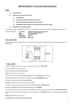
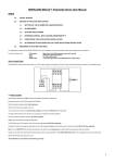
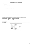
MINIMINDER USER MANUAL (AC & DC VERSIONS)
The unit is factory set to:Current run time
00000 hours (reset condition)
Grand total run time
00000 hours (reset condition)
Maintenance interval
08760 hours (or custom setup if specified)
Before setting up the unit for your particular application please carry out the following checks in order to familiarise yourself
with the programming and readout procedures.
1.0 START UP
Connect the brown and blue wires to the AC supply then:Switch on the power
GREEN LED ON
After 2 seconds
GREEN LED OFF
After a further 2 seconds
GREEN LED ON
The unit is functioning correctly.
2.0 STORED DATA READOUT
The unit stores the Current run time, The Grand total run time, the Programmed Maintenance Interval and the Alarm Output
mode setting in sequence. This data may be retrieved, at any time, using the red 2 pin programming plug. The value of
each stored digit is counted out (except leading zeros) by the green LED as a series of slow, easily countable, flashes.
When using the 2 pin programming plug, ensure that you are not statically charged and that the plug is gripped only by
the serrated handle.
Insert the red 2 pin plug into the programming socket
(white bar indicates position)
Switch on power to the unit
LED ‘BLINKS’ EVERY 0.8 SECONDS
Remove 2 pin plug
LED OFF
Reinsert 2 pin plug
LED ‘BLINKS’ EVERY 0.8 SECONDS
Current run time count out complete
stored data is zero (factory set)
Remove 2 pin plug
LED OFF
Reinsert 2 pin plug
LED ‘BLINKS’ EVERY 0.8 SECONDS
Grand total run time count out complete
stored data is zero (factory set)
Remove 2 pin plug
LED OFF
Reinsert 2 pin plug and count flashes
**0, 1, 2, 3, 4, 5, 6, 7, 8
2 second delay (highest digit)
0, 1, 2, 3, 4, 5, 6, 7
2 second delay
0, 1, 2, 3, 4, 5, 6
2 second delay
0
(lowest digit)
LED‘BLINKS’ EVERY 0.8 SECONDS
Programmed maintenance interval count out complete
stored data is 8760 hours (factory set)
Switch off power and remove 2 pin plug
Data readout finished
** Digital counting starts at 0 (zero) not 1
3.0 PROGRAMMING APPLICATION DATA
You can now set up the unit to suit your particular application by programming in the required maintenance interval
e.g. 02193 hours.
Switch on the power
GREEN LED ON
After 2 seconds
GREEN LED OFF
Issue 2
1
Immediately insert the red 2 pin plug
(white bar indicates position)
LED ‘BLINKS’ EVERY 0.8 SECONDS
PROGRAMMING MODE ENABLED
Remove 2 pin plug
LED OFF
programming started
(lowest to highest digit)
Reinsert 2 pin plug and count flashes
**0,1,2 then on 3
remove programming plug
LED OFF
3 programmed
Reinsert 2 pin plug and count flashes
0, 1, 2, 3, 4, 5, 6, 7, 8 then on 9
LED OFF
9 programmed
Reinsert 2 pin plug and count flashes
0, then on 1
LED OFF
1 programmed
Reinsert 2 pin plug and count flashes
0, 1 then on 2
LED OFF
2 programmed
Reinsert 2 pin plug and count flashes
on 0
remove programming plug
LED blinking
0 programmed
02193 hours programmed
Switch off
remove programming plug
remove programming plug
remove programming plug
Programming complete
** Digital counting starts at 0 (zero) not 1
3.1 CHECKING YOUR PROGRAMMING
It is always good practice to check any new data stored. Simply repeat Section 2.0 to count out:-
2 1 9 3
4.0 INSTALLATION
Mount the unit in a convenient location using 2 off M3 fixing screws. Connect the brown and blue wires to the switched side
of your machine’s/equipment’s main power switch to record the total time it has been switched on. Alternatively you can
connect it to the switched side of your machine’s/equipment’s start/stop button to record the total time it has been operating.
Note: Miniminder only updates its permanent time records every 6 minutes (0.1 hour) and therefore should not be
connected to a supply that is being continually switched on and off (e.g. every few minutes).
The green LED provides an ‘at a glance’ indication of the remaining maintenance interval:LED On continuous
On, blinking off (25mS @ 0.8 seconds)
0.4 seconds flashing @ 0.8 seconds
0.2 seconds flashing @ 0.4 seconds
blinking on (25mS @ 0.8 seconds)
3 flash burst every 2.4 seconds
> 80% remaining
> 60% remaining
> 40% remaining
> 20% remaining
< 20% remaining
INTERVAL EXPIRED
5.0 RESET CURRENT RUN TIME
The Current run time can be reset at any time (during normal operation) as follows:Check that the Miniminder unit is already powered on
LED indication present
Insert the red 2 pin plug and wait
LED off continuously
Remove red 2 pin plug
LED ON then after 2 seconds LED OFF
After a further 2 seconds
LED ON Current run time reset to zero
6.0 FACTORY RESET
The factory settings can be restored, if required, as follows:Carry out Section 3.1, programming zero for every entry
LED Blinking DO NOT SWITCH OFF THE POWER
Insert the red 2 pin plug
WAIT until LED FLASHING, restore enabled
Remove red 2 pin plug
LED ON, restoring
Wait one second
LED OFF, finished
Switch off power
FACTORY SETTINGS RESTORED
Issue 2
2
MINIMINDER-USB USER MANUAL (V6.9)
The unit is factory set to:Current run time
00000 hours (reset condition)
Grand total run time
00000 hours (reset condition)
Maintenance interval
08760 hours (or custom setup if specified)
Dual function output mode
0 Active on when maintenance interval expired, and on demand USB
Unit identifier
MM001
1.0 USB SERIAL DATA OUTPUT
Skip this section if the USB feature is not being used. MINIMINDER-USB provides an optocoupler isolated, serial data
output of the stored data via a serial to TTL adaptor cable. This adaptor utilises a Prolific PL2303HXD integrated circuit and
associated software drivers installed in the connected Windows computer.
1.1 WINDOWS DRIVERS
These can be installed by connecting the TE-C0320 adaptor to the pc whereupon Windows will automatically search the
computer and the Internet to locate and install the appropriate drivers.
Alternatively the drivers can be manually downloaded from the Prolific website. Simply click on the following link
www.prolific.com.tw/US/ShowProduct.aspx?p_id=225&pcid=41 to go directly to the drivers download page. Then click
on PL2303_Prolific_Driverinstaller_v1.11.0.zip. Click ‘Save as’ and save the .zip file to a destination of your choice. Go to
the location where you saved the .zip file, double click to open the .zip file and then click ‘Extract all files’, tick ‘show
extracted files when complete’ and then click Extract.
When the files have been extracted a new window will open showing the extracted files. Double click the
PL2303_Prolific_Driverinstaller_v1.11.0.exe file and then click Run (windows installation wizard activates). Follow the on
screen instructions to install the drivers.
Next, connect your TE-C0320 adaptor cable to a USB port and the drivers should now automatically install. Click the
Windows Start button and type in the search box ‘device manager’ and click on Device Manager. Expand the Ports (COM &
LPT) device to identify the virtual com port number assigned to the Prolific USB-to-Serial Comm Port e.g. COM3.
1.2 TERMINAL EMULATOR
Any terminal emulator can be used to link to the Virtual Com Port and display the serial data on screen and save to file for
easy transfer to Excel. One such emulator is Termite, a simple ‘message oriented’ screen display with logging file capability.
This can be downloaded from the Compuphase website www.compuphase.com/software_termite.htm.
Click the Termite version 3.1 – complete setup link (or latest version, if not version 3.1). Click ‘Save as’ and save the file
to a destination of your choice. Go to the location where you saved the file, double click the termite-3.1.exe file and click
Run. Follow the on screen instructions to install the program and then the terminal emulator will automatically open.
Click on the Settings button and set up the Termite Port configuration as follows, clicking OK when done:Port
e.g. COM3
(enter assigned Com Port as identified in section 1.1 above)
Baud rate
2400
Data bits
8
Stop bits
2
Parity
none
Flow control
none
To activate Termite’s very useful logging file feature click on the Settings button, and in the Plug-ins section tick the Log File
tick box. Double click on the words Log file to open the Logfile filter settings window. Click the J button and in this
window select a directory location and enter a .txt filename of your choice, then press Save. Click OK to close this window
and then click OK to close the Settings window. Termite will now save all received data into this logging file for easy
transfer to Excel. In due course, to access the data from your MINIMINDER, open the log file in Wordpad (not Notepad).
1.3 TEST YOUR COMMS SETUP
Test the installed drivers and terminal emulator software as follows:Connect the brown/blue (or red/black) wires to the AC (or DC) supply
Connect orange/black wires to adaptor green/black wires
Connect adaptor to pc
Start terminal emulator program
SCREEN DISPLAY SHOWS COMMS INITIALISED
Insert the red 2 pin plug into the programming socket, (white bar indicates position)
Issue 2
3
Switch on the power
SCREEN DISPLAY SHOWS [00] A NUL CHARACTER
Followed by
* MM001,00000.0,08760,00000.0, SE
(data at last service)
Followed by
* MM001,00000.0,08760,00000.0, OK
(data at previous demand)
Followed by
* MM001,00000.0,08760,00000.0, OK
(data at this demand)
Switch off power and remove red 2 pin plug
Disconnect all wiring
*Unit Identity, Current Run Time, Programmed Maintenance Interval, Grand Total Run Time, OK/EX/SE
2.0 START UP
Connect the brown/blue (or red/black) wires to the AC (or DC) supply then:Switch on the power
GREEN LED ON
After 2 seconds
GREEN LED OFF
After a further 2 seconds
GREEN LED ON
The unit is functioning correctly.
3.0 STORED DATA READOUT
The unit stores the Current Run Time, the Grand Total Run Time, the Programmed Maintenance Interval, the Dual Function
Output mode setting and the Unit Identifier in sequence. This data may be retrieved, at any time, using the red 2 pin
programming plug. The value of each stored digit is counted out (except leading zeros) by the green LED as a series of
slow, easily countable, flashes.
When using the 2 pin programming plug, ensure that you are not statically charged and that the plug is gripped only by
the serrated handle.
Insert the red 2 pin plug into the programming socket
(white bar indicates position)
Switch on power to the unit
LED ‘BLINKS’ EVERY 0.8 SECONDS
Remove 2 pin plug
LED OFF
Re-insert 2 pin plug
LED ‘BLINKS’ EVERY 0.8 SECONDS
Current run time count out complete
stored data is zero (factory set)
Remove 2 pin plug
LED OFF
Re-insert 2 pin plug
LED ‘BLINKS’ EVERY 0.8 SECONDS
Grand total run time count out complete
stored data is zero (factory set)
Remove 2 pin plug
LED OFF
Re-insert 2 pin plug and count flashes
**0, 1, 2, 3, 4, 5, 6, 7, 8
2 second delay (highest digit)
0, 1, 2, 3, 4, 5, 6, 7
2 second delay
0, 1, 2, 3, 4, 5, 6
2 second delay
0
(lowest digit)
LED‘BLINKS’ EVERY 0.8 SECONDS
Programmed maintenance interval count out complete
stored data is 8760 hours (factory set)
Remove 2 pin plug
LED OFF
Re-insert 2 pin plug and count flashes
0
LED‘BLINKS’ EVERY 0.8 SECONDS
Programmed dual function o/p mode count out complete
stored data is 0 (factory set)
Note: You can switch off now if you are not using the USB feature (Unit Identifier superfluous)
Remove 2 pin plug
Issue 2
LED OFF
4
Re-insert 2 pin plug and count flashes
0
2 second delay (highest digit)
0
2 second delay
0, 1
2 second delay (lowest digit)
LED OFF
Programmed unit identifier count out complete
stored data is 001 (factory set)
Data count out complete
Switch off power
** Digital counting starts at 0 (zero) not 1
4.0 SETTING UP YOUR APPLICATION
The MINIMINDER-USB can be used in Control/Alarm output only applications or Control/Alarm output (with on demand USB
serial data output) applications or automatic USB serial data output only applications.
4.1 CONTROL/ALARM ONLY APPLICATIONS
In these applications the Dual Function Output is permanently connected to the external control/alarm devices.
The figure below shows the connection of the orange and black wires in typical applications.
4.2 CONTROL/ALARM APPLICATIONS WITH ON DEMAND USB
Skip this section if the USB feature is not being used. In these applications a double pole changeover switch or similar
arrangement must be employed to completely disconnect the orange and black wires from any control/alarm devices (4.1)
and connect to the installed TE-C0320 USB adaptor. This configuration suits applications where the pc/laptop is only
connected on a periodic basis (i.e. once per day/week/month or service engineer visit).
The current stored data can then be transmitted to the connected laptop/pc/tablet as follows:Switch off the power to the MINIMINDER-USB
Insert red programming plug
Connect laptop to the USB adaptor and open terminal communications program
Switch on power
Stored data transferred to laptop (see section 1.3)
Switch off power, remove red programming plug, disconnect laptop
Reinstate control/alarm devices connection
4.3 AUTOMATIC USB ONLY APPLICATIONS
Skip this section if the USB feature is not being used. In these applications the dual function output is dedicated to USB
serial data output. This configuration suits applications where the pc/laptop is connected on a semi permanent basis (i.e. to
collect daily on/off usage pattern information).
The current stored data is transmitted whenever the MINIMINDER-USB power is switched on:MM001,00000.0,08760,00000.0, SE
MM001,00000.0,08760,00000.0, OK ON
Issue 2
5
and automatically every run time hour thereafter:MM001,00000.0,08760,00000.0, OK
Note OK replaced by EX when maintenance interval exceeded.
The TE-C0320 USB adaptor may be permanently connected to the dual function output or connected/disconnected as
required.
4.4 DUAL FUNCTION OUTPUT MODES
The dual function output can be programmed for the following operating modes:MODE 0 (factory set)
MODE 1
MODE 2
MODE 3
Output is active on when programmed maintenance interval expired, on demand USB
Output is active on when current run time OK, on demand USB
Output replicates green LED status (see Section 4.8), on demand USB
Power up and automatic timed serial send USB only, alarm/control function disabled
4.5 UNIT IDENTITY
MINIMINDER-USB can be programmed with a unit identifier MM000 to MM999 (Factory Set MM001).
4.6 PROGRAMMING APPLICATION DATA
You can now set up the unit to suit your particular application by programming in the required maintenance interval, the
dual function output mode and Unit Identifier e.g. 02193 hours, mode 1 (active on when current run time OK, on demand
USB), MM007.
Switch on the power
GREEN LED ON
After 2 seconds
GREEN LED OFF
Immediately insert the red 2 pin plug
(white bar indicates position)
LED ‘BLINKS’ EVERY 0.8 SECONDS
PROGRAMMING MODE ENABLED
Remove 2 pin plug
LED OFF
programming started
(lowest to highest digit)
Re-insert 2 pin plug and count flashes
**0, 1, 2 then on 3
remove programming plug
LED OFF
3 programmed
Re-insert 2 pin plug and count flashes
0, 1, 2, 3, 4, 5, 6, 7, 8 then on 9
LED OFF
9 programmed
Re-insert 2 pin plug and count flashes
0, then on 1
LED OFF
1 programmed
Re-insert 2 pin plug and count flashes
0, 1 then on 2
LED OFF
2 programmed
Re-insert 2 pin plug and count flashes
on 0
remove programming plug
LED blinking
0 programmed
02193 hours programmed
Re-insert 2 pin plug and count flashes
0 then on 1
remove programming plug
LED blinking
1
Output mode 1 programmed
remove programming plug
remove programming plug
remove programming plug
Note: You can switch off now if you are not using the USB feature (Unit Identifier superfluous)
Re-insert 2 pin plug and count flashes
0, 1, 2, 3, 4, 5, 6 then on 7
LED OFF
7 programmed
Re-insert 2 pin plug and count flashes
on 0
LED OFF
0 programmed
Re-insert 2 pin plug and count flashes
on 0
remove programming plug
LED blinking
0 programmed
007 identifier programmed
Switch off
remove programming plug
remove programming plug
Programming complete
** Digital counting starts at 0 (zero) not 1
Issue 2
6
4.7 CHECKING YOUR PROGRAMMING
It is always good practice to check any new data stored. Simply repeat Section 3.0 to count out:Programmed Maintenance Interval
2 1 9 3
Output Mode
1
Identifier
007
4.8 INSTALLATION
Mount the unit in a convenient location using 2 off M3 fixing screws. Connect the brown/blue wires (red/black for DC units)
to the switched side of your machine’s/equipment’s main (AC or DC) power switch to record the total time it has been
switched on. Alternatively you can connect it to the switched side of your machine’s/equipment’s start/stop button to record
the total time it has been operating.
Note: MINIMINDER only updates its permanent time records every 6 minutes (0.1 hour) and therefore should not be
connected to a supply that is being continually switched on and off (e.g. every few minutes).
The green LED provides an ‘at a glance’ indication of the remaining maintenance interval:LED On continuous
On, blinking off (25mS @ 0.8 seconds)
0.4 seconds flashing @ 0.8 seconds
0.2 seconds flashing @ 0.4 seconds
blinking on (25mS @ 0.8 seconds)
3 flash burst every 2.4 seconds
> 80% remaining
> 60% remaining
> 40% remaining
> 20% remaining
< 20% remaining
INTERVAL EXPIRED
4.9 ALARM/CONTROL DEVICE CONNECTION
Section 4.1 shows the connection of typical alarm/control devices to the dual function output orange and black wires. If the
on demand USB feature is to be used then a double pole changeover switch or similar arrangement must be employed to
completely disconnect the orange and black wires from the control/alarm devices (4.1) to allow connection to the TE-C0320
USB adaptor.
4.10 USB ADAPTOR CONNECTION
A number of alternative connection arrangements are possible to suit particular applications.
4.10.1 INTERNAL TE-C0320 ADAPTOR, INTERNAL CONNECTION (PC connected to internal cable)
This arrangement provides a ‘free’ pc connection cable with the machine/equipment. The USB adaptor is permanently
located with the machine/equipment.
4.10.2 INTERNAL TE-C0320 ADAPTOR, EXTERNAL CONNECTION (PC connected to bulkhead USB-B socket cable)
This arrangement provides a bulkhead mounted USB-B socket for pc connection. The USB adaptor is permanently located
with the machine/equipment. Drill a 27mm diameter hole at a convenient location on the machine bulkhead and install the
CHASSISCON1 B-A socket. Plug the USB adaptor into the rear socket.
4.10.3 EXTERNAL TE-C0320DIN ADAPTOR, EXTERNAL CONNECTION (PC connected to bulkhead DIN socket)
This arrangement provides a bulkhead mounted DIN socket for pc connection. The USB adaptor is not located with the
machine/equipment. Drill an 18mm diameter hole at a convenient location on the machine bulkhead and install the
CHASSISCON2 DIN socket/extension lead assembly. Connect the extension lead orange/black wires to the MINIMINDER
orange/black wires.
Issue 2
7
4.11 TESTING ON DEMAND USB APPLICATIONS (Dual Function Output Modes 0, 1, 2)
Section 1.3 details the serial data output to the connected pc.
4.12 TESTING ON AUTOMATIC USB APPLICATIONS (Dual Function Output Mode 3)
Section 4.3 details the serial data output to the connected pc.
4.13 TESTING ALARM/CONTROL OUTPUT CONNECTIONS
Correct operation of alarm/control devices connected to the MINIMINDER output connections (orange & black wires) can be
confirmed using the inbuilt diagnostic feature. Simply:Carry out Section 3.0
LED Off but DO NOT SWITCH OFF THE POWER
*** Remove red 2 pin plug
WAIT 2 SECONDS
Insert the red 2 pin plug, wait
LED on, Output active on
Remove red 2 pin plug
WAIT 2 SECONDS
Insert the red 2 pin plug, wait
LED off, Output inactive off
Remove red 2 pin plug
Return to start (***) and repeat as necessary
5.0 RESET CURRENT RUN TIME
The Current run time can be reset at any time (during normal operation) as follows:Check that the MINIMINDER unit is already powered on
LED indication present
Insert the red 2 pin plug and wait
LED off continuously
Remove red 2 pin plug
LED ON then after 2 seconds LED OFF
After a further 2 seconds
LED ON Current run time reset to zero
This operation would normally be carried out at the end of a service procedure. The run time data is automatically stored
as a machine time record of this service, for USB transfer (see sections 1.3 & 4.3).
6.0 FACTORY RESET
The factory default settings can be restored, if required, as follows:Carry out Section 4.6, programming zero for every entry
LED Blinking DO NOT SWITCH OFF THE POWER
Insert the red 2 pin plug
WAIT until LED FLASHING, restore enabled
Remove red 2 pin plug
LED ON, restoring
Wait one second
LED OFF, finished
Switch off power
FACTORY SETTINGS RESTORED
Eltime Controls: Hall Road, Maldon, Essex, CM9 4NF UK.
Eltime Controls is a division of Eltime Ltd.
© Eltime Ltd. MINIMINDER-USB User Manual 07/2015
Issue 2
8