1
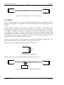
L-Switch™
EIA-709 Multi-port-Switch
&
EIA-709 2-port-Switch
User Manual
LOYTEC
L-Switch User Manual
3
LOYTEC
This page is intentionally left blank!
Version 4.4
LOYTEC
L-Switch User Manual
4
LOYTEC
Contact
LOYTEC
Stolzenthalergasse 24/3
A-1080 Vienna
AUSTRIA/EUROPE
[email protected]
http://www.loytec.com
Version 4.4
Document No. 88062508
LOYTEC MAKES AND YOU RECEIVE NO WARRANTIES OR CONDITIONS,
EXPRESS, IMPLIED, STATUTORY OR IN ANY COMMUNICATION WITH YOU, AND
LOYTEC SPECIFICALLY DISCLAIMS ANY IMPLIED WARRANTY OF
MERCHANTABILITY OR FITNESS FOR A PARTICULAR PURPOSE.
No part of this publication may be reproduced, stored in a retrieval system, or transmitted, in
any form or by any means, electronic, mechanical, photocopying, recording, or otherwise,
without the prior written permission of LOYTEC.
L-Chip™, LC7093™ and L-CORE™ are trademarks of LOYTEC.
LonTalk©, LonWorks© and Neuron©, LonMaker and LNS are trademarks of Echelon
Corporation registered in the United States and other countries.
Version 4.4
LOYTEC
L-Switch User Manual
5
LOYTEC
Contents
1
2
Introduction..........................................................................................................................9
1.1
Overview .......................................................................................................................9
1.2
Scope ...........................................................................................................................10
1.3
L-Switch vs. L-Switch XP...........................................................................................10
Enclosure and Installation..................................................................................................11
2.1
2.1.1
L-Switch multi-port ..............................................................................................11
2.1.2
L-Switch 2-port.....................................................................................................11
2.2
Mounting .....................................................................................................................12
2.3
DIP Switch Settings.....................................................................................................12
2.3.1
Regular L-Switch..................................................................................................13
2.3.2
L-Switch XP .........................................................................................................13
2.4
Power Supply...............................................................................................................13
2.5
Connecting Diagrams ..................................................................................................15
2.5.1
LS-13300C(B) (3-Port).........................................................................................15
2.5.2
LS-13333C(B) (5-Port).........................................................................................16
2.5.3
LS-11333C(B) (5-Port).........................................................................................16
2.5.4
LS-33300C(B) (3-Port).........................................................................................17
2.5.5
LS-33C(B) (2-Port)...............................................................................................17
2.5.6
LS-13C(B) (2-Port)...............................................................................................18
2.5.7
LS-11C(B) (2-Port)...............................................................................................18
2.5.8
LS-38C (2-Port) ....................................................................................................19
2.6
3
4
Enclosure .....................................................................................................................11
Wiring..........................................................................................................................19
Network Media ..................................................................................................................21
3.1
TP-1250 .......................................................................................................................21
3.2
FT-10 ...........................................................................................................................21
3.3
RS-485.........................................................................................................................22
3.4
PLT-22.........................................................................................................................23
Operating Modes................................................................................................................24
4.1
Message Forwarding Modes .......................................................................................24
4.1.1 Smart Switch Mode ..............................................................................................24
4.1.1.1 Domain Learning ...........................................................................................24
4.1.1.2 Subnet/Node Learning ...................................................................................24
Version 4.4
LOYTEC
L-Switch User Manual
4.1.1.3
4.1.1.4
4.1.1.5
5
7
8
LOYTEC
Group Learning ..............................................................................................25
Broadcast Address Learning ..........................................................................25
Unique Node ID Address Learning ...............................................................25
4.1.2
Repeater Mode......................................................................................................25
4.1.3
Configured Router Mode (L-Switch XP only) .....................................................26
4.2
Bit-Rate Auto-Detection .............................................................................................26
4.3
Network Buffers ..........................................................................................................27
User Interface.....................................................................................................................28
5.1
Status Button ...............................................................................................................28
5.2
LED Signals ................................................................................................................28
5.2.1
Status LED............................................................................................................28
5.2.2
Port LEDs .............................................................................................................28
5.3
6
6
Console........................................................................................................................29
5.3.1
Self Test ................................................................................................................29
5.3.2
L-Switch Configuration Menu (Main Menu) .......................................................30
5.3.3
System Configuration Menu.................................................................................31
5.3.4
EIA-709 Configuration Menu...............................................................................33
5.3.5
Reset configuration (load factory defaults) ..........................................................33
5.4
Network Diagnostics ...................................................................................................34
5.5
Resetting the switching tables .....................................................................................35
The L-Switch in a Network................................................................................................36
6.1
L-Switch and L-Switch XP as Smart Switch ..............................................................36
6.2
L-Switch XP as EIA-709 Router.................................................................................36
6.3
Network Variables.......................................................................................................37
6.4
Wink action .................................................................................................................38
Updating the L-Switch Firmware ......................................................................................39
7.1
Firmware Update via the Network ..............................................................................39
7.2
Firmware Update via the Console ...............................................................................39
Troubleshooting .................................................................................................................42
8.1
TP-1250 port does not work........................................................................................42
8.2
One or more port LEDs are flashing red .....................................................................42
8.3
All port LEDs are flashing red ....................................................................................43
8.4
LonMaker cannot commission node ...........................................................................43
8.5
All LEDs light up orange about every second ............................................................43
8.6
Technical Support........................................................................................................44
Version 4.4
LOYTEC
L-Switch User Manual
9
7
LOYTEC
Application Notes ..............................................................................................................45
10
L-Switch Firmware Versions..........................................................................................46
11
Specifications..................................................................................................................47
11.1
LS-xxxxxC and LS-xxC...........................................................................................47
11.2
LS-xxxxxCB and LS-xxCB .....................................................................................47
12
Revision History .............................................................................................................49
Version 4.4
LOYTEC
L-Switch User Manual
9
LOYTEC
1 Introduction
1.1 Overview
The L-Switch is a high performance fully plug-and-play network infrastructure component for
EIA-709 networks. It is the first device that allows building fully manageable EIA-709
networks. It is also a cost effective alternative to currently available EIA-709 routers. The
L-Switch provides up to five communication ports and it switches packets between these
ports. Its unique architecture very much supports structured wiring in EIA-709 networks by
reducing the number of necessary routing devices.
The Plug & Play installation capability of the L-Switch allows connection of the L-Switch to
the network without any further configuration. The smart switching software automatically
detects the bit-rates of the connected channels, learns the configuration of the network
(domains, subnet/node addresses, group addresses) and forwards the packets between the
different ports (see Section 4.1.1). Optionally, the L-Switch can be configured via the
network.
In addition to the Plug & Play switch mode newer versions of the L-Switch, which are labeled
L-Switch XP, can be operated as a standard configured EIA-709 router. In this operating
mode the L-Switch is compatible to any standard EIA-709 router and must be commissioned
using LonMaker or some other network management tool for EIA-709 networks.
As an additional feature, the L-Switch permanently collects statistic information from the
attached network channels (channel load, CRC errors, forwarding statistics, etc.). Using this
data the L-Switch software is able to detect problems on these channels (overload,
connections problems, etc.) and warns the system operator via LEDs (see Section 5.4). An
intuitive user interface allows fast and easy network troubleshooting without any additional
analysis tools and deep system knowledge.
The LSD Tool can be used for a more detailed view of the collected statistics data. See
Section 9 for more information on this powerful system diagnostics tool.
The L-Switch is used for:
♦ Isolation of local network traffic
♦ Structuring networks (structured wiring)
♦ Signal regeneration
♦ Noise suppression
♦ Extending channels in their physical dimension and/or number of nodes
♦ Connecting channels with different communication media types e.g. power-line and FT
♦ Network monitoring and network management
Version 4.4
LOYTEC
L-Switch User Manual
10
LOYTEC
1.2 Scope
This document covers L-Switch devices with firmware version 4.4. See Section 10 for
differences between the different L-Switch firmware versions.
1.3 L-Switch vs. L-Switch XP
The L-Switch comes in two versions: Newer versions of the L-Switch are labeled L-Switch
XP, while older versions are just labeled L-Switch (without XP). The main difference is, that
the L-Switch XP can be configured to operate as a standard EIA-709 router, which can be
commissioned using LonMaker or any other network management tool for EIA-709 networks.
The devices which do not have the XP label do not offer this operating mode. In this
document older versions of the L-Switch are referred to as regular L-Switch, wherever there
is a need to make a distinction from the new L-Switch XP.
Further, the L-Switch is available in two different housings: A multi-port version, which can
have up to 5 ports (see Figure 1) and a 2-port version in a smaller housing, which comes
always with 2 ports (see Figure 2).
This document covers all versions of the L-Switch. Differences between these versions are
pointed out in the corresponding sections. Please identify the L-Switch version you are using
before reading this manual.
Version 4.4
LOYTEC
L-Switch User Manual
11
LOYTEC
2 Enclosure and Installation
2.1 Enclosure
2.1.1 L-Switch multi-port
The L-Switch multi-port enclosure is 9 TE (1 TE = 17.5 mm) wide for DIN rail mounting,
following DIN 43 880 (see Figure 1).
60
157
DIP Switch
Order Number
off
on
Serial Number
Unique Node IDs
1234567
Console Connector
Status LED
Status Button
15
86
Port LEDs
1
2
3
4
5
6
7
8
9 10 11 12 13 14 15
Terminals
24 25 26
55
Figure 1: L-Switch multi-port enclosure (dimensions in mm)
2.1.2 L-Switch 2-port
The L-Switch 2-port enclosure is 6 TE (1 TE = 17.5 mm) wide for DIN rail mounting,
following DIN 43 880 (see Figure 2).
Version 4.4
LOYTEC
L-Switch User Manual
12
LOYTEC
60 0
105.0
DIP Switch
Order Number
off
on
Serial Number
Unique Node IDs
1234567
15
86
Port LEDs Console Connector Status LED Status Button
1
2
3
4
5
6
Terminals
15 16 17
55
Figure 2: L-Switch 2-port enclosure (dimensions in mm) product label
The product label on the right side of the L-Switch contains the following information (see
Figure 1):
♦ L-Switch order number with bar-code (Code 128, e.g. LS-13333C)
♦ Serial number with bar-code (Code 128)
♦ Unique node ID of each port (NIDx)
An additional label is also supplied with the L-Switch for documentation purposes.
2.2 Mounting
The device comes prepared for mounting on DIN rails following DIN EN 50 022.
The device can be mounted in any position. However, an installation place with proper
airflow must be selected to ensure that the L-Switch temperature does not exceed the
specified range (see Section 10).
2.3 DIP Switch Settings
The L-Switch uses 7 switches to select the mode of operation.
Version 4.4
LOYTEC
L-Switch User Manual
13
LOYTEC
Important: The regular L-Switch and the L-Switch XP use the DIP switches in different
ways to select the operating mode. Be sure to identify the correct DIP switch
setting for your L-Switch version!
2.3.1 Regular L-Switch
The DIP switch assignment for the L-Switch multi-port is shown in Table 1. For details see
Chapter 4.
DIP
Switch #
1
2
3
4
5
6
7
Function
Group learning On/Off
Subnet/Node learning
On/Off
Channel auto detection
On/Off
(RS-485 ports only)
Backbone arbitration
On/Off
(TP-1250 ports only)
Station ID Bit 0 (LSB)
Station ID Bit 1
Station ID Bit 2 (MSB)
Factory Default
Settings
ON
ON
ON
OFF
OFF
OFF
OFF
Table 1: DIP switch settings for L-Switch multi-port
2.3.2 L-Switch XP
The DIP switch assignment for the L-Switch XP is shown in Table 2. For details see Chapter
4.
DIP Switch #
1, 2
Function
ON, ON:
L-Switch switch mode
ON, OFF:
L-Switch repeater mode
OFF, ON:
L-Switch subnet learning
OFF, OFF: Configured EIA-709 router
Bit-rate auto detection On/Off
(RS-485 version only)
Must be OFF
Reserved
Reserved
Reserved
3
4
5
6
7
Factory Default
ON, ON
ON
OFF
OFF
OFF
OFF
Table 2: DIP switch settings for L-Switch XP
2.4 Power Supply
The L-Switch can either be DC or AC powered (Table 3 to Table 6).
Version 4.4
LOYTEC
L-Switch User Manual
14
Terminal
24
25, 26
Function
Main Earth Ground
Power Inputs
LOYTEC
Note
9-35 VDC or
9-24 VAC
± 10%
Table 3: Power Terminals for L-Switch multi-port LS-xxxxxC
Terminal
15
16, 17
Function
Main Earth Ground
Power Inputs
Note
9-35 VDC or
9-24 VAC
± 10%
Table 4: Power Terminals for L-Switch 2-port LS-xxC
Terminal
24
25, 26
Function
Main Earth Ground
Power Inputs
Note
12-35 VDC or
12-24 VAC
± 10%
Table 5: Power Terminals for L-Switch XP multi-port LS-xxxxxCB
Terminal
15
16, 17
Function
Main Earth Ground
Power Inputs
Note
12-35 VDC or
12-24 VAC
± 10%
Table 6: Power Terminals for L-Switch XP 2-port LS-xxCB
Important: Do not ground one of the power supply wires on terminal 26 (LS-xxxxxC and
LS-xxxxxCB) or terminal 17 (LS-xxC and LS-xxCB) as shown in Figure 4!
Figure 3: Attach the ferrite to the power cord
Attach the ferrite that comes with the L-Switch to the power cord as shown in Figure 3 (LSxxxxxC and LS-xxC only). Make sure the power cord passes the ferrite twice.
The following power supplies are recommended for use with the L-Switch:
Version 4.4
LOYTEC
L-Switch User Manual
15
LOYTEC
Manufacturer: IDEC IZUMI CORPORATION
Manufacturer part number: PS5R-A12
Description: Power Supply, 12V, 7.5W, UL 508, CSA C22.2 No.14, EN60950, 100-240VAC
LOYTEC order number: LS-PS7W
Note: Switched power supplies like the IDEC IZUMI PS5R-A12 might interfere with powerline communication. If you are using the LS-38C because your application requires
communication over the power-line we strongly recommend a linear power supply or
have the switched power supply tested against interference with power-line
communication signals. The IDEC power supply is not recommended for use with the
LS-38C.
2.5 Connecting Diagrams
The L-Switch provides screw terminals to connect to the network as well as to the power
supply. The screw terminals can be used for wires having a maximum thickness of 1.5
mm2/AWG12.
2.5.1 LS-13300C(B) (3-Port)
Terminal
Function
1-6
NC
7
Earth Ground
8, 9
EIA-709 A, B of FT-10 Channel Port 3
10
Earth Ground
11, 12
EIA-709 A, B of FT-10 Channel Port 2
13
Earth Ground
14, 15
EIA-709 A, B of TP-1250 Channel Port 1
24
Main Earth Ground
25, 26
Power Supply (do not connect 26 to ground)
Table 7: L-Switch Terminals LS-13300C and LS-13300CB
Version 4.4
LOYTEC
L-Switch User Manual
16
LOYTEC
2.5.2 LS-13333C(B) (5-Port)
Terminal
Function
1
Earth Ground
2, 3
EIA-709 A, B of FT-10 Channel Port 5
4
Earth Ground
5, 6
EIA-709 A, B of FT-10 Channel Port 4
7
Earth Ground
8, 9
EIA-709 A, B of FT-10 Channel Port 3
10
Earth Ground
11, 12
EIA-709 A, B of FT-10 Channel Port 2
13
Earth Ground
14, 15
EIA-709 A, B of TP-1250 Channel Port 1
24
Main Earth Ground
25, 26
Power Supply (do not connect 26 to ground)
Table 8: L-Switch Terminals LS-13333C and LS-13333CB
2.5.3 LS-11333C(B) (5-Port)
Terminal
Function
1
Earth Ground
2, 3
EIA-709 A, B of FT-10 Channel Port 5
4
Earth Ground
5, 6
EIA-709 A, B of FT-10 Channel Port 4
7
Earth Ground
8, 9
EIA-709 A, B of FT-10 Channel Port 3
10
Earth Ground
11, 12
EIA-709 A, B of TP-1250 Channel Port 2
13
Earth Ground
14, 15
EIA-709 A, B of TP-1250 Channel Port 1
24
Main Earth Ground
25, 26
Power Supply (do not connect 26 to ground)
Table 9: L-Switch Terminals LS-11333C and LS-11333CB
Version 4.4
LOYTEC
L-Switch User Manual
17
LOYTEC
2.5.4 LS-33300C(B) (3-Port)
Terminal
Function
1-6
NC
7
Earth Ground
8, 9
EIA-709 A, B of FT-10 Channel Port 3
10
Earth Ground
11, 12
EIA-709 A, B of FT-10 Channel Port 2
13
Earth Ground
14, 15
EIA-709 A, B of FT-10 Channel Port 1
24
Main Earth Ground
25, 26
Power Supply (do not connect 26 to ground)
Table 10: L-Switch Terminals LS-33300C and LS-33300CB
2.5.5 LS-33C(B) (2-Port)
Terminal
Function
1
Earth Ground
2, 3
EIA-709 A, B of FT-10 Channel Port 2
4
Earth Ground
5, 6
EIA-709 A, B of FT-10 Channel Port 1
15
Main Earth Ground
16, 17
Power Supply (do not connect 17 to ground)
Table 11: L-Switch Terminals LS-33C and LS-33CB
Version 4.4
LOYTEC
L-Switch User Manual
18
LOYTEC
2.5.6 LS-13C(B) (2-Port)
Terminal
Function
1
Earth Ground
2, 3
EIA-709 A, B of FT-10 Channel Port 2
4
Earth Ground
5, 6
EIA-709 A, B of TP-1250 Channel Port 1
15
Main Earth Ground
16, 17
Power Supply (do not connect 17 to ground)
Table 12: L-Switch Terminals LS-13C and LS-13CB
2.5.7 LS-11C(B) (2-Port)
Terminal
Function
1
Earth Ground
2, 3
EIA-709 A, B of TP-1250 Channel Port 2
4
Earth Ground
5, 6
EIA-709 A, B of TP-1250 Channel Port 1
15
Main Earth Ground
16, 17
Power Supply (do not connect 17 to ground)
Table 13: L-Switch Terminals LS-11C and LS-11CB
Version 4.4
LOYTEC
L-Switch User Manual
19
LOYTEC
2.5.8 LS-38C (2-Port)
Terminal
Function
1
PLT-Coupler GND (black) of
PLT-22 Channel Port 2
2
PLT-Coupler Signal (green) of
PLT-22 Channel Port 2
3
PLT-Coupler +12V (red) of
PLT-22 Channel Port 2
4
Earth Ground
5, 6
EIA-709 A, B of FT-10 Channel Port 1
24
Main Earth Ground
25, 26
Power Supply
Table 14: L-Switch Terminals LS-38C
2.6 Wiring
Every network segment connected to the L-Switch needs to be terminated according to the
rules found in the specification of the transceiver (see Chapter 3).
Important: All used and unused ports must be properly terminated. LOYTEC recommends
the use of the LOYTEC L-Term series network terminators (LT-13 or LT-33
respectively). For unused ports, it is recommended to use a 100 Ohm 0.25 W
resistor between terminals A and B as termination. Only the PLT-22 port can
be left un-terminated.
Important: All Earth ground terminals must be connected to the main Earth ground
terminal 24 (LS-xxxxxC and LS-xxxxxCB) or terminal 15 (LS-xxC and LSxxCB). When using shielded network cables only one side of the cable should
be connected to ground. Thus, the shield must be connected to earth ground
either at the L-Switch terminals or somewhere else in the network, but never at
more than one place (see Figure 4)!
Version 4.4
LOYTEC
L-Switch User Manual
20
LOYTEC
Ferrite
Port not in
use
100Ω
Power Supply
Figure 4: Connecting the L-Switch (LS-13333C)
Figure 4 shows an L-Switch where Port 5 is not used.
Version 4.4
LOYTEC
L-Switch User Manual
21
LOYTEC
3 Network Media
3.1 TP-1250
The TP-1250 uses transformers for galvanic isolation. The topology of a TP-1250 network is
a bus. Thus, both ends of the bus cable need to be terminated with a termination network as
shown in Figure 5.
102 Ω
340 Ω
59 Ω
330 nF
150 nF
Figure 5: TP-1250 Termination Network
If the collision-less backbone mode (recommended, default behavior) is disabled, the
L-Switch TP-1250 ports are fully compatible to the parameters specified by LonMark for this
channel (TP/XF-1250). If the collision-less backbone mode is enabled, proprietary channel
parameters are used. In this case no Neuron Chip based nodes or other nodes with standard
TP-1250 communication parameters are permitted on the same channel.
3.2 FT-10
The L-Switch FT-10 ports are fully compatible to the parameters specified by LonMark for
this channel. FT-10 ports can also be used on Link Power (LP-10) channels. However, the
L-Switch does not provide the power supply for Link Power channels.
When using the Free Topology Segment feature of the FT-10, only one termination (Figure 6)
is required and can be placed anywhere on the free topology segment.
100 µF, 50V
+
52,3 Ω
+
100 µF, 50V
Figure 6: FT-10 Free Topology Termination
In a double terminated bus topology, two terminations are required (Figure 7).
terminations need to be placed at each end of the bus.
Version 4.4
These
LOYTEC
L-Switch User Manual
22
LOYTEC
100 µF, 50V
100 µF, 50V
+
+
105 Ω
105 Ω
+
+
100 µF, 50V
100 µF, 50V
Figure 7: Termination in an FT-10 Bus Topology
3.3 RS-485
The L-Switch RS-485 ports are fully compatible with the parameters specified by TIA/EIA
RS-485 for this channel. A maximum of 32 L-Switch RS-485 ports can be connected to one
channel.
The RS-485 ports support bit-rates between 300 kbps and 2.5 Mbps. When using bit-rate
auto-detection (see Section 4.2) the L-Switch checks for the following bit-rates: 0.61 kbps,
1.221 kbps, 2.441 kbps, 4.883 kbps, 9.766 kbps, 19.531 kbps, 39.0625 kbps, 78.125 kbps,
156.25 kbps, 312.5 kbps, 625 kbps, 1,250 kbps and 2,500 kbps. Standard Neuron Chip
compatible channel parameters with a channel priority of 4, but no node priority are used with
these bit-rates. If bit-rate auto-detection is switched off, the channel parameters for the
LonMark TP-RS485-39 channel (39 kbps) are used.
RS-485 can only be used in a bus configuration and must be terminated on both ends. The
maximum stub length between the main bus and a single node is 0.3 m.
Figure 8 shows the termination required on both ends of the bus.
120 Ω
Figure 8: RS-485 Termination
RS-485 requires bus terminations on both ends of the bus (Figure 9).
120 Ω
120 Ω
0.3 m max.
Node
Figure 9: Termination in a RS-485 Bus Topology
Version 4.4
LOYTEC
L-Switch User Manual
23
LOYTEC
3.4 PLT-22
The L-Switch LS-38C is shipped with a PLT-Coupler module to be used with the Power-Line
port of the device. See Figure 10 on how to connect the PLT-Coupler module to the
L-Switch.
The PLT-Coupler module must be plugged directly into a wall outlet. Do not plug the PLTCoupler into a power strip or behind any lightning or surge protection filters, which might
affect power-line communication. Also check that a 120 VAC rated PLT-Coupler is used in
120 VAC systems (USA, Japan) and that a 230 VAC PLT-Coupler is used for 230 VAC
mains (Europe).
Do not short the outputs of the PLT-Coupler and follow the wiring diagram as shown in
Figure 10.
The LS-38C is configured for a 3.5Vpp transmit level with the CENELEC access protocol
enabled. For 7 Vpp transmit level and/or the CENELEC access protocol disabled please
contact LOYTEC for availability at [email protected].
bl gn rd
Ferrite
PLT
Coupler
Power Supply
Figure 10: Connecting the L-Switch to the Power-line Coupler (bl: black, gn: green, rd: red).
Important: To minimize the channel load on the power-line channel LOYTEC strongly
recommends operating the LS-38C as configured router only (see Section
4.1.3)!
Version 4.4
LOYTEC
L-Switch User Manual
24
LOYTEC
4 Operating Modes
4.1 Message Forwarding Modes
Depending on the DIP switch settings of DIP switch 1 and 2 the L-Switch supports 3 different
methods to route packets between the different EIA-709 ports. Both, the L-Switch and the
L-Switch XP support smart switch mode and repeater mode. The L-Switch XP in addition
supports the EIA-709 router mode.
Important: Whenever the forwarding mode of the L-Switch is changed using the DIP
switch a reset to factory defaults is recommended!
4.1.1 Smart Switch Mode
The L-Switch can be configured to act as a self-learning switch in an EIA-709 network. In
this operation mode the L-Switch decides based on the destination address of a message, to
which port(s) the message has to be forwarded or whether it has to be forwarded at all. Thus,
it isolates local network traffic (e.g. in case of heavy loaded networks). This is the default
operating mode for the L-Switch.
Figure 11 shows the proper DIP switch setting to put the L-Switch into learning switch mode.
This DIP switch setting is the factory default setting.
off
on
1234567
Figure 11: DIP switch setting for learning switch mode (factory default)
Important: This smart switch routing algorithm does not support any kind of network
loops!
Important: Whenever a network is reconfigured, it is recommended to clear the forwarding
tables in the L-Switch by pressing the status button for at least 20 seconds (see
Section 5.4).
4.1.1.1 Domain Learning
The L-Switch supports learning of up to 4 Domains.
Note: All messages, which are received on an unknown domain are forwarded to all ports!
4.1.1.2 Subnet/Node Learning
The subnet/node learning algorithm supports segmentation of the network traffic on a
subnet/node basis. Thus, the user does NOT need to take care of any subnets spanning
Version 4.4
LOYTEC
L-Switch User Manual
25
LOYTEC
multiple physical channels. Even when a node is moved from one channel to another, the
L-Switch keeps track and modifies its forwarding tables accordingly.
If needed the regular L-Switch allows switching off subnet node learning using DIP switch
number 2 (see Table 1).
Note: All messages with a destination subnet/node address not yet learned are forwarded to
all ports!
4.1.1.3 Group Learning
The L-Switch supports group learning. Groups can span multiple L-Switch ports.
If needed the regular L-Switch allows switching off group learning using DIP switch number
1 (see Table 1).
Note: Group learning only works for messages using acknowledged or request/response
service.
Note: All messages with a destination group address not yet learned are forwarded to all
ports!
4.1.1.4 Broadcast Address Learning
The L-Switch has no learning strategy for broadcast addresses.
As a result, all subnet or domain wide broadcasts are forwarded to all ports1.
4.1.1.5 Unique Node ID Address Learning
The L-Switch has no learning strategy for unique node ID addresses.
Node ID addressed messages are forwarded to all ports.
4.1.2 Repeater Mode
The L-Switch can be configured to operate in a repeater mode, where all messages are
forwarded to all ports regardless of the address format.
To put the L-Switch into repeater mode the following steps need to be performed:
1. Set the L-Switch into repeater mode (switch OFF subnet/node learning and group
learning) by setting DIP switches 1 and 2 in the appropriate position (see Figure 12
and Figure 13).
2. The forwarding tables must be reset by pressing the status button for at least 20
seconds (see Section 5.4).
1
Firmware versions 2.0 and up allow to disable subnet broadcast flooding. Please contact LOYTEC support if
you need to enable this feature!
Version 4.4
LOYTEC
L-Switch User Manual
26
LOYTEC
Figure 12 and Figure 13 show the proper DIP switch settings for repeater mode on the two
different L-Switch versions, assuming all other DIP switches remain in the factory default
position.
off
on
1234567
Figure 12: DIP switch settings to enable repeater mode for an regular L-Switch
off
on
1234567
Figure 13: DIP switch settings to enable repeater mode for an L-Switch XP
4.1.3 Configured Router Mode (L-Switch XP only)
In this operating mode the L-Switch acts like a standard EIA-709 compatible router, which
can be configured with standard network management tools like LonMaker or NL-220. This
operating mode is compatible with any other standard EIA-709 router. It is only possible on
the L-Switch XP.
Figure 14 shows the proper DIP-switch settings for EIA-709 compatible router mode,
assuming all other DIP-switches remain in the factory default position.
off
on
1234567
Figure 14: OFF-OFF: DIP-switch settings for configured router mode.
Standard EIA-709 routers allow 4 different operating modes, which must be configured via a
network management tool (e.g. LonMaker): configured router, learning router, bridge and
repeater. Since the learning algorithm in the smart switch operating mode (see Section 4.1.1)
is superior to the learning router mode of a EIA-709 router, the learning router mode is not
supported by the L-Switch.
Further, note that the repeater mode of the EIA-709 router differs from the L-Switch repeater
mode (see Section 4.1.2). While the L-Switch repeater mode is transparent and does not
require any additional configuration, the repeater mode of the EIA-709 router must be
configured using a network management tool and thus requires commissioning.
4.2 Bit-Rate Auto-Detection
The L-Switch supports bit-rate auto-detection on RS-485 channels. The factory default DIP
switch setting enables bit-rate auto-detection on all RS-485 ports. Figure 15 shows the DIP
Version 4.4
LOYTEC
L-Switch User Manual
27
LOYTEC
switch settings to disable bit-rate auto-detection, assuming all other DIP switches remain in
the factory default position.
off
on
1234567
Figure 15: DIP switch settings to disable bit-rate auto-detection
Alternatively the bit-rate auto-detection can be enabled/disabled on a per port basis via the
console menu (see Section 5.3.2). Further the console menu allows restarting the bit-rate
auto-detection on selected ports.
While the port is auto-detecting the corresponding port LED is flashing orange.
4.3 Network Buffers
The L-Switch can handle packets from the network with a maximum length of 256 bytes.
There is no explicit limit in the network buffer counts.
Version 4.4
LOYTEC
L-Switch User Manual
28
LOYTEC
5 User Interface
5.1 Status Button
The L-Switch is equipped with a status button (see Figure 1). When pressing the status button
shortly during normal operation of the L-Switch, it sends a “Service Pin Message” on every
port. Note that every L-Switch port has its own unique node ID (“Neuron ID”).
Pressing the status button longer than 2 seconds will allow you to select the port to sends out
the “Service Pin Message” message: The port LED of the currently selected port will light up
orange. After 2 seconds the next available port will be selected. When the status button is
released the “Service Pin Message” is sent out on the currently selected port.
If the L-Switch is operated in smart switch mode (see Section 4.1.1) or repeater mode (see
Section 4.1.2) pressing the status button for more than 20 seconds resets the switching tables
(see Section 5.4).
5.2 LED Signals
5.2.1 Status LED
The L-Switch is equipped with a two-color status LED (green and red, see Figure 1).
When power is applied to the L-Switch, the status LED is green. During boot-up the status
LED is used to signal error conditions (red).
5.2.2 Port LEDs
Each port on the L-Switch has a three color LED (green, red and orange, see Figure 1). Table
15 shows the port different LED patterns and their meaning.
Behavior
Description
GREEN flashing fast
GREEN flashing at 1 Hz
Traffic
Port unconfigured
RED permanent
RED flashing fast
Port damaged
Traffic with high amount of errors
(see Section 5.4)
Firmware image corrupt
Please upload new firmware
Port disabled
RED flashing at 1 Hz
(all ports)
ORANGE permanent
ORANGE flashing fast
ORANGE flashing at 1
Hz
ORANGE permanent
(all ports)
Version 4.4
Traffic on port configured as management
port
Bit-rate auto-detection
Comment
L-Switch XP operated as EIA-709
router (see Section 4.1.3) only
e.g. using LSD Tool
(see Section 9)
e.g. using LSD Tool
(see Section 9)
RS-485 ports only
Status button pressed for more than 20
seconds
Switching tables will be reset once button is
released
LOYTEC
L-Switch User Manual
29
LOYTEC
Table 15: Port LED patterns
5.3 Console
The L-Switch is equipped with a serial interface to
♦ display the results of the self test
♦ allow advanced configuration via a console menu
♦ upgrade the L-Switch firmware
To use the serial interface the console connector (see Figure 1 and Figure 2) of the L-Switch
can be connected to the RS-232 port of a PC. Now, the PC can communicate with the
L-Switch using a standard terminal program with the communication settings set to 38,400
bps / 8 data bits / no parity / 1 stop bit.
For the LS-xxxxxC and LS-xxC series a 1:1 female-male serial cable is required to connect
the L-Switch to the RS-232 port of a PC, while on the LS-xxxxxCB and LS-xxCB series a
standard null-modem-cable with full handshaking must be used.
5.3.1 Self Test
Whenever the L-Switch comes out of reset it performs a self test. If the self test passed
successfully, all port LEDs successively turn green for 0.5 seconds. If a failure occurs during
self test, the status LED is flashing red and the L-Switch is reset.
The console output of a successful boot sequence on an L-Switch with 5 ports on the console
reads as follows:
LOYTEC electronics GmbH
www.loytec.com
Testing
Testing
Testing
Testing
Testing
Testing
Board ID (0F)
RAM
boot loader
fallback image
primary image
Flash
Passed
Passed
Passed
Passed
Passed
Passed
Loading primary image
Passed
Starting application
Passed
Port
Port
Port
Port
Port
Passed
Passed
Passed
Passed
Passed
1
2
3
4
5
detected
detected
detected
detected
detected
(XF/TP-1250)
(FT-10)
(FT-10)
(FT-10)
(FT-10)
L-SWITCH(c)
LOYTEC electronics GmbH
Thu Dec 22 15:58:11 2005 - V4.4.0
System has passed self-test and is active ...
Figure 16: Console messages during the boot phase
Version 4.4
LOYTEC
L-Switch User Manual
30
LOYTEC
The duration of a successful boot sequence of an L-Switch with 5 ports is typically 10
seconds.
5.3.2 L-Switch Configuration Menu (Main Menu)
After booting the L-Switch displays the following console menu:
L-Switch Configuration Menu
===========================
[1]
[2]
[3]
[4]
[8]
[0]
Show device information
Serial firmware upgrade
System configuration
EIA-709 configuration
Reset configuration (factory defaults)
Reset device
Please choose:
Figure 17: L-Switch main menu
The menu items are described below:
1 - Show device information
This menu item shows information on the L-Switch and the current firmware. The output
should look like what is shown in Figure 18.
Product information
===================
Product code:
Firmware:
Version:
Build date:
Serial number:
Free memory:
System temp:
Supply volt:
LS-13333C
Primary image
3.1.0
Apr 9 2004
000104-80000000FC80
898K,59K
25.9C
23.6V
Unique node IDs
===============
Port
Port
Port
Port
Port
1
2
3
4
5
(EIA709):
(EIA709):
(EIA709):
(EIA709):
(EIA709):
80
80
80
80
80
00
00
00
00
00
00
00
00
00
00
00
00
00
00
00
FC
FC
FC
FC
FC
80
8F
7F
8D
8C
Figure 18: Device information
2 - Update firmware
This menu item allows updating the L-Switch firmware via the serial interface (console). See
Section 7.2 for detailed instructions.
Note: If you select this option accidentally you can return to the main menu by sending a
break signal. In case your terminal program does not offer an option to send a break
signal the device has to be reset to return to the main menu.
Version 4.4
LOYTEC
L-Switch User Manual
31
LOYTEC
3 - System configuration
Select this menu item to change system configuration settings. See Section 5.3.3 for details.
4 - EIA-709 configuration
Select this menu item to change the EIA-709 configuration settings. See Section 5.3.4 for
details.
8 - Reset configuration (factory defaults)
This menu item resets the L-Switch to factory defaults. See Section 5.5 for details on how to
load factory defaults by pressing the status button and Section 5.3.5 on how to load factory
defaults through the console menu.
0 - Reset L-Switch
This menu item resets the L-Switch.
Note: Not all firmware versions provide a console menu. See Section 10 on which firmware
versions support this feature.
5.3.3 System Configuration Menu
The system configuration menu allows setting the principal operating modes of the L-Switch.
System Configuration Menu
=========================
[1]
[2]
[3]
[4]
[6]
[7]
[8]
Set date/time (GMT)
Router mode
Subnet/node learning
Group learning
Block zero length domain
Block unknown domains
Factory reset w. status button
[q]
[x]
Quit without saving
Exit and save
:
:
:
:
:
:
:
2002-10-29 08:37:15
Smart Switch Mode
subnet/node (DIP)
enabled (DIP)
disabled
enabled
enabled
Please choose:
Figure 19: System Configuration Menu
1 - Set date/time
If present this menu option allows setting the battery powered on-board real-time clock.
Older hardware versions do not come with a real-time clock. In this case this menu option is
not present.
2 - Router Mode (L-Switch XP only)
The router mode menu allows setting the principal operating mode of the L-Switch routing
core. Normally the operating mode of the routing core is set with the DIP switches 1 and 2
but can be overridden in this menu. This option is present on the L-Switch XP only.
Version 4.4
LOYTEC
L-Switch User Manual
32
LOYTEC
Set router mode
===============
[1]
[2]
[3]
Enable Configured Router Mode
Enable Smart Switch Mode
Set router configuration according to DIP switch
Please choose:
Figure 20 Router mode configuration menu
3 - Subnet/node learning
This menu option allows selecting the subnet/node learning mode (see Figure 21).
Set subnet/node learning mode
=============================
[1]
[2]
[3]
[4]
Subnet/node learning
Subnet learning
Disable
Set router configuration according to DIP switch
Please choose:
Figure 21 Selecting subnet/node learning mode
If subnet/node learning is selected the L-Switch will learn based on subnet/node addresses
(see Section 4.1.1.2). Subnet broadcasts are flooded. This mode is plug&play.
If subnet learning is selected the L-Switch will learn based on subnets. Subnet broadcasts are
only forwarded to ports, which contain nodes with that subnet. Subnet learning should be
enabled if group overloading is used in the case that more than 256 group addresses are
needed. Subnet learning is not plug&play. Please use LonMaker, NL-220, or other network
management tools to ensure that one subnet address is only used behind one L-Switch port.
This can be achieved by using our L-Switch LonMaker shapes or by placing phantom routers
in e.g. NL-220. Please contact LOYTEC support if you think you need this feature!
If the mode is changed via the console menu, it cannot changed via the corresponding DIP
switch anymore (see Section 2.3). Choose “[4] Set router configuration according to DIP
switch”, to return control to the DIP switch.
4 - Group learning
This menu option allows enabling or disabling learning of group addresses (see Section
4.1.1.3).
6 - Block zero length domain
Please contact LOYTEC support if you think you might need to block zero length domain!
7 - Block unknown domains
The L-Switch will learn up to four domains. If your network contains more than four
domains please contact LOYTEC support for advice!
Version 4.4
LOYTEC
L-Switch User Manual
33
LOYTEC
8 - Factory reset w. status button
In case the L-Switch is in the mode repeater or smart switch, pressing the status button longer
than 20 seconds resets the switching tables (see Section 5.1). This function can be disabled
using this menu option.
5.3.4 EIA-709 Configuration Menu
This menu allows changing the EIA-709 transceiver configuration, enabling the collision-less
backbone mode for TP-1250 transceivers, and enabling bit-rate auto-detection for RS-485
transceivers.
EIA709 Configuration Menu
=========================
[1]
Port
Port
Port
Port
Port
1:
2:
3:
4:
5:
XF/TP-1250 (1250 kBit)
FT-10
FT-10
FT-10
FT-10
[q]
[x]
Quit without saving
Exit and save
Please choose:
Figure 22 EIA-709 configuration menu.
1 to 5 - Change transceiver configuration for Port 1 - 5
This menu item allows setting the default transceiver configuration for port 1 to 5 if there are
different possible transceiver configurations.
For TP-1250 transceivers it is possible to set the transceiver settings to collision-less
backbone mode. Please contact LOYTEC if you think you might need this feature!
For RS-485 transceivers it is possible to manually set the bit-rate or choose bit-rate autodetection. If auto-detection is enabled the detected bit-rate is shown. See Section 4.2 for an
in-depth discussion of this feature.
Please contact LOYTEC support (see Section 8.5) if you want to change the default
transceiver configuration (e.g. PLT-22 in CENLEC or NON-CENELEC mode).
9 - Bit-rate auto-detection configuration source (only if RS-485 port is present)
This menu item allows to set what decision element should be used to enable or disable the
bit-rate auto-detection. If [1] DIP Switch is selected the value set on the DIP switch (see
Table 1 and Table 2) is used to enable or disable the bit-rate auto-detection. If [2] Software is
selected the setting made with Option 1 - 5 is used to enable or disable the bit-rate autodetection.
5.3.5 Reset configuration (load factory defaults)
This menu item allows resetting the device into its factory default state. The following menu
appears.
Version 4.4
LOYTEC
L-Switch User Manual
34
LOYTEC
Reset Configuration Menu
========================
[1]
[2]
Reset everything to factory defaults
Reset switch configuration to factory defaults
[q]
Back to main menu
Please choose:
Figure 23 Reset to factory defaults menu.
1 - Reset everything to factory defaults
Pressing “1” resets the complete device to factory defaults (including error log etc.).
2 - Reset switch configuration to factory defaults
Pressing “2” performs a reset identical to pressing the status button longer than 20 seconds
(see Section 5.5). Use this menu item if you are moving EIA-709 network nodes between
different EIA-709 channels.
5.4 Network Diagnostics
The L-Switch provides simple network diagnostics via its port LEDs:
1) If the port LED does not light up at all this port is not connected to any network
segment or the connected network segment currently shows no traffic.
2) If the port LED is flashing green the state of the network segment connected to this
port is ok.
3) If the port LED is flashing red a potential problem persists on the network segment
connected to this port. This state is referred to as overload conditions.
A port overload condition occurs if
♦ the average bandwidth utilization of this port was higher than 70% or
♦ the collisions rate was higher than 5% or
♦ more than 15% CRC errors have occurred on a port with a power-line transceiver or more
than 5% on a port with a transceiver other than power-line or
♦ the L-Switch was not able to process all available messages.
For a deeper analysis of the reason of the overload condition it is recommended to use a
protocol analyzer (e.g. LOYTEC’s LPA) or a similar tool. The exact reason of the overload
condition can also be determined with the LSD Tool (see Section 9).
Version 4.4
LOYTEC
L-Switch User Manual
35
LOYTEC
5.5 Resetting the switching tables
If the L-Switch is in smart switch mode (see Section 4.1.1) or repeater mode (see Section
4.1.2) the status button needs to be pressed for at least 20 seconds, in order to reset the
switching tables. Resetting the switching tables means:
♦ Clearing the group forwarding, the subnet/node forwarding and the router domain table.
♦ Clearing the L-Switch status and statistic data.
♦ Resetting the L-Switch back to unconfigured state.
All this is done when the button is released. Afterwards a reset is performed to let the
changes take effect. Once the button is held down for more than 20 seconds all port LEDs are
switched to orange and stay orange until the button is released and the L-Switch is reset. This
indicates that the switching tables were reset.
Alternatively to holding down the status button the switching tables can be reset by selecting
the menu item “Reset to factory defaults” in the console menu (see Section 5.3.2).
Important: If the L-Switch is operated in smart switch mode (see Section4.1.1 ) and is
moved from one location to another or if major changes to the configuration of
the network are made, it is recommended to reset the L-Switch configuration to
factory defaults.
Important: Wait at least 30 seconds after power-up of the L-Switch before pressing the
Status Button to ensure that the L-Switch has booted properly!
Important: If the L-Switch is manually configured it is recommended to disable the option
to reset the L-Switch back to factory defaults via the status button to prevent
users from accidentally clearing the configuration! This can be done via the
console using the corresponding menu option in the system configuration
submenu (see Section 5.3.3)!
Version 4.4
LOYTEC
L-Switch User Manual
36
LOYTEC
6 The L-Switch in a Network
The L-Switch is based on LOYTEC’s powerful L-Core™ and L-Chip™ technology. It is
designed to be very robust and reliable in high bandwidth applications.
6.1 L-Switch and L-Switch XP as Smart Switch
In this operation mode the L-Switch behaves completely transparent in a network. To put it
simple: It installs like a repeater, but works like a router.
Installing and operating the L-Switch and L-Switch XP is plug and play when using the
factory default settings, which have
♦ Subnet/node learning enabled,
♦ Group learning enabled,
♦ Bit-rate auto detection enabled, and
♦ Collision-less backbone mode for TP-1250 ports disabled.
After connecting the network cables, the L-Switch can be powered up and it will start its
switching application.
When using a standard binding tool (e.g. LonMaker) bindings between nodes connected to
different ports can be done without considering the L-Switch. Further, an L-Switch can be
added anywhere to an already configured network without reconfiguring the nodes in the
network.
Optionally the L-Switch XP can be configured as a repeater. If configured as repeater this
does not have any impact on the routing algorithm of the L-Switch in smart switch mode.
In case the L-Switch has to be visible in an LNS base binding tool (e.g. LonMaker) LOYTEC
provides LonMaker shapes for the different L-Switch models (e.g. for documentation
purposes). Please refer to application note AN006E “L-Switch and LNS” (see Section 9) for
details.
The smart switch mode is the default operation mode for all L-Switch models.
6.2 L-Switch XP as EIA-709 Router
The L-Switch XP is designed to be compatible with standard EIA-709 routers, if operated as
EIA-709 router. Thus, it requires commissioning via a network management tool (e.g.
LonMaker) like any standard EIA-709 router to be fully functional.
Note: This operation mode is only available on models labeled L-Switch XP.
Version 4.4
LOYTEC
L-Switch User Manual
37
LOYTEC
Note: When shipped the L-Switch XP comes configured in smart switch mode. To use it as
EIA-709 compatible router changing the DIP-switches is required (see Section 2.3.2).
The L-Switch 2-Port can be installed with any network management tool like any other
standard EIA-709 router.
The L-Switch XP multi-port versions (3 to 5 ports) contain multiple standard EIA-709 routers
– one for each port – and one internal TP-1250 backbone. The internal TP-1250 is neither
visible nor accessible from the outside. Figure 24 shows an example for a 5-Port L-Switch
(LS-13333C).
Router
TP-1250
Router
FT-10
Router
FT-10
Router
FT-10
FT-10
Router
Internal TP-1250 Backbone
Figure 24: Internal structure of a 5-Port L-Switch in EIA-709 router mode.
Each router must be commissioned separately. The port LEDs of unconfigured routers are
flashing green with a frequency of 1 Hz (once per second).
Pressing the status button longer than 2 seconds will allow you to select the port to sends out
the “Service Pin Message” message: The port LED of the currently selected port will light up
orange. After 2 seconds the next available port will be selected. When the status button is
released the “Service Pin Message” is sent out on the currently selected port/router.
If an LNS based installation tool (e.g. LonMaker) is used, detailed instructions can be found
in application note AN006E “L-Switch and LNS” (see Section 9).
6.3 Network Variables
The L-Switch provides the current values of the on-board temperature sensor, the input
voltage on the power supply, the uptime, and the channel status via network variables on all
ports. Table 16 shows the corresponding network variables with their names, network
variable indices, maximum update rate, and the SNVT types.
Purpose
Version 4.4
Name
Index
SNVT Type
Min. Update
Interval [ms]
LOYTEC
L-Switch User Manual
38
LOYTEC
Purpose
Name
Index
SNVT Type
Current value of internal temperature
sensor (LM76)
Current value of the input voltage on the
power supply
Uptime of L-Switch (if RTC is present,
otherwise nvUptime.day is set to
SNVT_ELAPSED_TM_DAY_INVALID
)
Overload condition of L-Switch ports (bit
0 to 7 correspond to ports 1 to 8, a one on
this bit signals a overload condition on the
corresponding port)
nvoSystemTemp
0
SNVT_temp (#39)
Min. Update
Interval [ms]
2000
nvoSupplyVolt
1
SNVT_volt (#44)
2000
nvoUptime
2
SNVT_elapsed_tm
(#87)
Polled
nvoOverload
3
SNVT_state (#83)
2000
Table 16: Output network variables provided by the L-Switch
Note: These network variables are for monitoring purposes only. It’s not recommended to
bind these network variables to any nodes!
6.4 Wink action
When receiving a wink network management message all the port LEDs light up orange one
after the other back and forth three times (“scanner light”). At the end of this cycle the port
LED on which the wink command was received lights up three times.
Note: Not all firmware versions support the wink command. See Section 10 on which
firmware versions support this feature.
Version 4.4
LOYTEC
L-Switch User Manual
39
LOYTEC
7 Updating the L-Switch Firmware
The L-Switch firmware supports remote upgrade over the network and the serial console.
To guarantee that the L-Switch cannot be destroyed due to a failed firmware update the
L-Switch firmware consists of two images:
1. Fall-back image
2. L-Switch application image
The fall-back image is write protected in flash memory and provides everything needed to
talk to the L-Switch platform over the network. The L-Switch application image is designed
to be updated over the network whenever there is a need to do so.
The fall-back image makes sure that the L-Switch comes up in a status where the maintenance
software can at least talk to the L-Switch platform and can download a new L-Switch
application image.
When the L-Switch boots up with the fall-back image, all port LEDs are flashing red. In this
state it does not forward any messages.
Note: All configuration settings and all forwarding tables will be lost, when the firmware is
updated.
7.1 Firmware Update via the Network
Basically firmware downloads can be performed on every L-Switch port. However, since the
L-Switch is not based on a Neuron Chip a new firmware image cannot be downloaded with a
standard tool. Rather, a designated tool, the LSD Tool (see Section 9), must be used. See the
LSD Tool documentation for details on how to download a new L-Switch firmware via the
network.
7.2 Firmware Update via the Console
To download the firmware via the console the L-Switch must be connected to the RS-232 port
of a PC via its console interface as described in Section 5.3. You will need the LOYTEC
serial upgrade tool (LSU Tool), which can be downloaded from our homepage at
www.loytec.com.
Please make sure that the L-Switch console shows the main menu otherwise navigate to the
main menu or simply reset the L-Switch.
Double click on the *.dlc file that comes with the new firmware package. This should start
the LSU Tool and load the firmware image referenced in the dlc file. Please note that the dlc
file and the dl file must be stored in the same folder. The start window of the LSU tool is
shown in Figure 25.
Version 4.4
LOYTEC
L-Switch User Manual
40
LOYTEC
Figure 25 LSU Serial Upgrade Tool in idle mode.
If the L-Switch is not connected to COM1 you can change the port to COM1, COM2, COM3,
or COM4. Make sure that the product shown under “Product” matches the device you are
upgrading. Note that Figure 25 and Figure 26 do not necessarily show the proper product.
Press “Download” to start the download. A progress bar as shown in Figure 26 can be seen.
Figure 26 Progress bar during firmware download.
If the upgrade is successful the following window appears (Figure 27).
Figure 27 Successful firmware upgrade.
Double check that the new firmware is executed by selecting 1 and pressing Enter in the
console window. This will bring up the device information, which shows the current
firmware version.
Important: Upgrading the firmware results in all configuration data being lost! If any
user specific configuration was done via the LSD tool or the console menu this
Version 4.4
LOYTEC
L-Switch User Manual
41
LOYTEC
configuration has to be manually restored! If the L-Switch XP is operated in
configured router mode (see Section 4.1.3) it has to be re-commissioned!
Note: Not all firmware versions support a firmware update via the console. See Section 10
on which firmware versions support this feature.
Version 4.4
LOYTEC
L-Switch User Manual
42
LOYTEC
8 Troubleshooting
8.1 TP-1250 port does not work
Problem
Messages are not forwarded to or from the TP-1250 port(s). All other ports work properly.
Explanation
This problem might be due to mixing collision-less backbone mode and standard backbone
mode devices on one channel.
Solution
If the TP-1250 channel is used in collision-less backbone mode make sure all devices on the
network have collision-less backbone mode enabled, only L-Switch devices are connected to
this backbone and every L-Switch has a unique station ID set.
If the TP-1250 channel is used in standard backbone mode make sure that all L-Switch
devices have the collision-less backbone mode disabled.
8.2 One or more port LEDs are flashing red
Problem
One or more port LEDs are flashing red whenever there is traffic on the channel (instead of
green).
Explanation
The L-Switch has built-in network analysis functionality (see Section 5.4): Whenever it
detects a potential problem on one port, the corresponding activity LED will change its color
to red.
Solution
Most likely this behavior is due to a wiring problem. Check the wiring and termination of the
network connected to the affected port. If this does not solve your problem use a protocol
analyzer (e.g. LOYTEC’s LPA) and/or a network diagnostics tool (e.g. LOYTEC’s LSD Tool
or Echelon’s Nodeutil) to find the source of the problem.
Version 4.4
LOYTEC
L-Switch User Manual
43
LOYTEC
8.3 All port LEDs are flashing red
Problem
All port LEDs are flashing red at a rate of approx. once per second and the L-Switch does not
forward any messages.
Explanation
Somehow the primary image was destroyed and the fall-back image was booted (see Section
7). This image does not support forwarding of messages. It only allows downloading a new
firmware.
Solution
If this problem occurs because a firmware update was attempted (and failed somehow),
simply retry downloading the new firmware image.
If no firmware update was attempted, please contact LOYTEC support (see Section 8.6).
8.4 LonMaker cannot commission node
Problem
When adding a new node to a LonMaker project, LonMaker receives the service ping
message from that node, but is unable to commission it.
Explanation
This problem might be due to badly configured TP-1250 port.
Solution
See Section 8.1.
8.5 All LEDs light up orange about every second
Problem
All LEDs of my L-Switch (port & status LEDs) light up orange every second or so and it does
not forward any messages.
Explanation
Probably the power supply is too weak and the L-Switch reboots again and again.
Solution
Try to use a power supply following the specifications in the user manual.
Version 4.4
LOYTEC
L-Switch User Manual
44
LOYTEC
If the problem persists contact LOYTEC support (see Section 8.6).
8.6 Technical Support
LOYTEC offers free telephone and e-mail support for our L-Switch product series. If none of
the above descriptions solves your specific problem please contact us at the following
address:
LOYTEC electronics GmbH
Stolzenthalergasse 24/3
A-1080 Vienna
Austria / Europe
email:
web:
tel:
fax:
[email protected]
http://www.loytec.com
+43/1/40 20 805 0
+43/1/40 20 805 99
or
LOYTEC Americas Inc.
583 Union Chapel Road
Cedar Creek, TX 78612
USA
Email: [email protected]
web: http://www.loytec-americas.com
tel:
+1/512/332 2445
fax: +1/512/332 2445
Version 4.4
LOYTEC
L-Switch User Manual
45
LOYTEC
9 Application Notes
Please refer to the application notes listed in Table 17 for further information on using the
L-Switch in different application scenarios.
Application Note
AN002E - LSD Tool
Topic
How to use the enhanced statistic features of the L-Switch
with the LOYTEC system diagnostics tool (LSD tool)
AN006E - L-Switch and LNS
How to use the L-Switch with LonMaker and other
network management tools
AN004E - Backbone Mode
Further information on how to best utilize the high-speed
collision-less backbone mode of the L-Switch
AN005E - L-Switch with L-IP Backbone How to best utilize the L-Switch together with L-IPs
Table 17: L-Switch related application notes.
Version 4.4
LOYTEC
L-Switch User Manual
46
LOYTEC
10 L-Switch Firmware Versions
1.0
1.2 Final 1
2.0
3.0/3.1
4.2
Table 18 shows the most important features available only in certain firmware versions
depending on the firmware version. The L-Switch XP can be used with firmware versions 3.0
and up.
Console Menu
(configuration & firmware update)
-
√
√
√
√
Aging mechanism
-
√
√
√
√
Execute Wink NM command
-
√
√
√
√
Management port
-
√
√
√
√
Password protection
-
√
√
√
√
Full LSD 2.0 support
-
-
√
√
√
L-Switch XP support
-
-
-
√
√
Firmware Version/
Features
Commission in smart switch mode
√
Table 18: Available features depending on firmware version
Version 4.4
LOYTEC
L-Switch User Manual
47
LOYTEC
11 Specifications
11.1 LS-xxxxxC and LS-xxC
Operating Voltage.................................................... 9-35 V DC or 9-24 V AC ±10%
Power Consumption................................................. typ. 3 W
In rush current.......................................................... up to 1100 mA @ 24 VAC
Operating Temperature (ambient) ........................... 0°C to + 50°C
Storage Temperature................................................ -10°C to +85°C
Humidity (non condensing) operating ..................... 10 to 90% RH @ 50°C
Humidity (non condensing) storage......................... 90% RH @ 50°C
Enclosure ................................................................. Installation enclosure 9 TE (L-Switch
Multi-port) resp. 6 TE (L-Switch 2-Port),
DIN 43 880
Environmental Protection ........................................ IP 40 (enclosure); IP 20 (screw terminals)
Installation ............................................................... DIN rail mounting (EN 50 022) or wall
mounting
11.2 LS-xxxxxCB and LS-xxCB
Operating Voltage.................................................... 12-35 V DC or 12-24 V AC ±10%
Power Consumption................................................. typ. 3 W
In rush current.......................................................... up to 1100 mA @ 24 VAC
Operating Temperature (ambient) ........................... 0°C to + 50°C
Storage Temperature................................................ -10°C to +85°C
Humidity (non condensing) operating ..................... 10 to 90% RH @ 50°C
Humidity (non condensing) storage......................... 90% RH @ 50°C
Enclosure ................................................................. Installation enclosure 9 TE (L-Switch
Multi-port) resp. 6 TE (L-Switch 2-Port),
DIN 43 880
Environmental Protection ........................................ IP 40 (enclosure); IP 20 (screw terminals)
Version 4.4
LOYTEC
L-Switch User Manual
48
LOYTEC
Installation ............................................................... DIN rail mounting (EN 50 022) or wall
mounting
Version 4.4
LOYTEC
L-Switch User Manual
49
LOYTEC
12 Revision History
Date
31-12-01
12-02-02
Version
1.0
1.1
Author
JB
JB
10-06-02
1.2
JB
2.0
DL, JB
2.0
3.0
3.1
4.4
DL, JB
JB
JB
JB
15-09-03
23-01-04
28-04-04
07-02-06
Version 4.4
Description
Initial revision V1.0
Updated supply voltage range from 9-22 V AC to 9-24 V AC
(production lot 2)
Added installation instructions on ferrite
Updated L-Switch product label
Added recommended power supplies
Added connecting diagrams for LS-33300C and LS-33000C
Added description of console menu
Updated information on network diagnostics
Added description of Wink command
Added information on firmware update
Added information on LSD Tool
Added application note on L-Switch LonMaker shapes
Updated application note on L-Switch backbone mode
Added application note on using L-Switch devices with EIA-709/IP
Routers
Added firmware feature list
Updated cover sheet
Updates for Firmware version 2.0 (specifically Console Menu,
Network Variables, and Firmware Update)
Moved applications notes into separate documents
Added documentation of L-Switch 2-port version
Release version 2.0
Release version 3.0
Release version 3.1
Updated for Firmware version 4.4
Updated for LS-xxxxxCB and LS-xxCB
LOYTEC