1
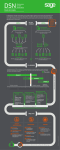
COLOR VIDEO DOOR PHONE
USER MANUAL
Thank you for purchasing our products.
The company is not responsible for any safety accidents caused by abnormal
operation of the product.
Please carefully read this User's Guide(in particular, precautions for safety) before
using this product.
Index
Warning and Caution
1
The function and name of each part
3
Features and main function
4
Package contents
5
System layout
5
Wiring diagram
7
Installation method
9
Cable specification
10
Operation guide
11
Incoming call answer
11
Monitor doorbells or CCTV cameras
12
Broadcast function
12
Internal call among monitors
12
Talking volume/Brightness/Contrast/Color adjust
13
“Don’t disturb ” function
13
Monitor listening
13
Capture images
14
Manual video record
14
DVR function
15
Auto leaving message
15
Family audio message
16
Change attention message for automatic answering function
16
Alarm clock and electronic calendar
17
Transfer
COVER outdoor panel’s call to the telephone/mobile
17
System main menu
18
Multimedia
19
Shortcuts
22
System setting
23
System setting menu
23
Parameters of picture capturing/video recording/DVR
28
Specification
29
Version 1.0
Warning and caution
Make sure to follow the instructions to prevent any danger or property losses.
It indicates prohibition.
Warning
Death or serious
injury is expected.
It indicates disassembly.
It indicates prohibition of contact.
It indicates dos and don’ts.
It indicates that the plug should be pulled out from
the socket.
warning
NO
Do not put the plug in the
socket simultaneously.
It may generate abnormal
heat or cause a fire.
NO
Do not use water, thinner or
a detergent used to wash oil
products when you wash the
exterior.
Make sure to wash it by using
a dry cloth to prevent any
breakdown or electric shock.
NO
NO
Do not connect to other
products while in use.
It may cause breakdown.
Do not forcibly bend the cord
or put a heavy object on the
product.
It may cause a fire.
NO
Do not install the product in a
humid place.
It may cause an electric
shock or a fire.
NO
Do not forcibly pull out the
cord from the socket.
If the cord is damaged, it
may cause a fire or an
electric shock.
NO
Do not put the plug in the
socket with a wet hand.
It may cause an electric
shock.
Page1
Do not disassemble, repair
Do not use AC circuit breaker.
or modify the product.
It may cause an electric shock.
It may cause a fire, an electric
shock or an injury due to
malfunction of the product.
It indicates prohibition.
Caution
A injury or property
losses are expected.
It indicates disassembly.
It indicates prohibition of contact.
It indicates dos and don’ts.
It indicates that the plug should be pulled out from
the socket.
CAUTION
The socket holes
are lager than
usual.
NO
If the socket holes are larger
than normal, do not put the
plug.
It may cause an electric shock
or a fire.
NO
Make sure that dust or
foreign substances are not
gathered on the product.
NO
Make sure to prevent foreign
substances from entering
the product.
It may cause a breakdown.
NO
Do not put a heavy object on
the product.
It may cause a breakdown.
Install the product in a flat and
stable place.
Otherwise, it may not function
properly.
Do not disassemble or give an
impact to the product.
Pull the plug if the product is
not used for a long time.
Avoid direct rays of the sun
or heating devices at a time
of installation.
If the product generates
strange sound, make sure to
pull the plug immediately
and contact service center.
Page2
The function and name of each part
3
4
2
5
6
7
1
8
10 11
No.
Page 3
Item
Function description
1
Speaker
2
LCD
3
Indicator
Indicate the state of the system
4
Back key
Back to/Hang up
5
Menu key
Enter system settings
6
Unlock key
7
Answer key
Answer/Call transfer
8
Monitor key
Monitoring
9
Microphone
10
TF card slot
11
Power switch
Power on/off
9
Features and main function
MODEL LIST
1.Features
7" color touch screen, high definition.
Voice/color/contrast/brightness adjustable
Maximum support 2 door panels + 4 monitors
Support TF card(up to 32GB)
OSD menu with various settings
Multi-language interface
8 polyphonic call-melodies
Comfortable mechanical keys
Surface-mounted
2.Main function
Real-time monitoring to doorbell or CCTV camera
Auto taking pictures when someone presses door panel
Answer machine function(auto leaving video message)
Manual video recording and picture taking function
Simple DVR function with motion detection
Leaving audio message for families
Multimedia function: photo frame, music playing
Door panel call transfer to other monitors
Make internal call to other monitors
Monitor listening to other monitors
Broadcast function
“Don’t disturb” function
Lock control
Call transfer (Only available for the version with PSTN interface)
Page 4
Package contents
Us er
Monitor
2* M4* 20
fixing screws
ma un
al
User manual
Wall bracket
2x5 pin connector
(red/blue/yellow/
white/brown)
4 pin connector
(red/blue/yellow/
white)
2*Expansion bolt
Desiccant
4 pin connector
(white/blue/
white/blue)
System layout
1.Connecting 2 door stations
The system can maximum support 1 master monitor ,2 door stations ,3 sub
monitors and 8 CCTV cameras.
Master Monitor
Sub Monitor
Sub Monitor
Sub Monitor
Door panel1
CCTV1
CCTV1
CCTV1
CCTV1
CCTV2
CCTV2
CCTV2
CCTV2
Door panel 2
Page 5
2.The port 2 connect to CCTV camera
The system can maximum support 1 master monitor ,1 door panel ,3 sub
monitors and 9 CCTV cameras .
Master Monitor
Sub Monitor
Sub Monitor
Sub Monitor
Door Panel1
CCTV1
CCTV1
CCTV1
CCTV1
CCTV2
CCTV2
CCTV2
CCTV2
CCTV3
Note: Based on the actual usage ,please refer to “ P25 system menu” to set
the port state.
Page 6
Wiring diagram
Solution1
Master monitor
(ROOM1)
TEL-A
TEL-B
P4
PSTN
(optional)
P3
AD-1
CCTV1
CCVT1
GND
GND
DATA
CCTV2
CCVT2
VD-1
GND
a
P2
AD
GND
PWR
VD
PWRLOCK-
electronic lock 2
P1
AD2
GND
PWR2
VD2
KEY2
AD1
GND
AD
GND
PWR1
VD1
PWR
b
VD
KEY1
Door panel 1
Door panel 2
electronic lock 1
TEL-A
TEL-B
P4
(optional)
P3
AD-1
CCTV1
CCVT1
GND
GND
DATA
CCTV2
CCVT2
VD-1
GND
P2
Sub monitor
(ROOM2)
P1
AD1
GND
AD2
GND
PWR1
VD1
PWR2
VD2
KEY2
KEY1
TEL-A
TEL-B
P4
(optional)
P3
AD-1
CCTV1
CCVT1
DATA
CCTV2
CCVT2
Sub monitor
(ROOM3)
GND
GND
VD-1
GND
P2
P1
AD1
GND
AD2
GND
PWR1
VD1
PWR2
VD2
KEY2
KEY1
TEL-A
TEL-B
P4
(optional)
P3
AD-1
CCTV1
CCVT1
GND
GND
DATA
CCTV2
CCVT2
VD-1
GND
Sub monitor
(ROOM4)
P2
P1
AD2
GND
PWR2
VD2
KEY2
Page 7
AD1
GND
PWR1
VD1
KEY1
Wiring diagram
Solution2
TEL-A
TEL-B
P4
PSTN
(optional)
P3
AD-1
CCTV1
CCVT1
DATA
CCTV2
CCVT2
Master monitor
(ROOM1)
GND
GND
VD-1
GND
P2
P1
AD1
GND
AD2
GND
AD
GND
PWR
VD
PWR1
VD1
PWR2
CCVT3
VD2
KEY2
KEY1
Door panel 1
TEL-A
TEL-B
P4
(optional)
P3
AD-1
CCTV1
CCVT1
GND
GND
DATA
CCTV2
CCVT2
VD-1
GND
P2
P1
AD1
GND
AD2
GND
Sub monitor
(ROOM2)
PWR1
VD1
PWR2
VD2
KEY2
KEY1
TEL-A
TEL-B
P4
(optional)
P3
AD-1
CCTV1
CCVT1
GND
GND
DATA
CCTV2
CCVT2
VD-1
GND
P2
Sub monitor
(ROOM3)
P1
AD1
GND
AD2
GND
PWR1
VD1
PWR2
VD2
KEY2
AD:Audio
VD:Video
PWR:Power
GND:Ground
DATE:Communication
CCTV:CCTV camera
KEY1
TEL-A
TEL-B
P4
(optional)
P3
AD-1
CCTV1
CCVT1
GND
GND
DATA
CCTV2
CCVT2
VD-1
GND
P2
Sub monitor
(ROOM4)
P1
AD2
GND
PWR2
VD2
KEY2
AD1
GND
PWR1
VD1
KEY1
Note: (a)Door panel unlock wiring: electronic lock 2+external power supply.
(b)Indoor monitor unlock wiring: electronic 1+bold black cable part.
Page 8
Installation
method
SINGLE MONITOR INSTALLATION
1.Refer to relevant wiring diagram for the system you have chosen and ensure you
have the correct cable.
2.Determine Monitor positions and heights:
-suggest to install at 1.5~1.6Meters;
-suggest distance between indoor monitor and doorbell is at least 350 mm;
3.Ensure no power supply connection before installation finished
4.Take off the bracket from the back of the monitor.
5.Install the bracket on the wall with expansion bolts and screws.
6.Connect cables as per the wiring diagram indicated.
7.Fix the monitor onto the bracket.
8.Connect power when doorbell is installed.
150cm
Page 9
Cable
Specification
Cable
specification
Our system has 2 solutions to unlock the door: Unlock signal from doorbell or unlock
signal from monitor.(The cable shield wire needs to be grounded)
When signal from the doorbell,cable specification is:
Distance between monitor and door station is less than 30 meters,shielded
RVVP4x0.3mm2 cable is available;
indoor monitor
1
2
3
4
Red
Blue
Yellow
white
AD1
GND
PWR1
VD1
KEY1
1
2
Red
Blue
3
4
Yellow
White
AD
GND
PWR
VD
Green
PWR- Brown
LOCK-
-
12V
++
-
electronic lock
2
outdoor panel
Distance exceed 30 meters,please choose SYV-75-3 coaxial cable for video with
another shielded 2*0.5mm2 cable or professional cable
SYV-75-3+RVVP2*0.5 mm2 ( recommend);
indoor monitor
Red
Blue
Yellow
White
AD1
GND
PWR1
VD1
KEY1
1
1
2
2
3
3
Red
Blue
Yellow
White
AD
GND
PWR
Green 12V +
PWRLOCK- Brown
-
+
-
electronic lock
VD
outdoor panel
When signal is from monitor,cable specification is:
Distance between monitor and door station is less than 30 meters,shielded
6*0.5mm2 cable is available;
AD1
GND
indoor monitor
PWR1
VD1
KEY1
Red
Blue
Yellow
White
Brown
Red
Blue
Green
AD
GND
PWR
VD
Yellow
White
Brown +
Green
outdoor panel
electronic lock
-
Distance exceed 30 meters,please choose professional cable SYV-75-3+RVVP
4*0.5 mm2 (recommend).
Red
Red
AD1
GND
indoor monitor
Blue
Green
GND
Yellow
Yellow
VD1
White
White
KEY1
Brown
PWR1
AD
Blue
Brown
Green
PWR
outdoor panel
VD
+
electronic lock
-
Page 10
Operation guide
1. Type of actions
The system support five kinds of action types:
1.1.Click: Enter. In multimedia manager interface, click anywhere of blank
place will show/hide the related operation menu.
1.2.Left slide: Left slide on the bottom of the screen can return to the last
menu/View last picture.
1.3.Right slide: Hide the menu in multimedia interface/View next picture.
1.4.Up slide: In system settings, up slide to next page.
1.5.Down slide: In system settings, down slide to last page.
2. operation interface
When at call, answering or monitoring state, the below menu will show on the
right of the screen, click the icon can make the related operation.
Icon description
Answer
Hang up
Call/Call
transfer
Monitor
Video
Function Image
switching adjustcapturing recording
ment
Unlock
Incoming call answer
When a visitor presses doorbell, the screen will show “INCOMING CALL”,
Press
Page 11
to talk with the visitor.
At ringing/ answering state, press
, then DOOR UNLOCKED will show on
the screen. If there is another call incoming during conversation, SOMEONE
IS VISITING DOOR 2 will display, press
At answering state, press
can switch to another visiting.
can transfer the call to other monitors.
Monitor doorbells/CCTV cameras
At standby status, press
button to monitor Doorbell 1, press
button
again, change the viewing screen to another video channel. When monitoring
the doorbell, press
press
button, you can talk with the visitor in front of the door,
again to unlock the door.
Broadcast function
At standby status , press and hold the
button for 2 seconds, the screen
will show BROADCAST REQUEST, the monitor in other rooms will show
BROADCASTING . Now you can make broadcast to all other monitors .Press
to end broadcast request.
Internal call among monitors
At standby status. press
button to call other indoor monitor, If you have
more than 2 monitors connected in the system, please click the target monitor
on the screen to make the call, press
button can hang up the call.
Page 12
Talking volume/brightness/contrast/color/display mode
adjustment
At monitoring, calling, intercom status, click the icon
on the screen, click
or
to adjust the volume. Click
, volume icon will show
again, you can enter
the BRIGHT/COLOR /CONT adjust screen.
“Don’t disturb” function
At standby status, click touch screen or press
main menu, click
be
button to enter system
icon to turn on this function, then the icon will change to
, and the LED indicator will flickers. it means “Don’t disturb” mode is
active. At such state, the monitor will not chime when someone calls to it.
Click
again, the “Don’t disturb” mode will be disabled. And the LED
indicator will stop flicker. Also you can use SYSTEM SETTINGS menu to turn
“DO NOT DISTURB” function on or off.
Note: If this function enabled , the monitor will be mute when receiving intercom, broadcast request too, and the buttons will keep light at the same time.
Monitor listening
At standby state, long press
button to start the monitor listening function,
If you have more than 2 indoor monitors ,there would be option rooms for
choosing on screen, click target room to confirm.
Page 13
Note:
a. At monitor listening state, monitoring part can hear the sound from be
monitored room, but be monitored intercom can not hear the voice from the
monitoring one.
b. When there are more than 2 monitors in the system, monitor listening
function is available only when “BE MONITORED” option in system settings is
enabled. Please check the system setting menu to see how to enable the
monitor listening function.
Capture images
At ringing or monitoring status, press
button to take a picture. If enable “Auto
taking picture” function in system setting menu, the system will automatically take
and save pictures when someone presses door panel. Please refer to “P24 system
setting menu” for detail operation.
Manual video record
At monitoring or answering state, press
function, press
button to start video recording
button again to stop recording.
Note: For operation of viewing and managing video files, please refer to P20.
Remark:
All of the above operations by buttons can be done on the touch screen too.
Page14
DVR function
a) SD card capacity must be over 2G, 8G memory card is recommended.
b)To enter the System setting menu to start the DVR function, detailed setting
please refer to "P24 System Setup Menu";
c)When the start time and the end time are set as the same time, the DVR
function will be active once screen waiting time ends. And it will keep working
24 hours per day
d) To get high quality video, we kindly suggest setup 640* 480 resolution.
e) DVR function only record images, and do not record sound.
Auto leaving message
This function allows your visitors to leave a video message for you while nobody is at
home. You should set “ANSWER MODE ” to be “AUTO ANSWER” or enable the
“AUTO LEAVING MESSAGE” option in the SYSTEM SETTINGS menu before
leaving home . When a visitor presses the door panel, after the chime time ends (5
seconds), visitor will hear a voice from the door panel “Hello, no one is at home at the
moment, please leave a message after the tone” and the indoor monitor will start
video recoding after the tone. Video recording duration time is 20 seconds. After
recording, the door panel will prompts“The recording is over, thank you”.
Note: For operation of viewing and managing the video messages, please refer to P20.
Family audio message
Page 15
Recording an audio message
At standby status, click touch screen or press
main menu, click
button to enter the system
icon to start recording, and the icon will turn red. After
recording the message, click
icon again to stop recording. After recording,
there will be a number on the right top corner of
icon.
Note: For operations of checking and managing messages and more
operation, please refer to P21.
Change attention message for “Auto leaving message”/
“Auto answer” function
When “Auto leaving message” / “AUTO ANSWER” is enabled, if nobody
answers after chime time ends, the visit will hear a voice attention message:
“Hello, no one is at home at the moment, please leave a message after the
tone”. If the user wants to change this attention message( BEGINNING
TONE) into their own sound, please take the following steps:
Go to main menu and record one audio message, then click
menu to enter
the following menu. Choose the audio file you want to set as beginning tone,
click
to enter “CONFIG ATTENTION TONE” menu. Change the “TONE
TYPE” to be “USER TONE”, then change the “PLAY TYPE” to be “BEGINNING
TONE”. Also you can adjust the attention tone volume. After setting, click
“ACT” to save it. Same operation to change the ENDING TONE.
Alarm clock and electronic calendar
Page16
1.Go to “ALARM CLOCK SETTINGS” in the “SYSTEM SETTINGS”, and
enable one alarm clock.
2.When clock is alarming, you can turn off the alarm by clicking the chime icon
at the left bottom corner of the screen.
3.At the screen of below Figure 1, click the alarm clock (The left bottom
corner) or the display time (The right bottom corner), you can set the alarm
clock or calendar in the shortcut way.
4.Please refer to P26 for detailed settings.
Figure 1
Transfer outdoor panel’s call to telephone/mobile
(Only available for the version with PSTN interface)
1)Go to the system setting menu, set the "ANSWER MODE" to be "CALL
TRANSFER". Then enter PHONE NUMBER SETTINGS menu and enter phone
number which the call will be transferred to. Please refer to "P26 System
settings menu."
2) If no one answers during CHIME TIME, the call will be transferred to the set
telephone. “TRANSFERRING TO TELE” will display on the monitor's screen
while transferring.
3)After picking up the call, the user will hear the chimes from the door panel.
a) Click “##” on the phone to talk with the visitor.
b) Click “**” on the phone to hang up the call.
c) Click “00" on the phone to unlock the door.
Page17
System main menu
At standby status, press
button or click the screen to enter system main
menu as Figure 2. Click the white icon can do the related settings/operations.
12/3/2013
12/3/2013
12:00
12:00
PHOTO
VIDEO
DVR
MULTIMEDIA
PHOTO
VIDEO
DVR
MULTIMEDIA
MUTE
SETTING
WAVE
RECORD
WATCH
CALL
BROARDCAST
MONITOR
Figure 2
1) Multimedia menu
Pictures
Functions
Re view/d elete captured images.
Notes
If there are new/unread images,
there will b e a number o n the
right top corner o f the ico n .
If there are new/unread video s,
Re view/d elete reco red vid eos.
there will b e a number o n the
right top corner o f the ico n.
Re view/d elete reco rded DVR
files.
View/delete the pictures stored
When you view imag es in the
in TF card .
TF card, click
Listen/delete the music files
then e very five seconds will auto
stored in TF card .
play next pictures.
View/delete the reco rd ed audio
If there are new/unread aud io s,
files.
there will b e a number o n the
And can change prompts voice.
right top corner o f the ico n.
or
,
Page18
1. View files
button to enter system main menu. If you have
At standby state, press
unread files, there will be a number on the right top corner of the multimedia
icon. and this number is quantity of unread files. Click the icon can go to the
following menu to check the unread files. On the end of each file name there
is a status instruction “?”or “√” When the state is "?", This means the file is
unread file. When the status is "√" , it means that the file has been viewed/
checked.
1.1 View captured images
Figure 3
Click
icon to view image files, click the file’s name then you can see image
as Figure 3. Click the
or
to switch to another image. After that, the
image will automatically switch in every 5 seconds. If you want to exit , click
can return to the last menu.
Page 19
1.2 Review video files
Figure 4
Return
Click
Last
video
Speed
down
Play/
Pause
Speed
up
Volume
decrease
Volume
increase
Next
video
to go to video files list, click a video file to enter above Figure 4. Click
the related icon can do the related operations. Left slide on the bottom of the
screen can return to last menu. Speed range can be 1 ~ 32 X mode.
1.3 View DVR files
Click
icon to go to DVR files list. The operations are the same as the
above review video files.
1.4 View multimedia files
Click
icon to enter review multimedia files list. You can view pictures and
play music same as the above operatioins(Review images).
Page 20
a) View images
same as the above operation “1.1 Review images”
Note: When there is no TF card inserted ,you can review the pictures in the
internal flash. If a TF card is inserted , you can view the pictures saved in the
TF card.
b) Play music(see below image Figure 5)
Figure 5
Last
music
Play/
Pause
Volume
decrease
Volume
increase
Delete
Next
music
1.5 View family leaving message
Click
, icon to enter message files list, click the file you want to listen.
And the below menu will appear. Click anywhere of blank place can hide/show
the menu. Left slide on the bottom of the screen can return to the last menu.
Last
music
Page 21
Play/
Pause
Volume
decrease
Volume
increase
Delete
Return
Next
music
1.6 Delete single file or folder
If you want to delete a file or folder, you can select the single file or folder in the
list, then Click
icon to delete the selected file or folder, and the screen
will show “ARE YOU SURE TO DELETE THE FILE ?” then click DELETE
to confirm.
2) Shortcuts
Pictures
Item
Back button
Watch
Function description
Enter calender screen/Exit/Return
Enter monitoring function, short-press to
switch channels
Call
Enter intercom function
broadcast
Enter broadcast function
Monitor
Enter monitoring listening function
Record
Enter record function
Mute
Enter mute function
Page 22
3) System setting
Pictures
Item
Function description
System setup Enter the system setting menu
System setting menu
No.
Se tting ite ms
Options
Note
10S/15S/20S/25 S/30
1-1
CHIM E TIME
S/35S /40S/45S
Ch im e duration time
/50S/55S /60S
1-2
CHIM E
10~1 00%
VOLUME
DOOR1
CHIM E
TYPE
DOOR2
1-3
CHIM E TYPE
SETTING
CHIM E
TYPE
00 -07
INTERCOM CHIM E
TYPE
RING E TONE
Ring tone will repea t when the
REPEAT
option is
1-4
NO DISTURB
The indo or monitor will be mute
wh en someon e presses
doo rbells/make intern al
call/broadcast.
Page 23
SYSTEM SETTINGS
No.
Setting ite ms
1-5
BE MONITORED
Options
Note
No icon nam es displayed on
1-6
the screen
ICON NAME
The icon names will display
on the screen
Do not capturing im ages
DISABLE
autom atically
Automatically capturing 1
1
1-7
image
AUTO CAPTURE
QUANTITY
Automatically capturing 2
2
images
Automatically capturing 3
3
1-8
COPY FILE TO SD
CANCEL
CARD
COPY
images
DVR ENABLE
MOTION
DETECTION
SENSITIVITY
1-9
DVR SETTING
BEGIN TIME
DVR starts wo rking.
END TIME
DVR end s working.
FRAME RATE
RESOLUTION
RECORD LOCATION
SCREEN SAVER TIME
The DVR will start wo rking at
1-9-1
DVR ENALBE
the BEGIN TIME.
Page 24
SYSTEM SETTINGS
No.
Se tting ite ms
Options
MOTION
1-9 -2
DETECTION
LOW
SENSITIVITY
NORMARL
Note
It means whether the motion
detection is start or sensitivity
HIGH
1-9 -3
BEGIN TIME
HOUR:M INUTER
1-9 -4
END TIME
HOUR:M INUTER
.
1-9 -5
FRAME RATE
1/2 FRAME/S
Re lated with TF card capacity,P27
1-9 -6
RESOLUTION
320*240
Re lated with TF card capacit y,P27
DOOR1
1-9 -7
RECORD
LOCATION
DOOR21(optiona l)
CCTV1 (optiona l)
CCTV2 (optiona l)
1-9 -8
SCREEN
SAVER TIME
NEVER/ 01/02/03/04/
05/10 /15/20/25/30/35
/40/45/50/55/60MIN
The screen will be off
when the
set scree n saver tim e arrive s.
AUTO
1-10(a)
LEAVING
MESSAGE
MANUAL ANSW ER
1-10(b)
ANSWER
MODE
AUTO ANSWER
CALL TRANSFER
1-11
DEVICE
ADDRESS
ROOM1/2 /3/4
PORT2 STATE
2-1
PORT STATE
DOOR2
CCT V1
CCTV2
Page 25
Only valid wh en the devi ce
add ress set ROOM 1
Only ava ilab le for the mode l with
teleph one modu le
The option will be red if two
monitors set the same add re ss
DOOR2 / CCTV3
SYSTEM SETTINGS
No.
Se tting ite ms
Options
Note
PHONE
2-2
NUMBER
P/*/#/0/1/2/3/4/5/6/7/8/9
Set the call transfer numb er
SETTING
DATE:
2-3
SYSTEM TIME
SETTING
DAY-MONTH-YEAR
TIME:
HOUR:M INUTE:SECON
D
ALARM
2-4
CL OCK
SETTING
ALARM CLOCK 1
1. Each alarm clock can be set
ALARM CLOCK 2
separately.
ALARM CLOCK 3
2. Since set time, it will alarm
ALARM CLOCK 4
eve ry 50 seconds till you turn
ALARM CLOCK 5
the alarm clock off
ALARM CLOCK6
menu key
ALARM CLOCK CHIME
TYPE
by press
00 -07
STATE
SET
2-4-1
ALARM
CL OCK1/2/3/4/
5
CYCLE TYPE
W EEK SELECT
4 types ava ilab le:
SINGLE/WEEK/MONTH/YEAR
Only valid at Week Type.
TIME
DATE
2-4-1-1
STATE
Th e alarm will trigge r at the set
time.
Page 26
SYSTEM SETTING
No.
Se tting ite ms
Options
Note
SINGL E
2-4-1 -2
CYCLE TYPE
W EEK
MONTH
YEAR
SUNDAY
MONDAY
2-4-1 -3
WEEK
SELECT
TUESDAY
You can set each day's state as
W EDNESDAY
enab le/disab le to create an
THURSDAY
alarm group you like.
FRIDAY
SATURDAY
2-4-1 -4
TIME
HOUR:M INUTE
At Single Type, YEAR, MONTH
and DAY are all valid; at W eek
2-4-1 -5
DATE
DAY-MONTH-YEAR
Type, all options are invalid; at
Month Type, only DAY is valid; at
year type, only MONTH and
DAY are va lid.
2-5
2-6
SYSTEM
FORMAT FLASH
FORMAT
FORMAT SD CARD
PROGRAM
VERSION
BACKGROUN
2-7
D
IMAGE
SETTING
2-8
2-9
PICTURE1;
COLOR1/2/3 /4/5/6/7/8
RESTORE
CANCEL
DEFAULT
RESTORE
LANG UAGE
Note:
1) Long press: Press and keep for 2 seconds.
2) Auto leaving message setting o nly available for basic model.
3) Answer mode setting only available for the vision with PSTN interface.
4) Phone number setting only available for the version with PSTN interface.
Page 27
Parameters of picture capturing, video recording and DVR
Picture Capturing Function
Storage location
Resolution ratio
Pictures quantity
Internal flash
320*240
Over 64 pcs
External TF card
640*480
Depends on the capacity of TF card
Video Recording Function
TF card capacity
Resolution ratio
Frame rate
1G
2G
320*240
320*240
2
5
4G
320*240
10
>=4G
640*480
10
DVR Function
TF card capacity
<2G
Resolution ratio
Frame rate
Continuous video recording
time
No DVR function
2G
4G
320*240
320*240
1
1, 2, 5
Over 24 hours
When setting frame rate to 1,
over 48 hours
8G
320*240
1, 2, 5, 10
When setting frame rate to 1,
over 96 hours
>=16G
320*240 or 640*480
1, 2, 5, 10
When setting frame rate to 1,
over 192 hours
Note: For the same memory card, if DVR sets higher resolution and frame
rate, then the DVR recording time will be shorter before card is full.
Page 28
Specification
No.
Item
Content
1
Power consumption
50A(Max), 15mA(In standby)
2
Adapter input
AC100-240V , 50/60 Hz
3
Operation temperature
0 C to +40 C
4
Operation humidity
0% - 95%
5
Display Panel
7 inch
6
Intercom function
Hands-free
7
Connection
4 wires
8
Dimension
210mm*116mm*25mm
9
Weight
417g
The parameters of product are subject to changes without prior notice.
Page 29
Page 30
The products are subject to change without prior notice.