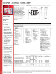
1
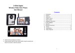
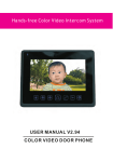
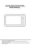
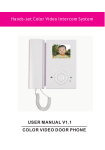
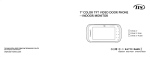
COLOR VIDEO DOOR PHONE
USER MANUAL
Thank you for purchasing our products.
The company is not responsible for any safety accidents caused by abnormal
operation of the product.
Please carefully read this User's Guide(in particular, precautions for safety) before
using this product .
Index
Warning and Caution
1
The function and name of each part
3
Features and main function
4
Package contents
4
System layout
5
Wiring diagram
6
Installation method
8
Cable specification
9
Incoming call answer
10
Monitor doorbells or CCTV cameras
10
Broadcast function
10
Internal call among monitors
11
Talking volume adjust
11
Brightness/color/contrast/display model adjust
11
Don't disturb function
11
Monitor listening
12
Connecting outdoor station with image capturing function
12
System main menu
14
Specification
15
Version1.0
Warning and caution
Make sure to follow the instructions to prevent any danger or property losses.
It indicates prohibition.
Warning
Death or serious
injury is expected.
It indicates disassembly.
It indicates prohibition of contact.
It indicates dos and don’ts.
It indicates that the plug should be pulled out from
the socket.
warning
NO
Do not put the plug in the
socket simultaneously.
It may generate abnormal
heat or cause a fire.
NO
Do not use water, thinner or
a detergent used to wash oil
products when you wash the
exterior.
Make sure to wash it by using
a dry cloth to prevent any
breakdown or electric shock.
Do not put the plug in the
socket with a wet hand.
It may cause an electric
shock.
NO
Do not connect to other
products while in use.
It may cause breakdown.
NO
Do not install the product in a
humid place.
It may cause an electric
shock or a fire.
NO
Do not forcibly bend the cord
or put a heavy object on the
product.
It may cause a fire.
NO
Do not forcibly pull out the
cord from the socket.
If the cord is damaged, it
may cause a fire or an
electric shock.
Do not disassemble, repair
Do not use AC circuit breaker.
or modify the product.
It may cause an electric shock.
It may cause a fire, an electric
shock or an injury due to
malfunction of the product.
Page1
It indicates prohibition.
Caution
A injury or property
losses are expected.
It indicates disassembly.
It indicates prohibition of contact.
It indicates dos and don’ts.
It indicates that the plug should be pulled out from
the socket.
CAUTION
The socket holes
are lager than
usual.
NO
NO
If the socket holes are larger
than normal, do not put the
plug.
It may cause an electric shock
or a fire.
Make sure that dust or
foreign substances are not
gathered on the product.
NO
Make sure to prevent foreign
substances from entering
the product.
It may cause a breakdown.
NO
Do not put a heavy object on
the product.
It may cause a breakdown.
Install the product in a flat and
stable place.
Otherwise, it may not function
properly.
Page2
Do not disassemble the
product.
Pull the plug if the product is
not used for a long time.
Avoid direct rays of the sun
or heating devices at a time
of installation.
If the product generates
strange sound, make sure to
pull the plug immediately
and contact service center.
The function and name of each part
10
2
1
11
3
3
4
5
6
7
8
9
10
No. Item
Function description
1
Speaker
2
LCD
3
Menu button
Enter system settings
4
Left button
Adjust -
5
Right button
Adjust +
6
Answer button
Answer/Call
7
Monitor button
Monitor
8
Unlock button
Unlock
9
Back button
Back/hang up
10 Indicator light
Power indicator light
11 Microphone
Page 3
Features
and main function
MODEL LIST
1.Features
7" color digital LCD, high definition
Hands free design, perfect intercom with clear voice
comfortable touch button
The optional multi-language, friendly interface
12 polyphonic ring-tones switch freely
Simple operation
2.Main function
Unlock
Broadcast function
Monitor listening
Call transfer
“Don't disturb” function
Make internal call to other monitors
Real-time monitoring to doorbell or CCTV camera
Brightness, contrast, volume, display model and color adjustable
The indoor monitor can take pictures if it works together with an
outdoor station which is with picture taking and saving funciton.
Package contents
Us er
ma un
al
Monitor
User manual
Wall bracket
2* M3.5* 30
fixing screws
5 pin connector
(red/blue/yellow/
white/brown)
2*4 pin connector
(red/blue/yellow/
white)
Page 4
2 * Expansion bolt
Desiccant
4 pin connector
(white/blue/
white/blue)
Adaptor
System layout
1.The port 2 connect doorbell panel
The system can maximum support 1 main monitor, 3 sub monitors, 2 door
panels and 8 CCTV cameras.
MAIN MONITOR
SUB MONITOR
SUB MONITOR
SUB MONITOR
DOORBELL1
CCTV1
CCTV1
CCTV1
CCTV1
CCTV2
CCTV2
CCTV2
CCTV2
DOORBELL2
2.The port 2 connect the CCTV camera
The system can maximum support 1 main monitor ,1 door panels, 9 CCTV
cameras and 3 sub monitors .
MAIN MONITOR
SUB MONITOR
SUB MONITOR
SUB MONITOR
Doorbell
CCTV1
CCTV1
CCTV1
CCTV1
CCTV2
CCTV2
CCTV2
CCTV2
CCTV3
Page 5
Wiring diagram
Solution1
P3
P6
AD-1
+15V
GND
DATA
GND
a
VD-1
electronic lock 2
P2
AD
GND
PWR
VD
COM
NO
Doorbell 2
AD2
GND
PWR2
VD2
P4
CCVT1
CCVT2
ROOM1
P1
CCTV1
AD1
GND
CCTV2
GND
GND
PWR1
VD1
AD
GND
COM
PWR
VD
NO
DATA
DoorBell 1
P3
P6
+15V
SYSTEM DIAGRAM
electronic lock 1
SYSTEM DIAGRAM
AD-1
GND
DATA
GND
VD-1
P2
AD2
GND
PWR2
VD2
P4
CCTV1
CCVT1
AD1
GND
PWR1
VD1
GND
CCTV2
GND
CCVT2
ROOM2
P1
DATA
P3
P6
AD-1
+15V
GND
DATA
GND
VD-1
P2
AD2
GND
PWR2
VD2
P4
CCVT1
AD1
GND
PWR1
VD1
GND
CCTV2
GND
CCVT2
ROOM3
P1
CCTV1
DATA
P3
P6
AD-1
+15V
GND
DATA
GND
VD-1
P2
AD: Audio
VD: Video
PWR: Power
GND: Ground
DATA: Communication
CCTV: CCTV camera
AD2
GND
PWR2
VD2
P4
CCTV1
CCVT1
CCVT2
ROOM4
P1
GND
CCTV2
GND
AD1
GND
PWR1
VD1
DATA
Note: Door panel unlock wiring: electronic lock 2 + external power supply.
Page 6
Wiring diagram
Solution2
P3
P6
AD-1
+15V
GND
DATA
GND
VD-1
P2
AD2
GND
PWR2
VD2
CCVT3
P4
CCTV1
CCVT1
AD1
GND
PWR1
VD1
GND
CCTV2
GND
CCVT2
ROOM1
P1
AD
GND
PWR
VD
COM
NO
DATA
DoorBell 1
SYSTEM DIAGRAM
electronic lock 1
P3
P6
AD-1
+15V
GND
DATA
GND
VD-1
P2
AD2
GND
PWR2
VD2
P4
P1
AD1
GND
PWR1
VD1
CCTV1
CCVT1
GND
CCTV2
GND
CCVT2
ROOM2
DATA
P3
P6
AD-1
+15V
GND
DATA
GND
VD-1
P2
AD2
GND
PWR2
VD2
P4
AD1
GND
PWR1
VD1
CCTV1
CCVT1
GND
CCTV2
GND
CCVT2
ROOM3
P1
DATA
P3
P6
AD-1
+15V
GND
DATA
GND
VD-1
P2
AD2
GND
PWR2
VD2
P4
CCVT1
CCVT2
ROOM4
P1
CCTV1
GND
CCTV2
GND
AD1
GND
PWR1
VD1
DATA
Page 7
Installation
method
SINGLE MONITOR INSTALLATION
1.Refer to relevant wiring diagram for the system you have chosen and ensure you
have the correct cable.
2.Determine the monitor installation position:
-suggest to install at 1.5~1.6Meters;
-suggest distance between indoor monitor and doorbell is at least 350 mm;
3.Ensure no power supply connection before installation finished
4.Take off the bracket from the back of the monitor.
5.Install the bracket on the wall
6.Connect cables as per the wiring diagram indicated.
7.Fix the monitor onto the bracket.
8.Connect power when doorbell is installed.
150cm
Page 8
Cable
Specification
Cable
specification
Our system has 1 solution to unlock the door: Unlock signal from doorbell.
(The cable shield wire needs to be grounded)
When signal from the doorbell,cable specification is:
2
Distance between monitor and door station is less than 30 meters, RVV 4*0.3MM
cable is available;
indoor monitor
AD1
GND
PWR1
VD1
Red
Blue
Yellow
white
1
2
3
4
1
2
Red
Blue
3
4
Yellow
White
DATA
AD
GND
PWR
VD
+
Green
12V
Orange
-
COM
NO
+
-
electronic lock
2
outdoor panel
Distance exceed 30 meters, please choose professional cable SKV-75-3+ P VV
2*0.5mm2 (recommend);
indoor monitor
AD1
GND
PWR1
VD1
DATA
Red
Blue
Yellow
White
1
1
2
2
3
3
Red
Blue
Yellow
White
AD
GND
PWR
VD
Green 12V +
Orange
-
COM
NO
+
-
electronic lock
outdoor panel
Page 9
Incoming call answer
When a visitor presses doorbell, all the indoor monitors in this house will
chime simultaneously, the LCD will show “INCOMING CALL”. Press
to
talk with the visitor. The monitor will return to standby state if no one answers
after chime time ends. At ringing and answering state, Press
button to
unlock the door for the visitor, and the LCD will show “DOOR UNLOCKED”. If
there is another incoming call when talking with Door 1 , the LCD will show
“SOMEONE IS VISITING AT DOOR 2”, then press
can switch the display
image to Door 2 and talk with another visitor.
Note: At the state of answering or intercom between monitors, long press
button, the microphone will be mute, and the LCD will show “MUTE”, long
press
button again the microphone return to normal, and the LCD will
show “PLEASE TALK”.
Monitor doorbells/CCTV camera
At standby state, press
button to monitor Doorbell 1, press
again,
change the viewing screen to another video channel. When monitoring Door
bell channel, press
can talk with people in front of the door bell, and press
can open the door.
Broadcast function
At standby state, long press
button, the screen will show BROADCAST
REQUEST, the monitor in other rooms will show BROADCASTING . Now you
can make broadcast .
Page 10
Internal call among monitors
If you make intercom request to all monitors . At standby status, press
button to call other monitor, If you have more than 2 monitors connected
together in the system, please press
or
to select target monitor, press
button to confirm calling. The user at another room can press
answer the call, or press
to
to hang up.
Talking volume adjust
At the state of monitoring, ringing, talking, making intercom, broadcasting,
press
or
to enter volume adjustment interface. press
or
again
to adjust the talking volume,
Brightness/color/contrast/display model adjust
At monitoring , ringing, making intercom state, press
volume adjustment interface. press
display model interface, press
or
or
to enter
can switch to BRIGHT/CONT/COLOR/
to adjust as the user wants.
“Don’t disturb” function
You can use SYSTEM SETTINGS menu to turn “DO NOT DISTURB” function
on or off. If enable this function, there will be no chime during ringing, intercom,
broadcast,
Monitor listening
At standby state, long press
button to start the monitor listening function.
If you have more than 2 indoor monitors ,there would be option rooms for
Page 11
choosing on screen, press
and press
or
to choose the target indoor intercom
to confirm.
Note:
a: When monitoring, the user can hear the sound from the being monitored
room,but the people at the be-monitored intercom room can not hear the voice
from monitoring intercom room.
b: Monitor listening function is only available when BE MONITORED function
in the target monitor is enabled. Please check the system setting menu to see
how to enable the BE MONITORED function.
Connecting outdoor station with image capturing
function
1. Capture the image of the visitor
Auto capturing: The model will auto take a picture when a visitor presses the
outdoor panel.
Manual capturing: At monitoring and answering state, long press
button
to capture the image on the screen, and actual capturing time will show on the
top right corner when the image saved.
2. View the images/photos
At Standby state, press
button to monitor door panel 1, press
again to enter doorbell photo checking menu. Please press
choose
, then press
or
button
to
button to view images, The first
picture is the one taken in the nearest time. If want to delete the picture,press
button to enter delete menu, select
Page 12
to confirm the deletion,
or select
to cancel the deletion. Users can press
button to exit the
doorbell photo check menu.
3. Set the system time
At Standby status, press
button to monitor Doorbell 1, press
again to Doorbell 1 photo check menu. Then press
30
, press
or
button
button to choose
button to enter the system clock setting interface, press
to adjust time, press
or
button again to exit the adjustment items.
After adjusting all the time, then select
to save the time or select
cancel and return back. At any time press
to
button can exit the operation.
4. Delete all images
At Standby status, press
button to monitor Doorbell 1, press
again to Doorbell 1 photo check menu, press
, then press
button to choose
button to enter all picture deletion interface, select
to confirm the deletion, or select
press
or
button
to cancel and return back. At any time
button to exit the operation.
Note:
a, If need to use the picture taking function after connecting with a doorbell
which with picture taking function, please go to system setting and enable
“PHOTO FOR DOOR1" or “PHOTO FOR DOOR2".
b, After set the time in the system, the clock can keep running for about two
days if the doorbell does not connect to the indoor monitor.
Page 13
System setting
In standby status ,short- press
button to enter system setting menu.
No.
Setting items
1
LANGUAGE
Default English(Russian optional)
2
CHIME TIME
Default 30seconds, (10 - 60 seconds adjustable)
3
CHIME VOLUME
Default 07, 01 - 10 adjustable.
4
RING TYPE
Options
Notes
Door1 ring type
01 by default, 00-11 optionals
Door2 ring type
02 by default , 00-11 optionals
Intercom ring type
03 by default , 00-11 optionals
Off by default, at the ringing, intercom between monitors,
5
DO NOT DISTURB
broadcast status, the LED indicator will flicker when turn
on “DO NOT DISTURB” function.
CAN BE
6
MONITORED
Off by default, it can be monitored by other indoor
intercoms in the system when turn on this function.
Master monitor must be set as ROOM
7
DEVICE ADDRESS
Room1/2/3/4
1, and the option will be yellow if two
monitors set the same address.
8
9
10
11
12
Page 14
PORT4 STATE
MONITOR
UNLOCK
PHOTO FOR
None / CCTV1 / CCTV1&2
Press
button to unlock
Off by Default, please enable this option after Port 1
DOOR1
connecting with doorbell with image capturing function.
PHOTO FOR
DOOR2
Off by Default, please enable this option after Port 2
connecting with doorbell with image capturing function.
RESTORE
DEFAULT
Restore the system to default settings.
Specification
No.
Items
Content
1
Power source
DC15V
2
Power consumption
7W(Max), 1W(In standby)
3
Operation temperature
0 C to +50 C
4
Operation humidity
0% - 95%
5
Display panel
7 inch
6
Intercom function
Hands-free
7
Connection
4 wires
8
Dimension
185mm*127.5mm*18mm
9
Weight
360g
Page 15
Page 30
The parameters of product are subject to changes without prior notice.