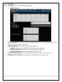
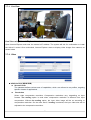
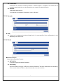
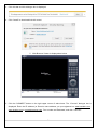
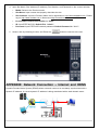
1
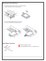
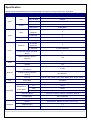
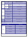
EZPZ IP Kit (Ver. 1.1) H.264 Video Compression Network Video Recorder & IP Camera User Manual About this User Manual Before installing, or operating the unit, please read this manual thoroughly and retain it for future reference. Safety Precautions Explanation of Graphical Symbols This symbol indicates the presence of important operating and maintenance (servicing) instructions in the literature accompanying the product. This symbol indicates the presence of uninsulated ”dangerous voltage” within the product’s enclosure that may be of sufficient magnitude to constitute a risk of electric shock to persons. WARNING To reduce the risk of fire or electric shock, do not expose the NVR to rain or moisture. CAUTION Changes or modifications not expressly approved by the manufacturer may void the user’s authority to operate this equipment. CAUTION There’s a danger of explosion if the battery is replaced incorrectly. Only replace with the same or equivalent type of battery; as recommended by the manufacturer. Discard used batteries environmentally and according to the manufacturer’s instructions. 2 These precautions must be followed for safety reasons Warning Do not use if the unit emits smoke, strange sounds, or odours are emitted. Make sure the power cable is not damaged. Make sure there is no dust accumulation on the power plug or the outlet. Disassembly is prohibited Do not place any foreign objects inside the devices. Do not allow the NVR unit to get wet. Do not use during thunder storms without appropriate lightning protection. Do not install the devices in unstable positions. Do not expose to shocks or vibration. Do not use this unit in areas where it is exposed to the possibility of explosion. Caution Do not pull on the power cable when removing the power plug from the outlet. Do not touch the power plug with wet hands. Make sure the cables are connected properly. Do not place heavy objects on connected units. Never move this unit while power is switched on. Remove the power plug from the outlet if the unit is to remain unused for long periods of time. Do not block the cooling fans or air ducts. Do not expose to extreme temperatures or humidity changes. Warning Installation and servicing should only be performed by qualified and experienced personnel. Turn off the power of the NVR when connecting cameras, audio or sensor cables. The manufacturer is not responsible for any damage caused by improper use of the product or failure to follow instructions for the product. The manufacturer is not responsible for any problems caused by, or resulting from, the user physically opening the NVR for examination or attempting to fix the unit. The manufacturer may not be held liable for any issues with the unit if the warranty seal is removed. For NVR PoE models with a PoE Switch, it’s strongly recommended that the 48V connector is inserted into the PoE Switch before the AC cable is attached to the adaptor. 3 Product Components The package contains the main unit and its components. When you purchase the unit, please check to ensure the components specified below are included. EZPZ NVR Unit 4x EZPZ IP Camera (PoE) Remote Control Battery1.5V (2x AAA) Quick User Guide Mouse for NVR Software & Manual CD HDD Power & SATA Cable HDD Mounting Bracket & Screws / HDD Fixing Screws Adaptor (DC12V 3A for NVR) & Power Cable (AC110-220V) Adaptor (PoE Only) (DC48V 1A for NVR) & Power Cable (AC110-220V) 4 Mounting the Hard Disk Drive 1. Remove the screws and the top cover as shown below. 2. Mount the HDD into the mounting bracket. . 3. Insert the HDD bracket and mounting screws. 4. Connect the HDD SATA and power cable. Basic Mouse Functions ① Left Button: SELECT function ② Wheel: MOVEMENT function on a drop-down menu 5 Specification Please note that specifications and unit exterior design are subject to change without prior notification MODEL EZPZ NVR Input IP Camera 4 Max. Bit Rate 20Mbps Resolution Maximum 1920 x 1080 Main Monitor VGA and HDMI Sub Monitor CVBS (BNC) Video Output IP Camera 4 (Network) Input Local Input 4 Local Output 1 Audio Output Audio Codec G.711 IP Camera 4 (Network) Sensor In Local Input Event 4 (Terminal Block) Local Alarm Output (Terminal 1 Block) Motion Detection (from IP Yes Camera) Serial RS-232C Yes (Engineering Use Only) RS-485 Yes Private (IP Camera, Auto 4x PoE Connection) Network LAN (IP Camera, Remote 10/100 Base-T Access) Live Protocols TCP/IP, UDP, DHCP, HTTP, NTP, SMTP, RTP, RTSP, ONVIF Frame Rate 120/100fps Compression H.264 (Baseline, Main, High Profile) Resolution & Recording Playback Frame Rate D1 120fps 720p 120fps 1080p 120fps Recording Mode Continuous / Motion / Sensor / Schedule / Manual Pre Recording Max. 20 Minutes Post Recording Max. 60 Seconds Search Quick Search, Date/Time, Event, Archive, Log Multi-Decoding 1, 4 Playback Speed x0.25, x0.5, x2, x4, x8, x16, x32, x64 6 Backup Media USB Drive, External HDD, Network File Format BMP, AVI, Proprietary Format Backup Max. 24 hours Max. Capacity Storage Internal HDD’s 1 Front 1 (For Archiving Footage) Rear 1 USB User I/F 3TB of HDD HDD Input Method IR, Mouse, Keyboard Controller Dynamic DNS Yes (Free DDNS) Digital Zoom Yes DLS (Day Light Saving) Yes NTP (Network Time Protocol) Yes S.M.A.R.T Yes Internal Beep Yes Multi-Language Yes e-mail Notification Yes Mobile iPad / iPhone / Android Network Web Viewer Windows (IE10, Chrome, Firefox, Safari), MAC (Single Site Client) Access PC Client Single / Multi Client and CMS (64 Channels) Remote Setup and Upgrade Yes Power Power Supply Voltage DC12V 3A + DC48V 1A (POE) Temperature Operating Temperature 41°F ~ 104°F (5°C ~ 40°C) Weight Unit Weight (Gross Weight) Approximately 6Kg Dimension Unit Dimension (W x H x D) 340mm x 262mm x 63mm Features MODEL EZPZ IP Camera Feature 2.1MegaPixel, IR Vandal Dome Sensor 1/2.8" 2MP Progressive Sensor Shutter Speed 1/8 ~ 1/30,000 sec Minimum Illumination Camera 1 Lux @ F1.2 Without DSS SNR 0.00001Lux @ F1.2 (LED’s ON) Lens Mount Type Fixed (3.7,6.0) Lens Type Manual IR LED 12x IR LED’s Auto Exposure Fixed White Balance Auto Gain Control Auto 7 Network Video Security Mechanical Spec. Image Adjustment Fixed Motion Detection Yes Sharpness Fixed D Noise Reduction Fixed Flip/Mirror Fixed Day & Night Auto Interface 10/100 Base-T Maximum Simultaneous Users 4x Users Web Browser Internet Explorer 10 Web Language English Compression Dual Streaming (H.264/H.264) Maximum Video Resolution 1920 x 1080 Maximum Frame Rate 30fps Bitrate 32~10, 2400 Kbps Bitrate Control Method CBR HTTPS Encryption Yes User Management Yes Voltage DC12V, PoE (DC48V) Power Consumption Maximum 2.5W Operating Temperature -4° F ‒ 122° F Weight 1300g Dimensions 80(Ø) x 80 (H) mm Please note that specifications and unit exterior design are subject to change without notification 8 Table of Contents 1. Main Features................................................................................................................................. 11 2. Initial Boot-Up Process ................................................................................................................... 11 2-1. Initial Boot Up and Basic Time Setup ........................................................................................ 11 2-2. Setting Daylight Savings Time ................................................................................................... 11 2-3. Setting NTP (Network Time Protocol) ........................................................................................ 12 2-4 QUICK INSTALLATION .............................................................................................................. 13 2-5 PoE Port Setup ........................................................................................................................... 15 2-6 IP Camera Setup (Through Web Viewer Page) .......................................................................... 17 2-7 Dual Streaming............................................................................................................................ 17 3. Front and Rear Panels ................................................................................................................... 18 3-1. Front Panel ................................................................................................................................ 18 3-2. Rear Panel ................................................................................................................................. 18 3-3. Remote Control .......................................................................................................................... 19 4. Setting up the NVR ......................................................................................................................... 21 4-1. Setup – Main Live Screen .......................................................................................................... 21 4-1-1. Setup – MENU TREE ............................................................................................................. 22 4-2. Setup – EZPZ IP Camera .......................................................................................................... 24 4-2-1. SCAN Menu ............................................................................................................................ 26 4-3. Setup – DISPLAY ...................................................................................................................... 26 4-4. Setup – RECORD Mode ............................................................................................................ 28 4-4-1. Recording Schedules .............................................................................................................. 29 4-5. Setup – DEVICE Mode .............................................................................................................. 30 4-6. Setup – STORAGE Mode .......................................................................................................... 31 4-7. Setup – SYSTEM Mode ............................................................................................................. 32 4-8. Setup – SECURITY Mode ......................................................................................................... 36 4-9. Setup – NETWORK Mode ......................................................................................................... 38 4-9-1. Network Port and Web Port .................................................................................................... 39 4-9-2. Network Types ........................................................................................................................ 39 4-9-3. DDNS ...................................................................................................................................... 40 4-10. Setup - CONFIG Mode ............................................................................................................ 41 4-10-1. Firmware Upgrade ................................................................................................................ 42 6. Live, Search and Playback ............................................................................................................. 44 5-1. Live View .................................................................................................................................... 44 5-1-1. PTZ Control ............................................................................................................................ 48 5-2. Digital Zoom in Live and Playback Screen ................................................................................ 48 5-3. SEARCH Screen ........................................................................................................................ 49 5-3-1. QUICK Search ........................................................................................................................ 49 5-3-2. Time Line Search .................................................................................................................... 50 5-3-3. Event Search .......................................................................................................................... 51 9 5-3-4. Go To First Time ..................................................................................................................... 52 5-3-5. Go To Last Time ..................................................................................................................... 52 5-3-6. Go To Specific Time ............................................................................................................... 52 5-3-7. Archive List ............................................................................................................................. 53 5-3-8. Log List ................................................................................................................................... 53 5-4. Play Mode .................................................................................................................................. 54 6. Back-Up ............................................................................................................................................. 55 6-1. Still Image Back-Up onto USB Flash Drive ................................................................................ 55 6-2. Video Backup onto an USB Flash Drive .................................................................................... 55 6-3. Transferring Still Images or Video from the ARCHIVE List ........................................................ 56 6-4. Playback of Backup Video ......................................................................................................... 57 7. Network Access Using the EZPZ Viewer........................................................................................... 58 7-1. Overview .................................................................................................................................... 58 7-2. PC Requirements ....................................................................................................................... 58 7-3. Installation of the Program ................................................................................................. 59 7-4. Live Window ........................................................................................................................... 60 7-4-1. Main User Interface .......................................................................................................... 60 7-5-1 IP Camera ................................................................................................................................ 61 7-5-2 Display ..................................................................................................................................... 61 7-5-3. Record .................................................................................................................................... 62 7-5-4. Device ..................................................................................................................................... 63 7-5-5. STORAGE .............................................................................................................................. 64 7-5-6. SYSTEM ................................................................................................................................. 65 7-5-7. SECURITY .............................................................................................................................. 67 7-5-8. NETWORK ............................................................................................................................. 68 7-5-9. UPGRADE .............................................................................................................................. 68 7-6-1 Information ............................................................................................................................... 69 7-6-2 IP Camera Setup ..................................................................................................................... 69 7-7-1. Live View ................................................................................................................................ 70 7-7-2. Video ....................................................................................................................................... 70 7-7-3. Security ................................................................................................................................... 71 7-7-4. Event ....................................................................................................................................... 71 7-7-5. Network ................................................................................................................................... 72 7-7-6. System .................................................................................................................................... 72 8. Network Access Using the Web-Browser Viewer .............................................................................. 73 9. Network Access Using the Smart Phone Viewer ............................................................................... 76 9-1. App Viewer for iPhone ............................................................................................................... 76 9-2. App Viewer for Android Phone ................................................................................................... 79 APPENDIX: Network Connection – LAN ............................................................................................... 82 APPENDIX: Network Connection – Internet and DDNS ........................................................................ 83 10 1. Main Features Automatic IP Camera Detection and Connection (Plug & Play) Easy Record, Setup and Backup Easy Search by Thumbnail Preview Easy IP Camera Setup Covert Camera Operation Provides Enhanced Security and Administrator Control Dynamic Programmable Recording Priority, Motion Detection, Alarms and Scheduling Simple and Easy to use Graphical User Interface HDMI Output VGA Output Password Protection USB 2.0 Port for Video Clip Export Still Image, Proprietary Format, AVI and MAC AVI Compatible Format Options Variety of Ways Network Access via CMS Network Client Software, Web-Viewer, and Mobile Viewer (Configuration Required) 2. Initial Boot-Up Process 2-1. Initial Boot Up and Basic Time Setup 1. During the first boot up, the following logo is displayed. 2. Following the logo, select the language and set the date and time; as indicated below: 2-2. Setting Daylight Savings Time To enable the Daylight Savings feature/NTP synchronisation, take the following steps: 1. Enter SETUP mode. The default User Name is “ADMIN” and the Password is “1111”. 11 2. Go to SETUP > SYSTEM > DATE & TIME SETUP 3. Select ON from the DAYLIGHT SAVINGS dropdown menu. 2-3. Setting NTP (Network Time Protocol) 1. SETUP > SYSTEM > NTP SETUP > ON 12 2. Select the correct TIME ZONE time. NOTE: If you want the unit to automatically synchronise to the local time, the Time Zone must be set to your local time zone. 2-4 QUICK INSTALLATION Quick installation Menu for EZPZ NVR and EZPZ IP Camera (Right-Click on the Main Screen) 2.4.1 Helps Users to Setup the NETWORK Settings (Using an Internet Connection) 13 1 2 3 4 5 6 ① Select YES when setting the network using an internet connection. ② Select Auto Configuration (DHCP) or Manual Configuration (STATIC), and then click the TEST Button. This automatically sets up the network for the system (NVR). ③ Setup DDNS setting. DDNS (Dynamic Domain Name System) allows a DNS name to be constantly synchronised with a dynamic IP address. It allows using a dynamic IP address to be associated with a static domain name and associates a dynamic IP address with a static domain name. ④ Click Finish to save the setup. 2.4.2 Helps Users to Setup the EZPZ IP Camera Settings 14 ① Select the Channel to configure. ② Select the Camera Manufacturer and then click on the scan button; this scans the network for any cameras from that particular manufacturer. ③ Select the desired Camera from the list, and then click on Register. ④ If necessary, click on Preview to preview the camera, or Setup to change the camera settings. 2-5 PoE Port Setup Figure 2.5.1. PoE Port 2.5.1 Connecting the Cameras (PoE Model) 15 The following IP Camera settings are recommended for optimum connection to the EZPZ NVR Setup Items Default Description Network Type DHCP The IP Camera must act as a DHCP client for the “Plug and Play”. Encoding Type CBR CBR is recommended - because of the internal buffer strategy of the EZPZ NVR. Dual Streaming General Sub Stream must be turned ON. The compression, for both the Main and Sub Stream, must be H.264. Main 1920 x1080@30fps, 5Mbps (Max. throughput of the NVR is 20Mbps) Audio Sub D1@30fps, 1Mbps G.711 Only the G.711 Codec is supported • The EZPZ Series features a "Plug and Play" function with a PoE Switch. • The “Plug and Play” functionality requires the IP Camera to be in DHCP mode. • The NVR automatically assigns an IP Address to the IP Camera (192.168.78.11 ~ 254). • The EZPZ NVR automatically maps a camera on the PoE Port to the corresponding NVR channel number. Clients NOTE: With the EZPZ IP Kit, DO NOT USE a router connection to connect an IP Camera. The NVR will not be able to find the camera, or connect to it. The LAN Port can be connected to a router, but not the PoE Ports. 16 2-6 IP Camera Setup (Through Web Viewer Page) EZPZ IP allows remote access to the IP Cameras through the "IP Camera Setup" menu in the Web Client Viewer. ① Click the right mouse button ② Select “IP Camera Setup”. ③ Select Channel Number. ④ This lanuches the camera’s own setup page. In order for the web pages to launch the “IP Camera Setup” menu (when accessed from the WAN), Ports 59011 to 59254 on the router must be port forwarded to the NVR. The local address of the NVR can be found in System Information. 2-7 Dual Streaming High Quality (Main Profile) Video Stream is used for both Recording and Live Display. High Quality (Main Profile) Video Stream can be viewed through the Network, when selected. Normal (Secondary) Quality Video Stream is used by default when viewing through the Network. Monitoring 17 3. Front and Rear Panels 3-1. Front Panel The following information describes the front panel controls. ① POWER: LED light is ON when power is applied to the system. ② HDD: LED light is ON when the system is recording video data. ③ LAN: LED light is ON when connected to the network. ④ ALARM: LED light is ON when the alarm output is turned on. ⑤ USB PORT: This USB port is for archiving footage onto a USB device (USB 2.0). 3-2. Rear Panel Do not power the system ON before all the connections are complete. Make sure all connections are properly secured. Faulty connection may result in the system being damaged. 1 4 3 10 5 11 8 6 2 7 9 No. Connection Purpose 1 GROUND Use for Ground Port 2 POE POWER Connect DC48V 1A PoE Adapter 3 POE PORT 4x PoE Port 4 AUDIO IN/OUT 4x Connectors for Audio Input/1x Connector for Audio Output 5 CVBS OUT Main – Composite Video Output 6 HD VIDEO HDMI Connector for Main Video Output. 7 VGA OUT Connector for VGA Monitor. 8 RS-232C For Engineering Use Only. 18 12 9 USB Port USB Terminal for Video Export or Firmware Upgrade 10 ETHERNET RJ-45 Connector for LAN Connection, used for Internet Connection. 11 SENSOR IN 4x Connectors for Sensor Device Connection. ALARM OUT 1x Connector for Alarm Device Connection. Provides Simple ON/OFF Switching Using Relay. 0.5A/125V, 1A/30V 12 RS-485 RS-485 Control Terminal (D+, D-) POWER Connect DC12V 3A Power Adapter 3-3. Remote Control ① ID: To set the remote control ID. ② REC: To start and stop manual recording. ③ SEARCH: To go to the SEARCH menu. ④ F/ADV: During PLAYBACK – To move the Playback position 60 seconds forward. During PAUSE – To move the Playback position moves 1 frame forward. ⑤ F/REW: During PLAYBACK – To move the Playback position 60 seconds backwards. During PAUSE – To move the Playback postion 1 frame backwards. ⑥ FF: To Fast Forward the recording. ⑦ PLAY/PAUSE: To Play or to Pause the recording in Playback mode ⑧ REW: To rewind the recording. ⑨ ESC: During Setup – To retun to the preivous menu screen. During Playback – To exit Playback mode System Lock – Locks a system by pressing the ESC button for 5 seconds. System Unlock – Unlocks a system by pressing the ESC button for 5 seconds. 19 ⑩ SETUP: To open the SETUP menu. ⑪ Direction Buttons: To move between menu items or to select a channel. ⑫ SEQ: To start auto sequencing the screen in full screen mode (Toggle). ⑬ BACKUP: To start a Backup operation in Live or playback mode ⑭ 0~9: To select a Channel (1,2,3,..), or to enter a NVR ID number, or use as number key. 20 4. Setting up the NVR The following sections detail the initial setup of the NVR. Menu screen closes if no user input is received after a period of 5 minutes elapses. 4-1. Setup – Main Live Screen To enter the Setup Menu, click the right mouse button and select SETUP from the submenu, or press the Setup button on the remote control. When the EZPZ NVR prompts you with the LOG-IN window, enter the PASSWORD using the virtual keyboard or the remote control. The factory default password is 1111. It’s highly recommended you assign a new password to protect the system. Users can assign a new password in the SECURITY setup menu. 21 4-1-1. Setup – MENU TREE IP CAMERA – VENDOR - SCAN - IP - PORT - WEB PORT - PROTOCOL – OSD – OSD CONTRAST – SEQUENCE – SEQUENCE DWELL TIME – CHANNEL - NAME - COVERT VIDEO OUTPUT RECORD – - DISPLAY – CHANNEL CHANNEL - RECORDING - SENSOR RECORDING - PRE RECORD - POST EVENT RECORD - AUDIO - SCHEDULE DEVICE – ALARM OUT - – CONTROLLER & PTZ - – ALARM DURATION CONTROLLER - SPEED - ID CHANNEL - AUDIO SOURCE – KEY TONE – REMOTE CONTROLLER ID – SENSOR - – TYPE IEE 802.3af POE STATUS 22 STORAGE – OVERWRITE – DISK FORMAT – DISK INFO – RECORDING LIMIT - RECORDING LIMIT DAYS SYSTEM – NVR-ID – DESCRIPTION – LANGUAGE – DATE FORMAT – SET DATE & TIME - TIME DISPLAY FORMAT - TIME ZONE - DAYLIGHT SAVING - SET DATE & TIME – CLIENT ACCESS – NTP – SEND EMAIL – SYSTEM EVENT NOTIFICATION SECURITY – USER AUTHENTICATION – USER NAME – USER PASSOWRD – PLAYBACK AUTHORITY – NETWORK LIVE AUTHORITY NETWORK – PORT – NETWORK AUDIO PORT – WEB PORT – NETWORK TYPE (DHCP, STATIC) – - IP - SUBNET MASK - GATEWAY - DNS (PRIMARY) - DNS (SECONDARY) DDNS - OFF - DDNS SERVER 1 - DDNS SERVER 2 - DDNS SERVER 3 23 CONFIG – SAVE SETUP TO A USB – LOAD SETUP FROM A USB – LOAD DEFAULT – LOAD FACTORY DEFAULT – SOFTWARE UPGRADE 4-2. Setup – EZPZ IP Camera Press the SETUP button and enter the password. The setup menu is displayed as picture below. Item CHANNEL Description To manually connect each camera, click on the to get to this window: TYPE: Under the column labelled Type, Select the IP Camera Manufacturer. 24 SCAN: Double click the empty box to search for IP cameras on the local network. IP: Enter the address of IP camera to connect, or select from the scanned list. PORT: Enter the port number of IP camera to connect. WEB PORT: Enter the web port number of the IP camera to connect. OTHERS: Change the IP camera setting. Double click the empty box and the Login box pops up (Enter the ID and Password of IP Camera). VENDOR SCAN IP PORT Select the Brand of Camera. Automatically search the network for EZPZ IP Cameras. Enter the IP Address of the Camera. Enter the camera stream Port Number (the default is 554) WEB PORT Enter the camera Web Port Number (the default is 80) PROTOCOL Select a protocol (TCP only). NVR CH ID PASSWORD Select an EZPZ NVR Display channel. Enter the User ID for access to the IP Camera. Enter the PASSWORD for the associated User ID. 25 4-2-1. SCAN Menu NVR and IP Cameras connected to the same Network are discovered by Search (VENDOR Only) Figure 4.2.1.1 IP CAMERA Setup Screen (Vendor Only) ① Select the specific manufacturer of the IP Camera and then click on the Scan button ② Select the camera from the list and then click the Register button. ③ After registration is completed, the basic information is displayed. 4-3. Setup – DISPLAY In the SETUP menu, select the DISPLAY tab and the DISPLAY menu appears, as pictured below. Navigate through the menu items using the mouse, or the buttons on the remote control, and change the values of the menu items. To return to the previous setup menu screen, press the ESC button. Figure 4.3.1. DISPLAY Setup Screen 26 Table 4.3.1. Menu Items in DISPLAY Setup Screen Item Description OSD Enable/disable On-Screen Display. OSD CONTRAST Set the visibility level of the On-Screen Display (OSD 50~100) SEQUENCE Enable/disable sequential display of video in full screen mode. SEQUENCE Set the dwell time of each, single channel display in sequential display DWELL TIME mode (3~60 seconds) CHANNEL Select a channel to apply the name and covert settings changes using the mouse or the control button on the remote control. Select a channel to apply the following settings using the mouse. NAME Set the channel name. Press the right square button and set the channel name and select OK using the mouse. The name can contain up to 10 characters. COVERT Enable/disable display of the specified video channel in live display. VIDEO OUTPUT Select 1280 x 720 or 1920 x 1080. 27 4-4. Setup – RECORD Mode In the SETUP menu, select the RECORD tab and the RECORD menu appears, as pictured below. Navigate through the menu items using the mouse, or the buttons on the remote control, and change the value of the menu items. Figure 4.4.1. RECORD Setup Screen Table 4.4.1. Menu Items in RECORD Setup Screen Menu Item CHANNEL Description Select a channel for applying the following settings using the mouse or the control button on the remote control. To change the values of all channels, take the following steps. Select the following RECORDING to change the values of all channels. Assign the recording mode for the selected channel. Options are: Continuous, Motion, Schedule or Disable. SENSOR Select the sensor setting for the selected channel. RECORDING PRE RECORD Enable/disable pre-event recording. Pre-event recording time is up to 20 minutes. POST EVENT Set the post event recording time duration for the specified channel. RECORD (10~30 seconds) AUDIO Enable/disable audio recording for the specified channel. SCHEDULE Set the recording schedule. 28 4-4-1. Recording Schedules To setup a recording schedule, select SCHEDULE in the RECORD menu. Navigate through the items using the mouse or the remote control buttons. Select CHANNEL > select NONE, CONTINUOUS, MOTION or SENSOR > HIGHLIGHT AREA To copy a schedule to a different channel, select the channel from the COPY SCHEDULE menu. . Figure 4.4.1.1. Schedule Recording Setup Screen • NONE: Disable recording during the selected timeframe (highlighted in White) • CONTINUE: CONTINUOUS recording (highlighted in Green) • MOTION: MOTION recording (highlighted in Yellow) • SENSOR: SENSOR recording (highlighted in Red) • CLEAR: All of the selected channel recording settings are initialised. • COPY: Schedule of the selected channel can be copied to other channels 29 4-5. Setup – DEVICE Mode In the SETUP menu, select the DEVICE tab and the device menu appears, as pictured below. Navigate through the menu items using the mouse, or the buttons on the remote control, and change the value of the menu items. Figure 4.5.1. DEVICE Setup Screen Table 4.5.1. Menu Items in DEVICE Setup Screen Item ALARM OUT Description Only one Alarm Output is available. Set the alarm dwell time from between 5 to 60 seconds, or infinite. CONTROLLER Set the controller type, speed (baudrate) and ID. CHANNEL Select specified channel audio source setup. AUDIO SOURCE Select IP CAM Audio or Local Audio. KEY TONE Enable/disable key tone for front panel usage. REMOTE CONTROL ID Set the remote control ID. 1. Select ID. 2. Input the remote control ID number. 3. An icon on the Live Screen indicates if the remote control ID is synchronised. The options are from 0 to 99 30 SENSOR Select sensor number from 1 to 4 TYPE Set the type of sensor for the specified channel. Options are: OFF, N/O (normally open) and N/C (normally closed). IEE 802.3af POE PSE (Power Sourcing Equipment) Status Monitoring Menu STATUS 4-6. Setup – STORAGE Mode In the SETUP menu, select the STORAGE tab and the STORAGE menu appears, as pictured below. Navigate through the menu items using the mouse or the buttons on the remote control and change the value of the menu items. Figure 4.6.1. STORAGE Setup Screen Table 4.6.1. Menu Items in STORAGE Setup Screen Item OVERWRITE Description When enabled, the NVR continues recording and overwrites the oldest existing recorded data once the hard drive is full. When disabled, recording stops when the hard drive is full. 31 DISK FORMAT Once clicked, the user is asked to confirm the formatting of the Hard Drive. After confirming, the EZPZ NVR reboots, and the format sequence loads. Caution: It’s recommended you archive any data you may need in the future before formatting the hard drive. DISK INFO Hard drive information. Displays the following information: RECORDING Enable/disable recording limit. LIMIT RECORDING Set the recording limit days (1- 90 days). LIMIT DAYS If the RECORDING LIMIT DAYS is set to 1, the data is overwritten after 24 hours. 4-7. Setup – SYSTEM Mode In the SETUP menu, select the SYSTEM tab and the SYSTEM menu appears, as pictured below. Navigate through the menu items using the mouse or the remote control and change the value of the menu items. Figure 4.7.1. SYSTEM Setup Screen 32 Table 4.7.1. Menu Items in SYSTEM Setup Screen Item Description NVR ID NVR System ID Setup (Letters and Numbers Only) DESCRIPTION Press the button to view the system information. (Software Version, Storage Size, IP Address, MAC Address and DDNS Status) LANGUAGE Select the display language using the mouse or the remote control. Once a language is selected, the display language changes (English, Korean, SP Chinese, Japanese, Polish, Portuguese, Turkish, Russian, Croatian, Greek, German, Italian, Spanish, French, Thai, Farsi, Danish, TR Chinese, Finnish, Czech, Dutch). DATE FORMAT Select the date display format using the mouse or the buttons on the remote control. Options are: MM/DD/YYYY, YYYY/MM/DD, DD/MM/YYYY, YYYY-MM-DD, MM-DDYYYY, DD-MM-YYYY SET Select the display date and time using the mouse or the buttons on the remote control DATE & TIME and press the OK button. Select DAYLIGHT SAVING using the mouse or the buttons on the remote control and select the appropriate daylight saving time zone. The options are: If choosing EU or OTHERS, set the applicable conditions. The options are: OFF / USA / EU / OTHERS OFF: Daylight saving is turned off. USA: Applies the USA daylight saving time. EU: Applies the EU daylight saving time. - Select the GMT AREA using the mouse or the remote control buttons. - Set the time difference with the standard time using the mouse or the remote. OTHERS: If the time zone is neither USA nor EU, set the date and time of the daylight saving period. - Select BEGIN or END using the control button and press the SEL button. Caution - Do not set the start time to 23:00 for DLS. - DLS cannot be applied if the BEGIN and END date are the same. 33 CLIENT Enable/Disable remote access through the network. ACCESS NTP NTP (Network Time Protocol) which synchronises the time of the computer system over variable-latency data networks. PRIMARY SNTP SERVER: Input the address of the primary NTP time-server. SECONDARY SNTP SERVER: Input the address of the secondary NTP time-server. TIME ZONE: NTP synchronises with GMT (Greenwich Mean Time) regardless of geography; user must select time difference from GMT. CONNECTON MODE: Select the NTP time-server connection mode from TIME, INTERVAL, and ONCE. CONNECTION PERIOD - TIME – Refresh the time at the designated time (e.g. 1am) - INTERVAL – Every 1 ~ 24 hours - ONCE – Synchronises time only once. NTP will not synchronise unless the Connection Mode is changed. EZPZ NVR sends an E-MAIL Notification when the NTP server time is faster than the system time; with the message shown below. “NTP server time is faster than the system time. In this case, NTP server time is ignored to protect the user data. User must set the time manually. SYSTEM TIME: Mon Oct 10 13:46:49 2011 SERVER TIME: Mon Oct 10 13:33:12 2011 NVR ID: NVR IP ADDRESS: 172.16.2.77” SEND EMAIL Enable/disable the send e-mail function (ON/OFF). 34 SERVER TYPE: Select GMAIL, HOTMAIL, AOL, YAHOO or MANUAL MAIL SERVER: Enter the appropriate mail server information. MAIL PORT: Assign Mail Port number. SECURE OPTION: Select the secure mail server connection method (SSL or TLS). ID: Enter the appropriate mail server ID. PASSWORD: Enter the appropriate mail server PASSWORD MAIL TO: Enter the appropriate e-mail address to enable sending e-mail reports using the virtual keyboard. MAIL FROM: To set the e-mail address sent to the destination host. TEST : E-mail settings sends a test mail to the registered account SYSTEM EVENT NOTIFICATION HEALTH CHECK – OFF, ON (Allows the user to set MAIL STATUS period): DAILY or WEEKLY or MONTHLY EVENT AND NOTIFICATION – OFF, ON (Allows the user to set EVENT NOTIFICATION ON or OFF) HEALTH CHECK / RESTART / SHUTDOWN / PANIC RECORD - Enable Email notification in the event a problem occurs with the EZPZ NVR. ALARM-IN – Enable Email notification when the camera detects sensor input. MOTION DETECTION – Enable Email notification when the camera detects motion. NO CONNECTION – Enable Email, Beep and Alarm output notification when the camera signal is lost. HDD TEMPERATURE – Enable Email, Beep and Alarm output notification when the HDD temperature is too high. 35 HDD BAD SECTORS – Enable Email notification if the HDD has bad Sectors. HDD ALMOST FULL – Enable Email notification if the HDD is almost full. HDD FULL – Enable Email notification when the HDD is full. HDD FAILURE – Enable Email, Beep and Alarm Output notification when the HDD fails. 4-8. Setup – SECURITY Mode In the SETUP menu, select the SECURITY tab and the SECURITY menu appears, as pictured below. Navigate through the menu items using the mouse or the buttons on the remote control and change the value of the menu items. Figure 4.8.1. SECURITY Setup Screen Table 4.8.1. Menu Items in SECURITY Setup Screen Item Description USER Only the Admin User has access to the menu. AUTHENTICATION PASSWORD CHECK: Select the Checkbox to enable the functions or leave the Checkbox blank to disable the functions. • SETUP: Enable/Disable access to the Setup menu. • PB: Enable/Disable access to Playback. • PTZ: Enable/Disable access to PTZ Control. • REC OFF: Enable/Disable manual Record. • NETWORK: Enable/Disable access to Network. Selected Checkbox: The EZPZ NVR asks for a password when the chosen function is selected for all users. Blank Checkbox: The NVR will not ask for a password when the chosen function is selected for all users. 36 ADMIN, USER1, USER2, USER3: Selected Checkbox: The user can access the function. Blank: Means the user cannot access the function. USER NAME Change the name of USER1, USER2 and USER3. Click “ENTER” after re-naming. USER Options are ADMIN, USER1, USER2 and USER3. PASSWORD Select USER PASSWORD using the mouse or the buttons on the remote control and press the SEL button. Select user type and enter the current password. Then, enter a new password, enter the same password again to confirm and select OK. The message “PASSWORD CHANGED” is displayed. The factory default password is 1111. It’s highly recommended assigning new passwords to protect the system. PLAYBACK Set the Playback authority level for each user. AUTHORITY Checked box: Authorised to playback. Blank check box: No authority. 37 NETWORK LIVE Live through Network access rights settings. AUTHORITY When Users set this function, they see a user Login window. The User can select one of the user types (ADMIN, USER1, USER2, USER3) using the mouse or the buttons (◀ ▲ ▶ ▼) on the remote control. The password input screen is displayed. Users can select a password using the mouse or the buttons (◀ ▲ ▶ ▼) on the remote control. The factory default password is 1111. It’s highly recommended you assign a new password to protect the system. Users can assign a new password in the SECURITY setup menu. 4-9. Setup – NETWORK Mode Select the NETWORK tab and the network menu appears, as pictured below. Navigate through the menu items using the mouse or the buttons on the remote control and change the value of the menu items. Figure 4.9.1. NETWORK Setup Screen Table 4.9.1. Menu Items in NETWORK Setup Screen Item Description PORT EZPZ NVR Port. Default is 5445. NETWORK Set the Port for sending audio data via the network. Default is 5446 and AUDIO PORT must be the next number to the NVR Port (i.e. EZPZ NVR PORT + 1). WEB PORT Enter the port number for connection using web. Default is 80. 38 NETWORK TYPE DHCP: EZPZ NVR automatically retrieves an IP address. STATIC: Network information must be manually configured. IP Enter the IP address assigned for the EZPZ NVR SUBNET MASK Enter the Subnet Mask assigned for the EZPZ NVR GATEWAY Enter the Gateway assigned for the EZPZ NVR. DNS (PRIMARY) Enter the Primary DNS address assigned for the EZPZ NVR DNS (SECONDARY) Enter the Secondary DNS address assigned for the EZPZ NVR DDNS Dynamic Domain Name System (DDNS) allows a DNS name to be constantly synchronised with a dynamic IP address. In other words, it allows a dynamic IP address to be associated with a static domain name so others can connect to it by the static name. Enable/disable using domain name address through DDNS server. DDNS 1: Select one type from among the following three DDNS servers. DDNS 2: Select this type when you want to use another general-purpose DDNS Server. DDNS INTERVAL: Set the connection interval (5-60minutes). 4-9-1. Network Port and Web Port Connecting the EZPZ NVR through a common IP sharing device, each NVR must be assigned a unique TCP port number for access from outside the LAN. This port number is displayed on NETWORK>NETWORK PORT Setup MENU. NOTE: If you access the NVR from only within the same LAN, the TCP port number doesn’t need to be changed. To access the EZPZ NVR beyond a router (firewall), you must open the correct TCP ports for live/playback streaming, commands, remote backup and audio streaming. If these ports are not opened properly, you can’t access the NVR beyond a router. o For live/playback streaming, commands and for remote backup: Open the port number on NETWORK>NETWORK PORT menu. The default port number is 5445. o For bi-directional audio: Open the port number on NETWORK AUDIO PORT. The default port number is [NETWORK PORT number + 1]. o For web-viewer downloading and remote firmware upgrading: Open the port number on NETWORK>WEB PORT menu. The default port number is 80. 4-9-2. Network Types 4-9-2-1. DHCP An IP address is assigned by the DHCP server, which automatically assigns the IP address and other parameters to new devices. 4-9-2-2. STATIC IP address, Subnet Mask, Gateway, and DNS are manually assigned by the user. 39 • IP ADDRESS: The fixed IP address of the EZPZ NVR. • SUBNET MASK: The subnet mask. • GATEWAY: The IP address of the Gateway. • DNS (PRIMARY) The primary address of Domain Name Server • DNS (SECONDARY): The secondary address of Domain Name Server NOTE Unless DNS is properly set, the DDNS and the e-mail features will not work. 4-9-3. DDNS Users can use this function to connect to a network with a domain name. When selecting Server 1, you can select one from five DDNS Servers which are supported for free (okddns.com for Korea, ddnscenter.com for USA and bestddns.com for other areas; including the EU etc.). The DDNS interval can be set from 5 to 60 minutes. To connect to a network with a domain name, Users must also register a MAC address and create a unique domain name to use http://www.bestddns.com, http://www.okddns.com or http://www.ddnscenter.com. Please refer to Appendix: The “How to connect” network section for registration details. Figure 4.9.3.1. NETWORK Setup Screen – DDNS If you want to use another general-purpose DDNS Server, select Server 2. Then, you have to input the server name, ID and password using the virtual keyboard. Figure 4.9.3.2. Network Setup Screen – DDNS Server 2 Figure 4.9.3.3. Network Setup Screen – DDNS Server 3 DDNS HOST NAME: Set the hostname to use. HOST DOMAIN NAME: Displays the host name set. 40 4-10. Setup - CONFIG Mode In the SETUP menu, select the CONFIG tab and the configuration menu appears, as pictured below. Navigate through the menu items using the mouse or the buttons on the remote control and change the value of the menu items. Figure 4.10.1. CONFIG Setup Screen Table 4.10.1. CONFIG Setup Item Description SAVE SETUP User can save the current configuration (Setting Values) of the EZPZ NVR to TO A USB a USB flash drive. Plug in the USB flash on the front panel and press the button to start the saving process. LOAD SETUP User can upload the configuration of the EZPZ NVR to another EZPZ NVR FROM A USB using a USB Flash drive. Plug in the USB flash drive on the front panel and press the button to start the loading process. LOAD Press the button to reset the system to the default settings. DEFAULT The following settings - Language, NVR ID, Security User Authentication, Security User P/W, Date format, DLS settings, Network settings, HDD overwrite, Limit recording, HDD serial number, and HDD ERROR time will not be included. LOAD Press the button to reset the system to the factory default settings. FACTORY DEFAULT SOFTWARE Upgrade software to the latest version. UPGRADE After connecting USB flash drive to USB port on the EZPZ NVR, click SEARCH. It finds the upgrade file automatically. 41 4-10-1. Firmware Upgrade In order to upgrade, the firmware upgrade file must first be downloaded and copied into the USB memory drive. Create a new folder in the USB memory drive and name it “upgrade”. Copy the firmware upgrade file “xxxxxx.bin” into the “upgrade” folder. NOTICE The format of the USB Drive must be set to FAT32. The folder on the USB memory drive must be named “upgrade”. After the firmware upgrade file is copied into the USB memory drive, connect the USB memory drive to the USB port on the front or rear panel and do the following: 1. Go to the CONFIG menu in Setup. 2. You will see the following message displayed when pressing the software upgrade menu (after first putting the USB memory drive in the system). Figure 4.10.1 3. You will see the following message displayed when pressing the Scan button. Please check the current firmware version and the firmware version which you want to upgrade to. The system will upgrade automatically when the upgrade button is pressed. After upgrading, the system must be restarted. At that time, the USB memory drive has to be removed from the system. Figure 4.10.2 42 4. You will be prompted with a warning message if you don’t remove the USB memory drive. NOTE 1. If selecting REBOOT LATER, the upgraded software will not be applied until the system reboots. 2. If selecting REBOOT NOW when the USB flash drive is plugged in, the above message pops up. Remove the USB flash drive and select OK. Remote Firmware Upgrade Users can upgrade the firmware via the Network as follows: 1. Go to the Remote Setup Menu on the EZPZ Manager or the Web Viewer. 2. Enter the Admin password. Only the Admin User can connect to the remote Setup Menu. 43 3. Go to the Remote Upgrade Menu and you can see the current F/W version. To upgrade to a new F/W level, insert the F/W in your PC and press the UPGRADE button. 4. You will see the following progress bar, and it should take around 3 minutes to upgrade. 5. After finishing the upgrade, the network streaming will automatically connect again. Please check the current F/W version to make sure the upgrade has been successful. 6. Live, Search and Playback 5-1. Live View In the Live screen, camera video inputs are displayed as they’re configured in the Display Setup screen. Various On-Screen Display (OSD) symbols, which indicate the NVR status, are described in Table 5.1.1. 44 Figure 5.1.1. Live Screen and Quick Installation Window Table 5.1.1. Status Indicator Icons in Live Viewing Screen Icon Description Power On/Off button. Lock/Unlock Setup button. Setup button. Click this button to go to the Setup Menu. Click the AUDIO icon when you want to activate the Audio (using a mouse) Search button. Click this button to go to the Search Menu. Backup button for capturing a still image in Live mode. PTZ button. A PTZ control window is displayed when clicking this button. Sequence button. Click this button to use a sequence function. Manual Record button. Click this button to immediately Record. Alarm-Out function On/Off button. The alarm is stopped and the alarm lamp extinguished if this button is clicked while an alarm is in progress. Click the split screen icon to change the current split screen mode; using the mouse or SEL button. Displays the current date and time. Remote control ID display. If a remote ID is not set, the message “A (all)” is displayed. 45 Displays the amount of recording stored on the hard disk from 0-99%. Indicates that the HDD is recycled. Continuous recording in progress. Manual recording in progress. To set the Manual recording mode, press the Record button on the front panel. Motion alarm recording in progress. Sensor recording in progress. Indicates that the lock is set. Audio mute. To set Audio mute, press the Audio button on the front panel. Single Audio display. To set Audio for the highlighted channel only, press the Audio button on the front panel. Indicates that Alarm is set. To set the Alarm function, press the Alarm button on the front panel. Indicates that Alarm output is activated. Event indicator. When there is an event (motion recording, video loss, HDD fail, S.M.A.R.T), this icon is illuminated. Indicates that a network client is connected to the NVR. Indicates that sequencing mode is enabled. Right click the mouse, and the Quick Installation window is displayed, as below: 46 Figure 5.1.2. Quick Installation Window Table 5.1.2. Menu Items in Quick Installation Window Icon QUICK Description Enter Quick Installation mode. INSTALLATION DISCONNECT Select this option to disconnect/connect from IP Camera. SETUP Setup button. Click this button to go to the Setup Menu. AUDIO MUTE Select this option to mute Audio on all channels. SEARCH Search button. Click this button to enter the Search Menu. BACKUP Capture pictures and store as BMP files. CAMERA PTZ Pop up the PTZ user interface. IP CAMERA Press the button to view the record settings of a selected channel. INFORMATION SYSTEM Press the button to view the system information. INFORMATION SYSTEM LOCK Locks the NVR from unauthorised user access SYSTEM SHUTDOWN Select this option to shut down the system. 47 5-1-1. PTZ Control Table 5.1.3. Menu Items in the PTZ Control Window Item Description PAN/TILT FOCUS Select PAN/TILT using the ▲▼◀ and ▶ button, then press SEL. Adjust the tilt (UP/DOWN)/pan (LEFT/RIGHT) position using the ▲▼◀ and ▶ buttons. Select ZOOM/FOCUS using the▲▼◀ and ▶ buttons, then press SEL. Adjust the Zoom (UP/DOWN)/ focus (LEFT/RIGHT) position using the ▲▼◀ and ▶ buttons. OSD Select to the Camera control speed setting. AUTOSCAN Press the right key (▶) to start auto scan. Press the left key (◀) to stop auto scan. Select PRESET, then press the left key (◀). A number input window appears. Set the number (3-digits) using the number keys, then press SEL to confirm the preset number for the current position. Press the right key (▶) and enter the number (3digits) to go to the Preset position. Select TOUR and press the right (▶) key. A number input window opens. Select a number (1-digit) using a number key, then press SEL to start the tour. Press the left (◀) key to stop the tour. Preset the number of the tour group in the OSD menu. ZOOM/ PRESET TOUR NUMBER For the TOUR and PRESET menu. Press ESC to return to the main menu 5-2. Digital Zoom in Live and Playback Screen EZPZ NVR series supports a Digital Zoom feature during Live and Playback modes. 1. Double click the target channel. 2. Click the left mouse button and drag to make a rectangular shape. 48 5-3. SEARCH Screen To enter the Search Screen menu, select the SEARCH menu on the screen using the mouse or press the SEARCH icon on the Live Screen. Figure 5.3.1. Search Screen There are 7 Search Menu options, Quick SEARCH, TIME LINE (Calendar), EVENT, GO TO FIRST TIME, GO TO LAST TIME, GO TO SPECIFIC TIME, ARCHIVE LIST, and LOG LIST. 5-3-1. QUICK Search The Quick Search window is used to easily find stored video using the Thumbnail Playback Screen. 49 Figure 5.3.1.1. Play Mode Screen 1. When the Quick Search menu is selected the user sees a calendar, which displays recorded dates with highlights. Select a specific date on a calendar. 2. Select a channel from the Channel Selection Screen. Then, a 24-hourly Thumbnail Search screen is displayed. 3. Select the hour Thumbnail. Then the minute Thumbnail Search screen is displayed. 4. Select the Thumbnail of the minutes you want to Playback. 5-3-2. Time Line Search The CALENDAR Search window is used to find the stored video using the Timeline bar. 50 Figure 5.3.2. Time-Line Search Screen When the Timeline menu is selected, the user sees a calendar, which displays recorded dates with highlights. Select a specific date and time. Click and drag the red time indicator bar to the desired hour. You can select specific minutes using a button in the red box shown above. Press the PLAY button after selecting the specific time. Press the PREV button to return to the SEARCH window. 5-3-3. Event Search The Event Search window is used to find stored video. 51 Figure 5.3.3.1. Event Search Screen When the Event menu is selected, the user sees a calendar, which has recorded data. Select a specific date and the event log is displayed. Press the PLAY button to Playback the data or the SAVE button to save the data after selecting the specific data. You can find a data on the specific channel and event using a button in the red box shown above (Figure 5.3.3.2.). Press the PREV button to return to the SEARCH window. Figure 5.3.3.2. Event Search Screen 5-3-4. Go To First Time You can access the oldest recorded data on the EZPZ NVR hard drive by selecting GO TO FIRST TIME on the SEARCH window. Press the PREV button to return to the SEARCH window. 5-3-5. Go To Last Time You can access the last minute of recorded data on the EZPZ NVR hard drive by selecting GO TO LAST TME on the SEARCH window. Press the PREV button to return to the SEARCH window. 5-3-6. Go To Specific Time You can search for video data from a specific instance by setting the date and time in the GO TO SPECIFIC TIME menu. Use the mouse or the buttons on the remote control to change the date and time value and press the PLAY button after setting. If there’s no video data in the set date and time, a No Data Exists message is displayed. 52 5-3-7. Archive List The ARCHIVE Search window is used to find previously stored video or images. Figure 5.3.7. Archive Search Screen When the Archive menu is selected, the user sees a calendar, which has recording data. Select a specific date and the archived data is displayed. Press the Display button to view the still image or the first frame of the selected video, then you can save the selected data. 5-3-8. Log List You can access the LOG list search screen by selecting LOG on the SEARCH window. Figure 5.3.8. Log List Screen When the Log menu is selected, the user sees a calendar, which has log data. Select a specific date and press the NEXT button, and the log data is displayed. Press the SAVE button to save the data and the data is saved in a text file format. 53 5-4. Play Mode During playback of a recorded event, the mode changes from SEARCH to PLAY. While in PLAY mode, you may return to the SEARCH screen by pressing the X button on the status bar. Figure 5.4.1. Play Mode Screen The following status bar automatically hides and appears again if a mouse pointer is positioned to the bottom of the screen. Table 5.4.1. Button Functions in PLAY Mode Button Description Return to the previous menu screen, search window, or exit from the Menu • 2x, 4x, 8x,16x, 32x speeds at 4 split screen • Single Channel backward playback speed 1x, 2x, 4x, 8x, 16x, 32x, Jump/Step backward. The playback position moves 60 seconds backwards. Press to play or pause recorded video. Jump/Step forward. Playback position moves 60 seconds forwards. • 2x, 4x, 8x,16x, 32x speeds at 4 split screen Single Channel forward playback speed 1x, 2x, 4x, 8x, 16x, 32x Press to Back-Up the video. 54 6. Back-Up 6-1. Still Image Back-Up onto USB Flash Drive Still images can be captured and archived onto an USB flash drive or an USB external hard drive in Live mode or while playing back recorded video. In Live mode, press the BACKUP button to launch the archive function or select BACK UP menu on the screen using the mouse. 1. Select a specific channel which you want to back up on Live screen. 2. When you press the BACKUP button, the archiving screen will display as in Figure 6.1.1. 3. Once you press the Backup button, the system starts to archive the data to the selected media. Figure 6.1.1. Still Image Archiving and Backup Screen NOTICE For backing up using a USB stick, the format of the USB stick must be set to FAT32. 6-2. Video Backup onto an USB Flash Drive Video can be captured and archived onto a USB stick or hard drive while playing back recorded video. In Playback mode, press the BACKUP button to launch the archiving function. 1. When you press the BACKUP button, the NVR will ask whether to archive a Still Image or Video Clip. 2. If you select VIDEO, the EZPZ NVR asks for the media. To use the Huge Backup, an external USB HDD has to be mounted. 3. After selecting the media, the EZPZ NVR asks for the channel and the setting of the archiving duration. If Huge Backup is selected, the duration is from 1 hour to 24 hours. 4. After selecting the channels and setting of the duration, the system starts to archive the data to the selected media. 55 Figure 6.2.1. Video Archiving and Backup Screen 6-3. Transferring Still Images or Video from the ARCHIVE List The stored data onto hard drive is found in the ARCHIVE list in the SEARCH window. You can back up still images or video into the storage device from the ARCHIVE list. 1. Select the date to begin searching and navigate through the days using the mouse or the remote control. 2. Once you have selected the date, press the NEXT button to open the list of stored data. 3. Use the mouse or the remote control to scroll through the archive list. 4. Select a list of stored events in the archive list. 5. Once the desired event has been selected, press the DISPLAY button to view the still image or the first frame of the selected video. 6. Press the BACKUP button to launch the archiving function in Playback mode. 7. Press the CLOSE button to return to the SEARCH window. 56 Figure 6.3.1. Archive Search Screen 6-4. Playback of Backup Video NSF Format: NSF format video can be played back by the player (the HD player) that the EZPZ NVR copies onto the USB flash drive with the video. Two folders are copied onto the USB flash drive - BACKUP DATA: NSF format video file and the INDEX file for a title file of date and time - HD PLAYER: Exclusive video viewer. AVI Format: Can be played back by Windows Media Player™ or other media players compatible with AVI format video. Timestamp On AVI. The timestamp is embedded on the video file. 57 7. Network Access Using the EZPZ Viewer 7-1. Overview The EZPZ Viewer is a multiple site monitoring client software with; video, audio, and alarm signals from the EZPZ NVRs over networks. The EZPZ Viewer does not limit the number of NVR units to register. The program displays up to 16 EZPZ NVRs and supports dual monitors. On the program, user may control PTZ cameras on the NVRs. By attaching a microphone and speaker system to devices on site, the user may make bi-directional audio communication over the network. 7-2. PC Requirements Minimum PC Requirements CPU Intel Core i3 1.8Ghz Memory 2GB DDR2 VGA 512MB Resolution 1280 x 720 Disk Space 1GB OS Windows 2000, XP Professional, XP Home, Vista, 7 (NOTE: Not all versions of Vista and 7 are supported) Network 10/100Base T Others Direct X 9.0c or Higher Recommended PC Requirements CPU Intel Core i5 2Ghz or higher. Memory 4GB DDR3 or higher. VGA 512MB or higher. Resolution 1920 x 1080 Disk Space 1GB OS Windows 2000, XP Professional, XP Home, Vista, 7 (NOTE: Not all versions of Vista and 7 are supported) Network 10/100/1000Base T Others Direct X 10 or higher. Before installing the program, check the PC specifications. The EZPZ Viewer software may not perform correctly if the PC does not meet the minimum requirements. 58 7-3. Installation of the Program 1. Insert the provided CD in the CD drive and double-click “EZPZ Viewer (XXXX).exe” 2. Select a destination folder and click “Next”. 3. Select the program folder and click “Next”. 4. The installation status screen is displayed. 5. After the installation is complete, the “EZPZ Viewer” icon displays on the desktop screen. 59 7-4. Live Window When installation is complete, double click the “EZPZ Viewer” icon on your desktop to start the program. 7-4-1. Main User Interface For more information on using EZPZ Viewer please refer to our separate EZPZ Viewer CMS manual. There is also a separate MAC (single site) client application and manual. 60 7-5-1 IP Camera Select EZPZ IP Camera for system and time settings. • CHANNEL: Select the Channel to setup an EZPZ IP Camera. o Vendor: Select EZPZ or Genie IP Camera. o IP: Enter the IP Address of the Camera. o Port: Enter the Camera stream Port Number (default: 554). o Web Port: Enter the Camera Web Port Number (default: 80). o Protocol: Select a protocol (TCP only). o ID: Enter the User ID for access to the IP Camera. o PASSWORD: Enter the Password for the associated ID 7-5-2 Display Select the DISPLAY tab to set the DISPLAY conditions. These settings mostly apply to all channels. • OSD: Sets whether to display, or not, date and time as well as channel number on the screen. • OSD CONTRAST: Adjust the character contrast on the screen. • SEQUENCE: Setting for automatically switching the displayed video. • SEQUENCE DWELL TIME: Sets the interval for automatically switching the screens. • CHANNEL: Name, Covert. These settings apply to the specified channel only. 61 7-5-3. Record Select the RECORD tab to set the recording conditions. These settings only apply to the specified channel. • Recording Setup o RECORDING MODE: CONTINUOUS, MOTION, SENSOR, SCHEDULE. o SENSOR RECODING: Select the Sensor setting for the selected channel. o PRE RECORD: Sets whether to perform, or not, Pre-recording. o POST EVENT RECORD: Sets the duration of Event recording. o AUDIO: Sets whether to perform, or not, Audio recording. o SCHEDULE: Sets the Schedule recording. 62 7-5-4. Device Select Device to set device settings of the EZPZ NVR. • ALARM OUT: Set the Sensor, Motion, and Video Loss - for triggering the alarm relay. HDD Error and Video Loss can also be set for triggering a beeping sound. The following settings can be changed to trigger an Alarm Output. o ALARM DURATION: Set alarm dwell time from 5 to 60 seconds. • CONTROLLER: Set the controller speed, type and ID. • CHANNEL: o AUDIO SOURCE: Select IP CAM Audio or Local Audio • KEYTONE: Sets Key Tone On or Off. • REMOTE CONTROLLER ID: Sets an ID number on the supplied remote control for its identification. • SENSOR: Select the type of each Sensor. • IEEE 802.3af PSE STATUS: a table showing the status of all POE devices connected to the NVR. 63 7-5-5. STORAGE Select Storage to configure continuous recording settings by overwriting the hard disk and the storage period for the recording data. • OVERWRITE: Select On to continue recording, by overwriting when the hard disk becomes full. • DISK INFO: HDD size and free storage. • RECORD LIMIT: Sets whether to limit, or not, the recording data storage period. 64 7-5-6. SYSTEM Select System for system and time settings. • DATE FORMAT: Select the date display format. • CLIENT ACCCESS: Enable/Disable remote access through network client software. • NTP SETUP: Sets whether to synchronise the time using NTP server or not. • o Primary SNTP Server: Input the NTP primary server address. o Secondary SNTP Server: Input the NTP secondary server address. o Time Zone: Select the time zone. o Connection Mode: Select the connection mode to NTP time server. SEND E-Mail SETUP: Sets whether to Enable/Disable e-mail sending function. o SEVER TYPE: Select GMAIL, HOTMAIL, AOL, YAHOO or MANUAL). o MAIL SERVER: Input the SMTP server name as well as the user ID and password. o MAIL PORT: Mail port setting. o SEURE OPTION: Select a secure mail server connection (SSL or TLS). 65 o ID: Email User ID. o PASSWORD : Email User Password. o MAIL TO: Input the appropriate email address to enable sending e-mail reports o MAIL FROM (Return Mail Address): Set the source e-mail address to be notified to the destination. • SEND MAIL TEST : E-mail settings to send a test mail to the registered account • SYSTEM EVENT NOTIFICATION Allows the user to set EVENT NOTIFICATION ON or OFF. o HEALTH CHECK (Allows the user to set MAIL STATUS periodically): DAILY or WEEKLY or MONTHLY. o HDD TEMPERATURE o HDD BAD SECTOR o HDD ALMOST FULL o HEALTH CHECK / RESTART / SHUTDOWN / PANIC RECORD Enable Email notification in the event a problem occurs with the NVR. o ALARM-IN: Enable Email notification when the camera detects Sensor Input. o MOTION DETECTION: Enable Email notification when the camera detects Motion. o NO CONNECTION: Enable Email Beep and Alarm output notification when the camera signal is lost. o HDD TEMPERATURE: Enable Email Beep and Alarm output notification when the HDD reaches the maximum temperature. o HDD BAD SECTOR: Enable Email notification when the HDD has bad sectors. o HDD ALMOST FULL: Enable Email notification when the HDD is almost full. o HDD FULL: Enable Email notification when the HDD is full. o HDD FAILURE: Enable Email, Beep and Alarm Output notification when the HDD fails. 66 7-5-7. SECURITY Select the SECURITY tab to set the DISPLAY conditions. • USER AUTHORITY: Select which users have access to each function; password check can be implemented for each function accessed. • USER PASSWORD: Select Username to change Password. o CHANGE: Select whether to KEEP or CHANGE the current password. o NEW PASSWORD: Input NEW Password if CHANGE was selected. o CONFIRM PASSWORD: Input NEW Password again to confirm. • PLAYBACK AUTHORITY: User can select which users have access to which channels. • NETWORK LIVE AUTHORITY: Set authority level of Network Live for each user. 67 7-5-8. NETWORK • PORT: When connecting multiple NVRs to the network, set a unique port number. • NETWORK AUDIO PORT: Display the network audio port (NETWORK PORT + 1). • WEB PORT: Set a web server port number. • NETWORK TYPE ( Cannot be altered remotely ) • o STATIC: The address setting mode is manual. Input IP, Gateway, Subnet Mask, and DNS IP. o DHCP: The address setting mode is automatic. DDNS: Set whether to use DDNS service or not o DDNS HOST NAME: Allows the user to setup a domain name manually o SUMBIT/UPDATE: Select ON to submit the settings 7-5-9. UPGRADE Shows the current Firmware version installed on NVR. Browse: Select BROWSE to locate the firmware file. Upgrade: Select UPGRADE to upgrade the firmware of the NVR. 68 7-6-1 Information Displays general information about the NVR 7-6-2 IP Camera Setup The menu settings for the IP Cameras can be set over network via the EZPZ Viewer Software. Put the mouse cursor on the channel, which is connected to the site, and right click on the mouse to open the sub-menu. The following window is displayed. Select IP CAMERA SETUP. The setup window is displayed. The specified menu screen is displayed on the upper left of the screen. Enter the password of the IP Camera when prompted. (Note: The default ID: “admin” and Password is “1111”) 69 7-7-1. Live View Live View using Internet Explorer Open Internet Explorer and enter the camera’s IP address. The system will ask for confirmation to install the Active-X control. Once authorised, Internet Explorer starts to display video images from camera; as shown below 7-7-2. Video VIDEO Stream (MAIN/SUB) Stream Profile The standard defines various sets of capabilities, which are referred to as profiles, targeting specific classes of applications. Resolution Select video compression resolution. Compression resolutions vary, depending on input formats. The scaling option is used when compression resolution is different from input compression. Without the scaling option, the input video image will be cut according to compression resolution. On the other hand, if scaling is selected, the input video size will be adjusted to the compression resolution. 70 Frame Rate Determine the maximum number of frames of video images to compress. The frame rate of actually transmitted video can be affected by the network bandwidth limitation Bit Rate Selectable video bit rate. This selection is available if Preference is set to ‘Bit rate ’. 7-7-3. Security USER Users can be registered and the privilege level of a user specified. User configuration is only allowed by the Admin user. 7-7-4. Event Motion Detection Select Motion Detection function. SET AREA Configure regions for Motion Detection. Sensitivity Set the condition to trigger an Event for Motion Detection. The value determines the sensitivity of the motion detection within a block: the smaller, the more sensitive. 71 7-7-5. Network Network Type Select the Network Type (DHCP, Static). DHCP The address setting mode is automatic. Static The address setting mode is manual. Input IP, Gateway, Subnet Mask and DNS IP addresses. 7-7-6. System Information Manufacturer Model Name Serial Number Hardware ID: Display the Network Hardware ID of the camera recognised by the system. 72 Software Version: Current firmware version. MAC Address: Display the MAC address of the camera. Maintenance System Restart Pressing the Reboot Server button causes the system to reboot. Do not press the Reboot button unless the server needs a reboot. Factory Default Reset all settings to factory default values. System log and user registrations are also cleared. Save Config to PC All the configuration settings are stored. Load Config from PC Stored configuration can be browsed, and restored. The server is rebooted once the Config Restore button is pressed. Firmware Upgrade Press the Browse button to select a firmware file from PC. Press the Firmware Upgrade button to start to upgrade. Messages showing status (downloading/upgrading) are displayed. The camera will reboot automatically after completing the upgrade. Do not turn the camera off during upgrading 8. Network Access Using the Web-Browser Viewer The EZPZ NVR provides a live remote monitoring feature via a web-browser viewer (Note: Web-Brower is only available for Internet Explorer 10). 1. Check the IP address of the EZPZ NVR from SETUP>SYSTEM>DESCRIPTION>IP ADDRESS. 2. Input the IP address or Domain name address that you pre-registered on www.bestddns.com on the address field and press “Go”. Please pre-register on www.okddns.com in Korea and on www.ddnscenter.com in USA. 73 3. Click this bar and this dialogue box is displayed. 4. Click “Install” to download ActiveX control. 5. Web Browser Viewer is displayed as below. 6. Click the CONNECT button on the right upper corner of web-viewer. The “Connect” dialogue box is displayed. Enter the IP address (or Domain name address you pre-registered on www.bestddns.com, www.okddns.com or www.ddnscenter.com, Port number and Password, and click “Connect”. 74 IP address: Input IP address of the EZPZ NVR from SETUP>SYSTEM>DESCRIPTION>IP ADDRESS or Domain name address you pre-registered on www.bestddns.com, www.okddns.com or www.ddnscenter.com. Port No: Input Port number (the number is set in SETUP>NETWORK>PORT). ID: Input the EZPZ NVR ID. Password: Input the EZPZ NVR network password. (the password is set in SETUP>SYSTEM>NETWORK PASSWORD). 7. The cameras connected to the EZPZ NVR are displayed on the screen. 8. Use the mouse scroll wheel to digitally Zoom In and Out of a single channel display. 75 9. Network Access Using the Smart Phone Viewer Notice Data Usage applied without a Wi-Fi connection. Please check with your Phone Carrier. 9-1. App Viewer for iPhone 1. Enter the Apple App Store. 2. Search for “EZPZ Manager” in the App Store. LIVE 1. Open the installed “EZPZ Manager” App and click the button to add a remote device. 2. Enter the site name, IP or DDNS address, Network Port number (default 5445), ID (default admin) and Password (default 1111). Then, click the “Save” button. 76 * Note: Network Port and Web Port must be forwarded before adding a new site. 3. Select a registered device and select LIVE. Then click the “CONNECT” button. 4. The App will display the selected channel(s). Double tap the channel screen to switch 1 channel display to 4, 9, 10 or 16 channels split display. This App is also used for the Genie EZPZ range. 5. To select the display mode (1, 4, 9, 10 or 16 split display), tap the arrow menus button. 6. Drag and drop channels Touch and drag one channel to another to swap the channel location. To swap the channel, drag a 77 channel to another channel. 7. Digital Zoom In-Out Double tap on the desired channel to view in 1channel mode. Then use the iPhone zoom feature using two fingers to pinch the screen to Zoom In or Out of the video image. You can also move the zoomed image around by touching the desired spot and dragging the zoom image. PTZ Control To control the PTZ functions of the camera, tap the menu button. The PTZ menu icons will display. Using the PTZ icon buttons on the screen you can control the PTZ. Playback 1. Select Mode as ‘Playback’ and click the ‘CONNECT’ button. Then, select the Date & Time and click the PLAY button. 2. The App will display the selected channel(s). Double tap the channel screen to switch 1 channel display to 4, 8, 10, 16 channels split display (depends on the model of NVR). 78 3. Tap the menu button. The Playback menu icons are displayed. 9-2. App Viewer for Android Phone 1. Enter Google Play Store. 2. Search for “EZPZ Manager” in the Android Market and install the “EZPZ Manager” App. Live 1. Open the installed “EZPZ Manager” App and select Live Preview. Then, click the menu button of the phone to add a remote device. 2. Select the registered device and select LIVE VIEW and up to 4 channels to monitor. Then click the START button. 79 3. The App will display the selected channel(s). Double tap the channel screen to switch 1 channel display to 4 channels split display. Playback 1. Select the registered device and select PLAYBACK and up to 4 channels to search. Then click the START button. 2. The App will display the selected channel(s). Double tap the channel screen to switch 1 channel display to 4 channels split display. 80 PTZ Control To control the PTZ function of the camera, tap the channel screen, and the channel name will be highlighted in Yellow. Using the PTZ menu icons on the screen, control the PTZ camera. 81 APPENDIX: Network Connection – LAN Connect to the system, using a hub (Switching Hub or IP Router) and an Ethernet cable (10BASET/100BASE-TX CAT 5e/6 LAN cable). 1. Install the network client software from the supplied CD (Refer to Chapter 7. Network access using the Exclusive network viewer). 2. Check the IP address from SETUP > SYSTEM > DESCRIPTION or SETUP>NETWORK. 3. Run the network client software. 82 4. Input Site Name, Site Address (IP address), Port Number, and Password on the connect window. • Model: Select to the Product model. • Site Name: Input a name that properly describes the site. • Site Address: Input the Domain Name that’s registered on http://www.bestddns.com. Please log on http://www.okddns.com in Korea and http://www.ddnscenter.com in USA. 5. • Port Number: Default Port Number is “5445”. • ID: Input EZPZ NVR ID. Default ID is “admin”. • Password: Input EZPZ NVR network password. Default Password is “1111”. Select a site by checking the box, and Press the button to connect to the site. APPENDIX: Network Connection – Internet and DDNS Dynamic Domain Name System (DDNS) allows a domain name to be constantly synchronised with a dynamic IP address. A current dynamic IP address is being associated with a static domain name. 83 1. Go to SETUP>NETWORK. Set NETWORK TYPE as DHCP and DDNS SERVER as ON. And select one from bestddns.com, okddns.com and ddnscenter.com - after setting to DDNS1. 2. Go to Setup menu of the Router and open TCP port 5445 and 80 using Port Forwarding. 3. Confirm the Mac address and Serial No. from the label on the rear panel of the EZPZ NVR. 4. Open the web browser and log on http://www.bestddns.com. Please log on http://www.okddns.com in Korea and http://www.ddnscenter.com in USA. MAC Address: Input the Mac address (Example: 0002690XXXXX without any spaces). Serial Number: Input the Serial No. (Example: EZPZ1100XXX without any spaces). 5. Domain Name: Input the Domain Name for your NVR system 6. Click the DUPLICATION CHECK button to see if the domain name is available. 7. If you see “You can use the Domain name you entered” then click RETURN and click the REGISTER button to complete the registration. 8. Run the network client software on the supplied CD. 84