1
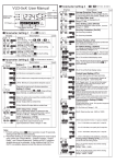
Other Products In The Range Description Code CODE-ME12 1 or 2 door controller with Ethernet connection CODE-MS12 1 or 2 door controller with Serial connection CODE-ME24 2 or 4 door controller with Ethernet connection CODE-2641 Series CODE-MS24 2 or 4 door controller with Serial connection CODE-6800 5 Amp Power supply in Metal Box Enclosure CODE-FC02 Card Distributor CODE-MF01 Mifare Card Vandal Resistant Reader USER MANUAL Product Specification Notes For Installation Packing List A For the reader cable connection to the CODE Controller, CAT 5 cable or 8 core twisted pair cable can be used. Name Qty Note CODE-2641 1 Vandal Reader User manual 1 User Documentation Screw driver 1 Φ20mm×60mm,Special for RF006 Rubber plug 2 Φ6mm×30 mm, used for fixing Self tapping screws 2 Φ4mm×28 mm, used for fixing B The reader is normally installed at the right side of the door (outside) at a height of 1.4m from the floor and 3-5 cm from the door frame, with the exit button (inside) also at a height of 1.4m off the floor. C The reader should not be installed against a metal surface. If this can not be avoided, either the metal surface should be removed, with only the fixing area remaining, or an isolation material thicker than 10cm should be placed between the reader and the metal surface. D Specification The Controller to reader length should not exceed 60 metres using CAT 5 cable Material Metal Operating Voltage 9-16V DC E Output WG 26 Please observe reader power polarity when connecting to the access controller Card type Mifare Reading Distance 2-4 cm Communication Distance 60M Idle Current <80mA Reader Parameters Operating Temperature -45ºC ~ 60ºC Operating Humidity 10%- 90% RH Reader Radio Frequency: 13-56 MHz Waterproof Conforms to IP68 Card Identification Mode: MF card Dimension 120X56X18 mm Sensing Distance: MF Card 2-4cm Reader Data Output: Wiegand 26 Bit Reading Speed: < 0.1s Wiring Connections STEP 3 STEP 2 STEP 1 Installation Procedure Remove the back cover from the keypad using the supplied special screw driver Reader Wire LED Gently pull the metal back plate cover away from the main body of the reader. • Drill 2 holes on the wall for the Self tapping screws and I hole for the cable • Put the supplied rubber bungs to into the two holes • Fix the back cover firmly on the wall with 2 Self tapping screws • Thread the cable through the cable hole, connect the wire needed, wrap unused wire with insulating tape isolated to prevent short circuit • Attach the keypad to the back cover. Colour Controller Connection Blue Connect with controller LED ”BUZ” input on controller BEEPER Yellow Connect with controller beeper D0 Green WG output line D0 D1 White WG output line D1 +12V Red Power supply +12V GND Black Power supply GND *Note To activate the sounder during the operation of the LED changing to Green, connect the Yellow Buzzer wire to “BUZ” on the controller. FAQ What should I do?: 7.1 Card not recognised by reader • Check whether the Data transmission connections of DATA 0 and DATA 1 are correct. • Check that the distance between the controller and the reader is no longer than 60 metres (Wiegand 26 bit). If so, reduce the distance between the controller and the reader. • Check the RD OK (Reader signal OK) LED ok goes green when an ID device is presented to the reader. • Check the power on the reader power wires is within 10.5v DC and 12.5v DC. 7.2 If the lock does not operate. • Check whether the connections of the readers, exit buttons and electric locks are wired correctly. • Check if the output of the relay switches and the relay operation LED switches on. • Check if the power is being switched to the lock. • If there is no switching of the relay, then check the reader and the wiring. • Check the access software programming. 7.3 If the Reader does not operate after a power down. • Please perform a controller download from the CODE Access Software