1
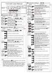
Wiring Connections
STEP 3
STEP 2
STEP 1
Installation Procedure
Remove the back cover from the keypad
using the supplied special screw driver
Reader Wire
LED
Gently pull the metal back plate cover
away from the main body of the reader.
• Drill 2 holes on the wall for the Self
tapping screws and I hole for the
cable
• Put the supplied rubber bungs to into
the two holes
• Fix the back cover firmly on the wall
with 2 Self tapping screws
• Thread the cable through the cable
hole, connect the wire needed, wrap
unused wire with insulating
tape isolated to prevent short circuit
• Attach the keypad to the back cover.
Colour
Controller Connection
Blue
Connect with controller LED
”BUZ” input on controller
BEEPER
Yellow
Connect with controller beeper
D0
Green
WG output line D0
D1
White
WG output line D1
+12V
Red
Power supply +12V
GND
Black
Power supply GND
*Note
To activate the sounder during the operation of the LED changing to
Green, connect the Yellow Buzzer wire to “BUZ” on the controller.