1
VeseNET HomePlug IP Camera Server
Model: PLA-14WCAM
User Manual
INFORMATION TO USER
Europe - R&TTE Directive
This device complies with the specifications listed below
• ETS 300-826 General EMC requirements for Radio equipment.
• ETS 300-328 Technical requirements for Radio equipment.
• EN60950 Safety Requirements for Radio equipment
-2-
Table of Contents
Chapter 1: Introduction............................................................................................................................................................................4
Overview........................................................................................................................................................4
Understanding HomePlug Networking Concept .......................................................................................4
Understanding Encryption and Security ....................................................................................................4
HomePlug Encryption and Protection Schemes ........................................................................................4
Features ..........................................................................................................................................................5
Package Contents ...........................................................................................................................................5
Requirements .................................................................................................................................................5
Wire Diagram.................................................................................................................................................6
Chapter 2: Installation.............................................................................................................................................................................7
Install HomePlug Utility ................................................................................................................................7
Hardware Installation.....................................................................................................................................9
Check Powerline Communication (Optional)................................................................................................9
Chapter 3: Configuration .......................................................................................................................................................................11
Using the IP Cam Utility..............................................................................................................................11
IP Address................................................................................................................................................12
Chapter 4 Web Manager ........................................................................................................................................................................13
Introduction..................................................................................................................................................13
Chapter 6: DVR Utility.........................................................................................................................................................................15
Main operation .............................................................................................................................................15
Menu Screen ................................................................................................................................................16
Password setup.........................................................................................................................................16
Capacity display and estimated recording hours (memory) ....................................................................17
Motion......................................................................................................................................................18
Camera .....................................................................................................................................................19
Archive.....................................................................................................................................................19
Schedule...................................................................................................................................................20
Notice – Email .........................................................................................................................................20
Network....................................................................................................................................................20
Playback...................................................................................................................................................21
Remote Operation ....................................................................................................................................21
Considerations IE Browser (or Netscape)....................................................................................................22
Chapter 7: Homeplug Configuration.....................................................................................................................................................23
Overview......................................................................................................................................................23
Diagnose a Local HomePlug Device ...........................................................................................................23
Diagnose a Network HomePlug device .......................................................................................................24
Setting Up Security on a Local HomePlug device.......................................................................................25
Setting Up Security on a Network HomePlug device..................................................................................25
Appendix A: Frequently Asked Questions...........................................................................................................................................27
Appendix B: Technical Specifications ..................................................................................................................................................29
Appendix C: Glossary ..........................................................................................................................................................................30
-3-
Chapter 1: Introduction
Overview
The HomePlug IP Camera Server operates on the HomePlug Power line Specification 1.0 standard, speed
up to 14Mbps bandwidth over home AC wiring. Since the home power lines are the most pervasive medium
in households with multiple outlets in every room, the HomePlug IP Camera Server allows remote video
surveillance without any additional wiring. It can be accessed from anywhere in the world via a standard
browser by entering the IP, account and password. With its built-in web-server, The HomePlug IP Camera
Server can stream video images directly to the Internet without have to go thru a computer. It features a
Windows-based software that allows the user to archive streaming video directly into the hard-drive. The
same software also allows the user to monitor multiple cameras on one screen.
The installation of the IP Camera Server only requires a standard browser. This makes the HomePlug IP
Camera Server compatible with any device including Mac, Windows, and Unix machines. For security, the
HomePlug devices are equipped with 56-bit DES encryption. The private home power grid plus encryption
makes HomePlug significantly more secure than competing technologies. The HomePlug IP Camera Server
is the best solution for No-New-Wires home networking. With easy Plug and Play installation, no need for
new wires.
Understanding HomePlug Networking Concept
Homeplug Networking, not to be confused with Power over Ethernet, uses your current existing or featured
power lines to transfer network data. There are existing technologies that are similar to Homeplug, such as
X10 or HPNA;
Homeplug works simply by connecting a device to two computers in two locations and respectively inside a
house or building and by plugging them into a wall outlet. It’s that simple! Now you have a network
connecting two computers. In addition, you can replace the computers with switches so that you are
connecting networks instead of computers. The process is completed within minutes with no additional
cables running everywhere and without painful cable pulling in to the ways or behind closets.
The technology behind the real working mechanism remains classified. Hopefully in the future people will
have better understanding of Homeplug.
Understanding Encryption and Security
Encryption is a method of security used to prevent intruders or unwanted access from within or outside your
network. Encryption works by using a string of letters and/or numbers as keys to encode your data. Any
computer will need to know the encryption key in order to access the data. Although the data may be
exposed to all environments, encryption will still protect your data from threats.
HomePlug Encryption and Protection Schemes
-4-
The Homeplug device uses encryption to block outside access. The key is set by using the configuration
software of the CD. By default, the protection is enabled. However, it is recommended that you change the
default encryption key. All your Homeplug devices must use the same encryption key in order for the
computers to network. Make sure that all devices are loaded with the same key
Features
•
•
•
•
Up to 14 Mbps over home power lines 100V ~ 240V
Integrated Web Server
Web-Based Remote Access Using Any Java Enabled Web Browser
Motion Detection and Email Notification Function
Package Contents
•
•
HomePlug IP Camera Server
Camera Server Utility CD, which contains;
1. HomePlug Utility: to configure HomePlug network
2. IP Cam Utility: to configure IP address information
3. DVR Software: Windows platform to monitor multiple Camera Servers.
4. Java Utility: Installed to allow user to view the IP Cam via a web browser
5. Adobe Acrobat 5.0 Reader.
6. IP Cam user manual,
Power cable
•
Requirements
Basic Requirements
•
•
•
•
•
One Ethernet based broadband Internet connection (Cable/ADSL modem or other router for web
serving ability only )
Microsoft Internet Explorer browser (V.4.75 or above with java installed)
Standard home power line wiring
One or more HomePlug Units connected to your computer. (For setup Powerline network )
CD Rom Drive
HomePlug Configuration Utility Support
•
•
•
•
Win 98 SE
Win ME
Win 2000
Win XP
* HomePlug Configuration Utility is not a requirement to install onto your computer to make the HomePlug
device to work. This utility is used for diagnostics or to modify encryption on your HomePlug device only.
-5-
Panel
Front
Back
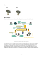
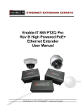
Wire Diagram
*Note* you will always need at least two HomePlug devices to create a Powerline Network
Cable/DSL/
Ethernet
Internet IP Router
IE Browser
IE Browser
Internet
HomePlug Ethernet Bridge
(PE902-EBx)
Home Electrical Wiring
HomePlug
Ethernet Bridge
HomePlug
USB Adapter
HomePlug IP Camera Server
IP Camera as a Remote Surveillance System
Once the Camera Server is installed, the user can check any of the connected IP cameras using a standard
web browser. The user can monitor and control these cameras simply by entering the IP address (set-up
required with IP CAM utility) of the Camera Server from anywhere in the world as long as there is an
Internet connection available. For instance, the user can be in Australia but is able to monitor his factory
production in China and if he likes checks on his branch office located in Singapore, all this simultaneously.
-6-
Chapter 2: Installation
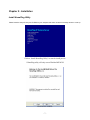
Install HomePlug Utility
Please insert the setup CD into your CD-ROM on your computer and wait a moment for the setup screen to come up.
Click on “Install HomePlug Utility” to start the install process
* HomePlug utility will only run on Win98se/ME/2k/XP
Click Next to continue.
-7-
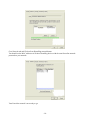
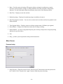
Please accept terms and continue by clicking Next.
Enter a username and an organization then continue the installation by click the Next button.
*note* the dialog might appear differently on a different operating system
Click Install button to continue the installation.
-8-
Click Finish button to complete the installation.
After completing the utility installation, a new icon will be displayed on the desktop.
Hardware Installation
Step 1:
Connect power adapter output into Camera Server socket, and plug the power input into the wall socket
Step 2:
Insure you have HomePlug Ethernet Bridge with same network password connects to your network.
You will always need at least two HomePlug devices to create a Powerline Network. In this case, you must
have other HomePlug Ethernet Bridge with same network password connects on your network, in order for
other computers on your network to configure or view this HomePlug USB Camera server.
*Note* Plug your HomePlug device directly into a power outlet on the wall. Do not plug the HomePlug
device into a UPS or power strip with surge protection. All HomePlug devices have a power filter for
protection against surges!!!!!
Check Powerline Communication (Optional)
Click the HomePlug utility icon on your desktop, you should see your IP Camera’s MAC address in the
screen
-9-
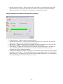
Go to Network tab and Click on Scan HomePlug network button.
You should see the MAC addresses of all other HomePlug devices with the same Powerline network
password on your network.
Your Powerline network is now ready to go.
- 10 -
Chapter 3: Configuration
Using the IP Cam Utility
Insert Setup CD into the CD-ROM driver and click on “IP Cam Utility”.
When the IP Cam Utility pops up, you can use this utility to configure the TCP/IP portion of your camera.
Click on “Find” to locate your IP Camera.
- 11 -
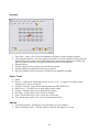
Highlight your IP Camera
Click on the “Network Config” tab
IP Address
This section sets an IP Address for Camera Server. When using HomePlug USB Camera Server for the first
time, the IP address, subnet mask and gateway will have to be set. Enter the IP Address of your choice.
Once the IP address is set, you will be able to connect to HomePlug USB Camera Server webpage from a
standard browser.
Click on “Save” after entering IP Address information.
- 12 -
Chapter 4 Web Manager
Note: You will have to use Sun Java to view the video feed on your browser. Sun Java also allows users who
are not using Windows based Operating System to view the video feed. To install Java, insert the installation
cd into your cd-rom and click on “install Java” on the main menu.
Introduction
After you have setup the hardware and set an IP address for Camera Server, you will then be able to go to
Camera Server web site to monitor and control the PC cameras. All you have to do is enter the new IP
address into any standard web browser.
1. Start the Web Brower (Netscape or Internet Explore)
2. Enter the Camera Server’s IP Address that was set earlier using the IP Camera Utility (e.g. 211.21.67.51)
and press [ENTER]
3. A login screen will appear, Click on Administrator. Default password is admin
Main Page
The Camera Server webpage main menu is divided into two sections, the selections menu on the right and
display menu on the left. The selection menu consists of the following options:
- 13 -
When using Camera Server for the first time, you must set the following to ensure that The Camera Server
works smoothly;
a.
Set the necessary parameters in the “Configuration” menu. In particular, the “Anti Flicker” under
“Camera Settings” should be set to 60Hz (change this to 50 Hz video output continues to flicker).
b.
That the camera lens is adjusted for best results.
- 14 -
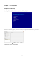
Chapter 6: DVR Utility
Insert the installation cd in your cd-rom drive then click on install DVR Utility
Double Click on the “IDSS04” icon on your desktop
The DVR Utility will Try to connect to your IP Camera but you will still need to configure the utility to
point to the ip address of your IPCamera.
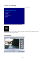
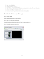
Main operation
- 15 -
1. Menu – Provides password settings, HD capacity display, estimated recording hours, motion
detection, camera parameter settings, recording schedules, short film production, and playback
functions. For more information about the operations, please refer to the following sections.
2. Date/Time – Displays current date and time
3. Monitoring image – Displays the monitoring image recorded by the camera.
4. Date/Time Segment selection – You can select a camera and record date and time for playback in the
Playback Mode
5. Time Segment display – Displays current record time segment status (10 Minutes per segment)
6. Record Button – Orange record indication means that recording is running.
7. Playback button – Is used to setup playback speed, pause and stop, and provides saving and printing
functions for specified videos.
8. Exit
9. Help – provides system requirements and operation instructions.
Menu Screen
Password setup
1. Setup Password – Enter the password in the “New Password” field and enter the same password in
the “Confirm” field. Then press the “Apply” button to finish the password setting.
- 16 -
2. Start the password Function – When you press the “Start” button, a screen appears to request your
password whenever you select the menu and you must enter your password for function setting.
When you select the “Close” button, no screen appears to request your password.
Capacity display and estimated recording hours (memory)
1. Camera Selection – Select the camera you want to operate
2. Location of Video Archive – Select the location where you want to save your video data. To select
the archive location, you must turn off the recording function.
3. HD Capacity – Displays the total capacity of the hard disk where you want to save your video data.
4. HD Capacity Available – Displays the hard disk space available currently.
5. Used Capacity – Displays the used memory space. When no more hard disk space is available, the
new recorded data will overwrite the earliest recorded data saved in the hard disk so that the
recording may continue without interruption.
6. Estimated Recording Hours (ERH) – Displays the estimated hours required for the system to perform
recording for each round (i.e., the estimated hours the saved video data will remain in the HD.) if the
ERH is small (e.g., less than two hours) due to the limited available HD capacity. It is recommended
that the FPS Settings of the cameras should be set to 1 or 0.
- 17 -
Motion
1. Camera Selection – Select the camera you want to operate.
2. Displays the monitoring image recorded by the camera.
3. Movement detection button – includes “On” and “Off” modes. In the “On” mode, the screen shows
red grids and recording time segment (refer to “time segment display” in the main screen) changes
from green to red when the system detects any moving object.
4. Monitoring Area – Users can setup a monitoring area by selecting global monitoring or defining a
monitoring range.
5. Add and Delete – If you select self-definition, press and hold the left mouse key to drag a green zone
as a monitoring region on the monitoring screen of the camera. Then click the “Add” button to add a
new definition. You may delete the self-defined zone by clicking the “Delete” button.
6. Sensitivity – Adjust the movement detection sensitivity. The sensitivity declines when you move
upwards; it increases when you move downwards.
7. Apply Self-defined Sensitivity and Default – Finish sensitivity settings by clicking the “Apply”
button when you setup the self-defined sensitivity successfully. Press the “default” button to use the
default sensitivity of the system.
- 18 -
Camera
1. Camera Selection – Select the camera you want to operate.
2. FPS Settings – Provides two modes for setting up recording frames per second: The normal mode
and the event mode. The former is used to set up normal recording frames. The latter is used to setup
the recording frames when any moving object is detected (The movement detection switch should be
turned on).
3. URL – Key in the IP address and the password of the selected camera.
4. Attribute – Is used to adjust the camera’s contrast, brightness, color, and saturation.
5. Image Quality – Is used to adjust recording quality
6. Default – Restores the default value of the system.
7. Apply – Apply the attribute and image quality altered by users.
8. Tag – Specify the tag name for the selected camera.
Archive
1. Camera Selection – Select the camera you want to operate
2. Display Archives – The length for each record is one hour.
3. Delete Archives – Select the archive to be deleted from the archive list and press the delete button to
delete the archive.
4. Short Film Production – Convert the archive to a movie file and save in the Mpeg4 format.
5. Select Date – Select the date and time segment of the record to be converted
6. Select Time Segment – Each box in the window represents 10 minutes. Add 10 minutes more by
pressing “Add” on the left side. Delete 10 minutes more by pressing the “Delete” on the left side.
The “Add” and “Delete” buttons on the right side have the same functions.
7. Start – Press the “Start” button and select a file path and name. Start to create “avi” file pressing the
“Confirm” button.
8. Forced Stop – Stop the movie file that is under creation. The movie file that is already created will be
reserved.
9. Time Elapse – Time elapse for the creation of a movie file.
10. Frames Handled – Represents the amount of frames processed.
11. Remaining – Indicates the remaining time required to finish the process (Unit: minute)
- 19 -
Schedule
1.
2.
3.
4.
5.
6.
Time Table – Select a day or Days from Monday to Sunday to Setup recording schedules.
Time Segment Selection – One time segment is one hour, so one day amounts to twenty-four time
segments. In the above figure, the red bar indicates the selected time segment for recording. The
system will then execute the recording function based on the selected schedule.
Schedule Switch –
All time segments on the same day are selected for recording
All time segments recorded on the same day are deleted.
Apply the schedule of the current day to all other days arranged for recording.
Notice – Email
1. Sender
2. Receiver – indicates the Email addresses of a receiver. Use”;” to separate each address when
multiple receivers are to be entered.
3. Account / Password – Enter the account and password of the SMTP server.
4. SMTP Server – The SMTP server email address of the vendor.
5. Contents – Indicates that users can define Email contents.
6. IP Change – Sends email to users when IP is changed
7. Event – Sends email to give users a notice any event occurs
8. Test – Sends email to give users a notice by pressing this button.
Network
1. Current Site location – Displays the current IP address of your computer.
2. Start the Web Page Server – Decides whether to start the web page server or not.
- 20 -
Playback
1. Preview – Displays the image of each time segment within one hour (10 minutes per time segment).
You can select an image of a specific time segment for playback by clicking the left mouse key.
2. Back – Return to the monitoring screen by pressing the “Back” button.
3. Playback – Play the archive of the time segment you select.
4. Stop – Stop playing the archive.
5. Fast forward – Provides 2X, 4X and 8X speed adjustment. Select different playback speed by press
the “Fast Forward” button repeatedly.
6. Pause – Suspends playing immediately by pressing the “Pause” button.
7. Print – Press “pause” and then “Print” to print the current screen when you playback the archive.
8. Save – Press “Pause” and then “Save” to save the screen as a JPEG picture when you playback the
archive.
9. Date and Time Segment selection – Displays the date and time segment for playback or the segment
for the current recording.
10. Short Film Production – Calls the Short film Production Program based on the selected time segment
11. Full size playback (default) or fit margin playback.
Remote Operation
Remote Monitoring Program (Client.exe)
Main Screen:
1. Connect to – Enter Server IP address
2. Connect/ Disconnect – Enter the specified IP address and press “Connect” to receive the remote
screen data. Press “Disconnect” to abort the connection to the remote device.
3. Recording – Record the remote image in the hardware of the local machine.
4. File – Select the local video file to playback the archive you select.
Playback:
- 21 -
1.
2.
3.
4.
Stop – Stops the playback
Playback – playback archives
Fast Forward – Increases playback speed.
Pause – When the Pause function is working, the zooming function is enabled. For more information
about the zooming, refer to the next section.
5. Previous time segment – Playback the archive of the lat time segment
6. Next time segment – Playbacks the archive of the next time segment
Considerations IE Browser (or Netscape)
Step 1: Security settings
Set the internet security settings to the lowest level.
Step 2: Enter an IP address or a domain name.
Enter the IP address or a domain name and press “Enter” to connect to the server.
Step 3: Choose the camera you want to view.
- 22 -
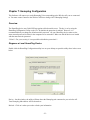
Chapter 7: Homeplug Configuration
This Software will connect you to the Homeplug Unit corresponding to the Wireless AP you are connected
to. You must ensure Connect to the Wireless AP first to change ANY Homeplug Settings
Overview
The HomePlug device uses 56-bit DES encryption to block outside access. The key is set by using the
HomePlug Configuration Utility on the CD. By default, the protection is enabled. However, it is
recommended that you change the default network password. All your HomePlug devices must use the
same network password in order for the computers to be networked. Make sure that all devices are loaded
with the same network password.
**Note**: For your security, it is not possible to disable the protection!!!
Diagnose a Local HomePlug Device
Double click the HomePlug Configuration utility icon on your desktop to open this utility show in the screen
below
Device – On this window, the utility will then detect the Homeplug unit connected to your wireless AP.
Your Homeplug Mac address will be shown here.
Refresh – Click on it when you need to refresh your information
- 23 -
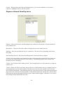
Connect – When you have more than one Homeplug device, you can select which device you want to
connect to. Highlight the device and click connect.
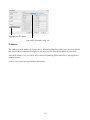
Diagnose a Network HomePlug device
Network - This tab will show all your Homeplug devices connected to the network. Scan the network for
newly added devices.
Mac Address – The device ID or Mac Address is displayed on the tab to identify the unit
Data Rate – Show the speed that this device is connected at. This data will vary depending on the Power
line quality.
Scan HomePlug Network - Rescan the HomePlug network, and refresh with any changes.
**Note** Only units with the same Network Password will be shown, please check that first, to make sure
they all have the same network password (Case sensitive). All HomePlug products come with the same
network password: “HomePlug”.
**Note** If a Unit shows MAC Address of all 0’s, this unit might not have a solid connection, or might not
connect at all.
**Note** If there are Units in your home, that you do not see in this Network scan, try to unplug all devices,
and plug them back in (Only do this with the Units that you do not view in the network screen, you don’t
have to do this with all units. If the problem persists, try to move the unit closer to this current unit (adjacent
plugs on the same wall socket is most preferable). If the problem still persists and that unit is still not shown
on the network, then the unit might be defective please contact technical support. Otherwise if you view the
unit working, distance might be the only issue.
- 24 -
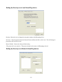
Setting Up Security on a Local HomePlug device
Security- Allows the user to change the encryption setting on the Homeplug device.
Set Local – Enter the password into the Network Password Box and click on Set Local. This will change its
password to the local device only.
Restore Default – Restore the factory default setting.
*The password is case sensitive. This password must be the same on all Homeplug devices*
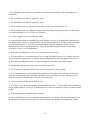
Setting Up Security on a Network HomePlug device
- 25 -
The Advanced Tab will allow users to use one primary computer to control the Network Password of all
Homeplug units on the Powerline network. First Find the Device Password located on the bottom of each
device. Enter this ID into the Device Password area. Click Add. This Device Password will then appear in
the Remote Passwords Box. Add all the Device Password for each unit in your house. You can then change
the password remotely from one computer. This will allow you to change the password from one computer,
instead of changing the password individually.
**Note** The Device Password is unique for EACH HomePlug device. To use this you will need to input
the Device Password for each unit.
- 26 -
Appendix A: Frequently Asked Questions
Still having trouble setting up this HomePlug Camera, please read the following questions and answers to
solve your problems with the router.
Q: I can’t seem to log onto the Web Manager’ page or the DVR software can’t see any Camera on the
network?
A: If you have already followed the instructions from the manual and still can’t log onto it:
Please do a power reset of the HomePlug IP Camera. For example: Unplug it from the wall outlet for few
minutes and Plug it back on.
Check the other HomePlug device on your network, make sure it plug in and work properly.
Make sure you have the same subnet mask IP between the computers and the HomePlug Camera
Try to ping your Camera’s IP. Make sure you get Reply from it.
Use the Homeplug utility to scan for this HomePlug Camera.
All HomePlug units must have the same network password to communicate each other. The default network
password on all HomePlug units is “HomePlug”
Q: Why is it that my Homeplug units do not find each other using the HomePlug configuration utility?
A:
Plug them both into the same power outlet, and then make sure the LED light on the units light up. If the
lights do not turn on, try another power plug.
Make sure that the units are not plugged into a power surge protector, or an extension cord (sometimes the
signal cannot be sent through these devices).
Power-cycle the units by unplugging the units and wait a couple of minutes and then plug the units back in.
Check the encryption on the Homeplug units. To change the encryption, you need to connect them directly
to the computer. The default encryption on the Homeplug units is “HomePlug”.
Q: How can I protect my network from invaders? How is Homeplug secure?
A: HomePlug uses a 54-bit DES encryption, which is very difficult to decode. The Homeplug signal also
stops at a change of phase on the mains – it’s therefore very unlikely your neighbors can detect your
Homeplug signal.
Q: What’s the speed of HomePlug operate over a standard home power line network?
A: HomePlug operates up to 14 Mbps bandwidth over a standard home power line network
Q: What’s the Estimated Range of HomePlug?
A: Approximately 300 meters in wall power lines (one household).
Q: Will HomePlug work in any home?
A: Any home with copper wiring built-in, since some of the older houses built before 1950 might have older
wiring, it may not work in these instances.
Q: Will HomePlug signal pass through circuit breakers?
- 27 -
A: Yes, HomePlug signal will have no problem passing through circuit breakers but not through power
transformers.
Q: Does HomePlug work with AC input 100 – 240V?
A: Yes, HomePlug works with AC input 100 – 240V.
Q: Does HomePlug cause any interference with other my other home networking device?
A: No, HomePlug operates in a different frequency band than other power line control devices and can coexist with technologies as X-10, CEBus, and LONworks.
Q: Can my neighbor receive my HomePlug signal?
A: It is possible but extremely improbable that your neighbor can receive your HomePlug signal between
two adjacent homes. However, just to be 100% sure you should enable the 56-bit DES security encryption
on your HomePlug Device. To do that, you must run the HomePlug Configuration Utility on each
HomePlug device in your Powerline network. This will only allow computers with the same security
password to be able to receive information.
Q. How many HomePlug devices do I need to setup a Powerline network?
A. You must need two or more HomePlug devices to setup a Powerline network. For example, you have
one HomePlug AP connect with your network, and one HomePlug Ethernet bridge plug in with your pc.
Q. How many HomePlug Ethernet device that I can install into one same Local Area Network?
A. Recommend install up to 16 on one same network password LAN.
Q. Can I connect my Homeplug USB Camera Server to an extension cord or an UPS?
A. Yes, HomePlug devices can be plugged onto extension cords, but please note that this will reduce the
Powerline signal strength of the connection. Sometime it may even reduce it to zero! Please use a wall
outlet if it’s possible. HomePlug devices do not work with a UPS.
Q. Can I use other HomePlug brands with this one?
A. Yes. However, it’s not recommended to mix HomePlug units with
other brands as the internal board
may be slightly different. As long as all HomePlug devices under the HomePlug 1.0 Specs, then they should
be OK.
Q. Will anything happen if lighting strikes my house?
A. All our HomePlug devices have lighting protection build-in. It will only cause the internal board of the
HomePlug device to short circuit. However, it will not damage your computer or anything plug in with it.
- 28 -
Appendix B: Technical Specifications
-
Network Interface: HomePlug Powerline
Installation: Plug-and-Play
Certifications: HomePlug Powerline Specification 1.0
Housing: Plastic
Built-In Web Server
Support Any Java-Enabled Web Browser
0.30um CMOS sensor - 5.04um x 5.04um active square pixel
VGA resolution, total pixel array size is 652x492, and 652x488 pixels are active
1/4 inch optical format, Bayer RGB color filter array Micro-lens for high sensitivity
10-bit Digital Image Signal Data Bus
Max Frame Rate: 10 frames at 25Mhz Master Clock (VGA)
Low fixed pattern noise by correlated double sampling
Auto black level compensation
Lens vignetting compensation
Advanced color interpolation, color adjustment function and 2D edge enhancement
Auto bad-pixel cancellation
Hardwired super-resolution filter
Real time baseline JPEG compression
Operating temperature: 0C to 45C
Operating humidity: 10% to 90% non condensing
Frequency Band: 4.3 MHz - 20.9 MHz
Modulation: OFDM Modulation
Encryption: 56-bit Data Encryption with Key management
LED display: Reset, Link, RX, TX, Power, Homeplug
Software utility: IP-Cam utility, DVR setup utility, JAVA and Homeplug Utility: Device
detect/diagnostic, Network Password setup for local and Remote device Windows 2000, ME, NT, or
XP for initial setup
Certification: FCC, CE
- 29 -
Appendix C: Glossary
Default Password
A password set by the manufacturer that is unique to each device and is used to generate a Default
Encryption Key (DEK). The DEK is used only for the purpose of encrypting management commands that
change the NEK so that the NEK is never sent in the clear over the Powerline.
DHCP
Dynamic Host Configuration Protocol - a method in which IP addresses are assigned by {the} server
dynamically to clients on the network. DHCP is used for Dynamic IP Addressing and requires a dedicated
DHCP server on the network.
Direct Sequence Spread Spectrum
This is the method the wireless cards use to transmit data over the frequency spectrum. The other method is
frequency hopping. Direct sequence spreads the data over one frequency range (channel) while frequency
hopping jumps from one narrow frequency band to another many times per second.
Encryption
A security method that applies a specific algorithm to data in order to alter to alter the data’s appearance and
prevent other devices from reading the information.
Encryption Key (EK)
64-bit pattern generated by a key derivation function. An EK is used in an encryption algorithm to add
security to transmissions between HomePlug devices in a logical network.
Ethernet
Ethernet is a 10/100Mbps network that runs over dedicated home/office wiring. Users must be wired to the
network at all times to gain access.
Gateway
A gateway is a hardware and software device that connects two dissimilar systems, such as a LAN and a
mainframe. In Internet terminology, a gateway is another name for a router. Generally a gateway is used as a
funnel for all traffic to the Internet.
Local Area Network (LAN)
A LAN is a group of computers, each equipped with the appropriate network adapter card connected by
cable/air, that share applications, data, and peripherals. All connections are made via cable or wireless
media, but a LAN does not use telephone services. It typically spans a single building or campus.
Logical Network
Two or more HomePlug devices that share a common Network Encryption Key (NEK) and that
communicate with encrypted transmissions
Network
A network is a system of computers that is connected. Data, files, and messages can be transmitted over this
network. Networks may be local or wide area networks.
Network Password
A password set by the user that generates the NEK and defines the user’s logical Network.
- 30 -
Powerline Networking
Data transmission over Power lines.
Protocol
A protocol is a standardized set of rules that specify how a conversation is to take place, including the
format, timing, sequencing and/ or error checking.
RJ-45
A connector similar to a telephone connector that holds up to eight wires used for connecting Ethernet
devices.
Router
Protocol-dependent device that connects subnet works together. Routers are useful in breaking down a very
large network into smaller sub networks; they introduce longer delays and typically have much lower
throughput rates than bridges.
Static IP Addressing
A method of assigning IP addresses to clients on the network. In networks with Static IP address, the
network administrator manually assigns an IP address to each computer. Once a Static IP address is
assigned, a computer uses the same IP address every time it reboots and logs on to the network, unless it is
manually changed.
Transmission Control Protocol / Internet Protocol (TCP/IP)
TCP/IP is the protocol suite developed by the Advanced Research Projects Agency (ARPA). It is widely
used in corporate Internet works, because of its superior design for WANs. TCP governs how packet is
sequenced for transmission the network. The term “TCP/IP” is often used generically to refer to the entire
suite of related protocols.
Tx Rate
Transmission Rate
Wide Area Network (WAN)
A WAN consists of multiple LANs that are tied together via telephone services and / or fiber optic cabling.
WANs may span a city, a state, a country, or even the world.
- 31 -