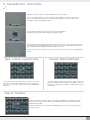
1
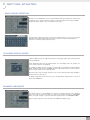
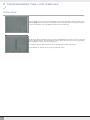
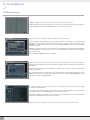
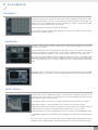
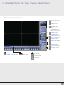
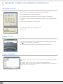
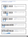
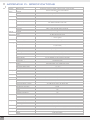
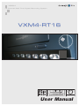
MPEG4
16 Channel Real Time Digital Recording System
VXM4-RT16
!
DISPLAY
SEQ
HOLD
PANIC
±
ZOOM
LOCK
RW
.
ZOOM
OUT
ARCHIVE
+
FF
.
ZOOM
IN
User Manual
PTZ
SETUP
SEARCH
PWR
REC
NET
1
2
3
4
5
6
7
10
11
12
13
14
15
16
IRIS
FOCUS
RETURN
ENTER
8
9
NEAR
FAR
CLOSE
OPEN
CONTENTS
Before Installing
Key Features
Front Panel Description
Rear Panel Description
Getting started
Connect and switch on
Basic Mouse Operation
Configuring the live display
Choosing Display Modes
Running a sequence
Digital zoom
Playback
Search
Panorama 1
Panorama 2
Smart Search
Archiving
New Archive
Managing Existing Archives
Telemetry Control
Key lock function
Panic recording
Shut down
Configuring the VXM4-RT16
Camera
Title
Colour
PTZ
Covert / OSD
Alarm / Event
Sensor
Video Loss
Motion Detection
Storage
User Defined
Alarm / Event : Event Action
Digital Out
Email Notification
Remote Client Notification
Video Pop-Up
Buzzer
Display
Screen Template
Main Display Sequence
Spot #1, #2, #3, #4 Display Sequence
Audio
User
User Group
User
Network
Configuration
Email Server
1
2
3
4
5
5
6
6
6
7
8
8
10
10
10
11
11
11
12
12
12
12
13
13
13
13
13
14
15
15
15
15
16
16
17
17
17
17
18
18
18
18
19
20
20
20
20
21
21
21
22
CONTENTS
System
Information
Date / Time
Update
Storage
Operation
Utility
Disk View
Entering the Recording Menu
Record Mode
Normal Record
Schedule
Intensive Record
Panic Record
Connecting to the VXM4 remotely
Install the software
Remote client controls
Remote client setup
Create a connection group
Enter VXM4 details
Additional configuration
Using the remote client
Connect to a VXM4 group
Live display modes
Saving to AVI file
Viewing events
Telemetry control
Audio monitoring
Audio talkback
Triggering alarms
Connection status
Remote client playback controls
Searching for footage
Controlling playback
Audio monitoring
Archiving footage
Backup player
Taking a snapshot
Event search
Print an image
Viewing events
Remote VXM4 setup
Entering setup
Loading and saving
Appendix A: The Archive Set
Appendix B: Configuring a Netgear DG834
router for use with the VXM4
Appendix C: Connecting external devices
Appendix D: Specifications
Notes
22
22
22
22
23
23
23
23
24
24
24
25
26
26
27
27
28
29
29
29
30
31
31
31
32
32
32
33
33
33
33
34
34
34
34
35
35
35
36
36
36
37
37
37
38
39
42
43
44
BEFORE INSTALLING
•
Installation should be carried out only by qualified personnel and in accordance with any
electrical regulations in force at the time.
•
The DVR must be placed on a stable surface or mounted in an approved cabinet. Adequate
ventilation must be provided, taking particular care not to block any of the air vents on the DVR.
1
•
Adequate protection against lightning strikes and power surges must be installed to prevent
damage to the DVR.
•
Any safety warnings on the DVR and in these instructions must be adhered to.
•
If cleaning is necessary, shutdown the DVR and disconnect power first. Use a soft dry cloth only –
never use any abrasive cleaners.
•
Do not attempt to service or repair the DVR as opening or removing covers may expose
dangerous voltages or other hazards. Refer all servicing to qualified service personnel
KEY FEATURES
REAL TIME 400FPS RECORD RATE
HIGH RESOLUTION VGA MAIN MONITOR OUTPUT
INTUITIVE ALARM HANDLING WITH USER DEFINED LINKED EVENTS
SIMULTANEOUS LIVE AND PLAYBACK VIEW.
UP TO 2TB INTERNAL STORAGE.
USB MOUSE CONTROL
DVD-RW, USB AND NETWORK ARCHIVE
SMART SEARCH PLAYBACK.
THUMBNAIL SEARCH
SNAPSHOT EMAIL
FULL REMOTE CONFIGURATION
USER DEFINABLE SPOT / MAIN MONITOR MULTI SCREEN DISPLAYS.
ARCHIVE TO INTERNAL STORAGE.
2
FRONT PANEL DESCRIPTION
SYSTEM CONTROL KEYS
LOCK
Locks the front panel buttons
POWER BUTTON
DISPLAY
Selects various display
modes in live display and
playback
SEQ
Calls the currently defined
sequence mode
PANIC
Selects panic recording mode
ZOOM
Selects digital zoom mode in
live display
SHUTTLE WHEEL
Used to quickly adjust
playback speed and
direction. Also used to control
camera zoom when in PTZ
mode, and digital zoom level
in live display
ARCHIVE
Displays the archive menu
PTZ
Selects PTZ mode in live
display
JOG RING
When playback is paused,
used to move footage
forwards or backwards, frame
by frame
SETUP
Displays the setup menus
SEARCH
Displays the search menu
HOLD
Locks the current function of
the SHUTTLE WHEEL so it
can be released
!
DISPLAY
SEQ
PANIC
LOCK
ARCHIVE
SETUP
SEARCH
HOLD
±
ZOOM
RW
.
ZOOM
OUT
+
PTZ
PWR
REC
NET
1
2
3
4
5
6
7
10
11
12
13
14
15
16
FF
.
ZOOM
IN
IRIS
FOCUS
RETURN
ENTER
8
9
NEAR
USB ports
Supports a wide
variety of USB
memory stick for
archive, system
setting backup and
firmware upgrade.
An additional USB
port is also
provided on the
rear panel
CURSOR KEYS,
ENTER and
RETURN buttons
Used for navigating
setup menus, search
and archive screens.
Also used when the
VXM4 is in PTZ mode
CHANNEL SELECTION
BUTTONS
Used to display individual
channels in live display and
playback (page 6 & page 8)
Also used to enter numeric
passwords for the various
login screens
FAR
Increases reverse playback
speed
Selects reverse playback
Pauses / resumes playback
Selects forward playback and
also accesses the instant
playback feature
Increases forward playback
speed
3
CLOSE
OPEN
REAR PANEL DESCRIPTION
CAMERA INPUTS and LOOP
OUTPUTS
COMPOSITE AND S-VIDEO MONITOR
CONNECTIONS
SPOT MONITOR
OUTPUTS
Connect up to 16 camera inputs.
Secondary monitor outout to be used in
conjunction with the main VGA monitor output
Up to 4 spot
monitors can be
connected as
necessary
Loop outputs can be used for
connection to other equipment
1
2
3
4
5
6
7
8
9
10
11
12
13
14
15
16
1
2
3
4
5
6
7
8
9
10
11
12
13
14
15
16
SPOT 1
SPOT 2
SPOT 3
SPOT 4
Connection to
external
telemetry
devices, panic
button and
alarm reset
VIDEO IN
ALARM OUT
ALARM IN
AUDIO IN
AUDIO IN 2
AUDIO IN 3
AUDIO IN 4
AUDIO OUT
A11 A12 A13 A14 GND A15 A16 A17 A18 GND A19 A20 A21 A22 GND A113 A114 A115 A116 GND
CAUTION
RISK OF ELECTRONIC SHOCK
DO NOT OPEN
AUDIO INPUTS
& OUTPUTS
Up to 4 audio inputs
and one audio
output can be
connected as
necessary
ALARM INPUTS
Up to 16 alarm
inputs can be
connected and
configured as high
or low inputs with
common ground
!
ALARM
OUTPUTS
Up to 16 alarm
outputs can be
connected and
configured as high
or low outputs with
common ground
A01 A02
A05 A06 A07 A08 GND A09 A10 A11
USB
VGA
485-
485+
ARI
A03 A04 GND
GND
AUDIO IN / OUT
MONITOR OUT
PANIC
LOOP OUT
100-220V AC
A12 GND A013 A014 A015 A016 GND
RS-232C
NETWORK 1
VGA
SERIAL PORT
LAN
VGA main
monitor
connection to a
PC monitor or
plasma screen.
SERIAL port for
connecting external
RS-232 devices
LAN
connection
to a router
or internal
network
4
GETTING STARTED
PLEASE NOTE: ALL NECESSARY CONNECTIONS MUST BE MADE BEFORE APPLYING POWER TO THE
VXM4-RT16!
The VXM4-RT16 is pre-configured with the following settings:
25FPS continuous recording rate per channel at CIF (352 x 288) resolution and highest image quality.
•
Time and date set to correct local time
•
Audio inputs 1-4 assigned to video channels 1-4 respectively
•
Telemetry devices set to PELCO-D, 2400 Baud
•
Based on average image recording, the above settings will provide around 6 days recording on 1TB of storage
before the footage starts to be overwritten.
CONNECT AND SWITCH ON
•
Connect up to 16 CAMERA INPUTS as necessary. The VXM4-RT16 also has LOOP OUTPUTS so that any
signals can be fed to other equipment if required. Termination is automatically set by the VXM4-RT16 depending
on connection type
•
Connect a VGA monitor to the VXM4-RT16 using the VGA connection
•
Connect a USB mouse to either the front or rear USB sockets
•
Connect power to the VXM4-RT16 and press the POWER BUTTON on the front panel to begin operation.
The VXM4 startup screen detects and checks the status of hard drives and the
DVD-RW drive. After startup diagnostics are complete, the operator must logon to
the system.
The default user name is 'ADMINISTRATOR', no password. Using the mouse,
click OK to logon to the system
The VXM4-RT16 begins normal operation and shows the default display of all 16
channels. A blue square and letter 'T' in the top left of each channel display shows
that the channel is recording in Timer mode
3 status windows (Live System Info, Live Log and Live Alarm) show the current
operating status of the DVR - any of the windows can be closed by clicking 'X' at
the top right of the window.
To display a window again, move the mouse cursor to the bottom left of the screen
and choose which window to display from the popup.
5
GETTING STARTED
BASIC MOUSE OPERATION
All features of the VXM4-RT16 can be controlled quickly and easily using just the mouse. At the
live display screen, click the right mouse button to call up the various menu options available.
Click the left mouse button to choose a particular menu option
In many instances during operation, text entries are required. In this case, an on screen virtual
keyboard can be displayed by double clicking the relevant text entry box and picking the
characters or numbers required using the mouse.
CHOOSING DISPLAY MODES
5 different display modes are supported and can be changed by calling up the main menu and
choosing 'DISPLAY'
Under 'DISPLAY TYPE' select the required layout. For each display mode, the operator can
choose which cameras to be displayed.
For example, to display cameras 4,7,13 & 15 in quad mode, select quad mode under 'DISPLAY
TYPE'. Click the number 4 in the 'CHANNEL' box to the right and then click one of the 4 squares
below to assign camera 4 to the desired position.
Repeat the above steps to assign cameras 7,13 & 15 to the desired positions and click 'OK' to
exit back to the live view screen
To display a particular camera full screen, press the appropriate channel button on the front
panel of the VXM4-RT16
RUNNING A SEQUENCE
The default sequence on the VXM4-RT16 is cameras 1-16 displayed in full screen, switching
every 5 seconds. To begin this sequence, call up the main menu and choose 'SEQUENCE
PLAY'. To stop the sequence, call up the main menu again and choose 'SEQUENCE STOP'.
Further complex sequences can be defined in the VXM4-RT16 display setup
6
CONFIGURING THE LIVE DISPLAY
DIGITAL ZOOM
Each live display channel can be zoomed digitally by up to 8 times. Call up the main menu and choose
'DIGITAL ZOOM'. The small window at bottom right shows the full image with a white square to indicate
zoom level and position. The main display area shows the zoomed portion.
Roll the mouse wheel forwards to increase zoom level and backwards to decrease. To move the zoomed
image to different positions, click and hold the left mouse button when the cursor is in the main display
area and drag the image to show the desired portion.
To change the channel, right click and choose the desired channel from the popup menu.
To exit digital zoom, click the exit icon at the top right of the screen
7
PLAYBACK
SEARCH
To search for recorded footage, call up the main menu and choose 'SEARCH'. Click 'OK' to logon as the
default ADMINISTRATOR' user, no password.
Note: Any other user can also search for recorded footage if this function has been assigned in
the user setup menu
NORMAL SEARCH
Normal search uses either a basic calendar / timeline or event based search to quickly retrieve footage.
In playback search, the calendar on the left shows the current month. Days highlighted in green have
recorded footage.
The timeline at the bottom of the screen shows a 24 hour status of all channels for the selected day.
The timeline is colour coded to indicate the type of recorded footage (Timer, Alarm, Motion, User
Defined or Panic).
Using the mouse, pick the required day from the calendar and then drag the timeline cursor to the
required time. The timeline display can be expanded or reduced by clicking the + & - buttons at the top
left of the timeline display.
As the timeline cursor is dragged and released, the actual selected time is displayed under the
calendar.
Once the correct time has been chosen, click the forward play button under the calendar to begin
playback. All 16 channels begin playback within the normal search screen.
During playback, the operator can choose to display a live view window instead of the calendar by
clicking 'Live view' above the calendar.
To choose a different screen display during playback, click the SCREEN FORMAT drop down option
below the calendar and pick the desired option.
8
PLAYBACK
SEARCH continued
In addition, playback can be switched to full screen by clicking the full screen icon.
To adjust playback in full screen mode, move the mouse to the bottom right of the screen to display the
playback navigation controls. Click RETURN to exit to the normal search screen
During normal search, still image snapshots and live archives can be taken.
To take a snapshot, pause playback at the desired time and click the snapshot icon. Using the virtual
keyboard, enter a tag name to identify the snapshot and also a memo if desired. Then either click
RESERVE to save the snapshot in the archive area or START BURNING to save the snapshot directly
to USB stick or DVD
In addition, the snapshot can be sent as an email. Use the virtual keyboard to enter a valid email address
and click SEND. Note - an email server must be correctly configured in the VXM4-RT16 network setup
for this option to work
Note: the SELECT SCREEN option is not available
To archive footage, choose the desired start position and click the archive icon. Use the virtual keyboard
to assign an archive tag name and a memo if desired. Tick which channels to include in the archive, and
click START
Click the forward play button to begin playback / archiving - the archive icon turns red to show that
archiving is in progress.
Once the desired amount of footage has been reviewed, click the archive button again and then click
FINISH. The footage can be burnt directly to DVD or USB stick by clicking START BURNING or stored
in the archive area by clicking RESERVE
To search the event log, click the Log option above the calendar and pick from the calendar to display
log entries for a particular day.
The event log can be refined by ticking or un-ticking the boxes below the calendar to remove events from
the log display. Click on the magnifying glass icon to refresh the event log.
To playback a particular event, double click its entry in the log. The display returns to the normal playback
search screen and playback of the selected event begins.
To exit normal search and return to live view, click the X button at the top right of the screen
9
PLAYBACK
PANORAMA 1
Panorama 1 search allows the operator to review a single channel of playback footage frame by frame.
Using the calendar / timeline method, choose the desired start position and click on forward play. The
playback screen shows playback frame by frame and allows the operator to quickly identify subtle
changes in the footage and at what time they occurred.
Snapshot and archive modes can be used as described earlier.
Tip: For effective snapshot archiving, adjust playback speed to below 1x to make it possible to pause
playback at the exact frame required
PANORAMA 2
Panorama 2 search allows the operator to quickly review a single channel of playback over a period of
either 24, 12, 8, or 4 hours
Using the calendar only, choose the desired day to review. Then, select 4, 8, 12 or 24 hour from the range
and click on forward play. The playback screen shows 8 different playback windows, each showing a
particular time segment (for example, for a 24 hour range, 00:00 - 03:00, 03:00 - 06:00 and so on).
At the top of each playback window, a timeline is displayed to indicate the presence of recorded footage
within that particular time segment. For any of the playback windows, use the mouse to drag the timeline
cursor to any required time. As one timeline is adjusted, the other 7 playback windows automatically
adjust.
Only snapshot mode is available in Panorama 2 search. During snapshot archiving, use the SELECT
SCREEN dropdown to choose which one of the 8 playback windows the snapshot should be taken from.
SMART SEARCH
In smart search mode, the VXM4-RT16 analyses a selected period of playback footage and can be
configured to detect either instances of motion detection or times when particular objects were removed
from or added to a scene (museum search)
Choose which channel to review, the type of search required and the start and end time to analyse.
Adjust spatial sensitivity - a lower value will give a more sensitive search for object detection.
Adjust temporal sensitivity - this is the time interval at which footage is analysed. For example, a temporal
sensitivity setting of 20 means the selected time range is analysed once every 20 seconds.
On the main image, use the mouse to drag and select the area to analyse, and click SEARCH to begin.
The VXM4-RT16 analyses the selected time period and displays a log of all motion or museum detected
events.
Once the search is complete, each entry in the log can be double clicked to begin playback from that
particular event time. During playback, snapshot and archive modes can be used as described earlier.
10
ARCHIVING
As well as allowing the operator to archive selected footage to DVD or USB stick, the archiving section
of the VXM4-RT16 can also be used to review information about snapshots and archives taken during
playback.
Call up the main menu and choose 'ARCHIVING' to display the main archive screen.
NEW ARCHIVE
To create a new archive, use the virtual keyboard to enter an archive tag name and pick the desired start
and end time to archive.
Note: there are two timeline cursors representing the start time and end time and these can be quickly
dragged using the mouse.
Tick the boxes for LOG, TEXT and REC INDEX TABLE if this information should also be included on the
archive set.
At the left of the timeline, choose which of the 16 channels should be included in the archive set, and use
the virtual keyboard to enter a memo if the circumstances of the archive need to be described in more
detail.
Finally, click the QUERY button to display the estimated size of the archive set and the start and end time.
If incorrect values have been chosen, click the RELEASE button to reset all values and then repeat the
above steps to define a new archive set.
Once the archive set is complete, the operator can choose either to burn directly to DVD or USB by
clicking the burning icon, or, the archive can be saved in the archive area for future use by clicking the
reserve icon.
MANAGING EXISTING ARCHIVES
From the archiving menu, choose the backup data management icon to display all previous archive sets
and snapshots.
To display detailed information about an archive or snapshot entry, highlight it and click the info icon.
To delete an archive or snapshot, highlight it and click the delete icon. The VXM4-RT16 prompts for
confirmation.
Finally, a selected archive or snapshot can be burned to DVD or USB by highlighting it and clicking the
burn icon.
11
TELEMETRY CONTROL
Call up the main menu and choose PTZ to display the PTZ control window.
Choose the required camera to control from the drop down CAM list, and then use the mouse to
click on the directional arrows to move the camera as required. Zoom, Focus and Iris can be
controlled be clicking the appropriate buttons.
The speed that the camera moves when controlled can be adjusted by
clicking the parameter button and changing the appropriate values.
For an alternative control method, by clicking the mouse icon, the mouse can be used to directly control
the camera by clicking and dragging the mouse across the screen in the desired direction. Zoom level
can be adjusted by clicking and then rolling the middle mouse wheel.
Click the exit icon at the top right of the screen to exit mouse control and return to the standard PTZ
controls
.
KEY LOCK FUNCTION
To lock the front panel and disable mouse control, press the key
lock button. To unlock, either click anywhere on the live display, or
press the key lock button again, and enter the administrator
password
PANIC RECORDING
To activate panic recording, press the panic button on the front
panel. All standard recording settings are overridden in favour of
the panic record settings. To exit panic recording, press the panic
button again.
SHUT DOWN
Only users with system shutdown rights can shutdown the VXM4-RT16. To shutdown, press the
power button on the front panel and enter the appropriate username and password where
prompted and click OK.
Once the shutdown process is complete, the VXM4-RT16 beeps once to indicate that power can
be safely removed.
12
CONFIGURING THE VXM4-RT16
Basic setup procedures
All VXM4-RT16 setup is configured using the mouse and the virtual keyboard. At the bottom right of each setup screen are apply and undo buttons.
To save any changes, click the apply button. Click the undo button to discard any changes.
To exit the setup menu at any time, click the X button at the top right of the setup page. Note that if changes have been made to a setup screen, apply
or undo must be clicked first before clicking the X button
Entering the setup menu
Call up the main menu and choose SETUP and then SYSTEM from the sub menu.
Click OK to login as the administrator with the default blank password.
Note: other users can also enter the system setup, but the appropriate setup rights must already have
been given to them by the administrator
CAMERA
CAMERA : TITLE
Using the virtual keyboard, a title of up to 10 characters can be assigned to each camera
input.
A more detailed description up to 17 characters can also be entered if desired but note that
only the camera title is displayed on the normal live view screen, not the description.
CAMERA : COLOUR
Brightness, contrast, tint and colour can be adjusted for
each individual channel.
Values can be adjusted for all channels directly from this
screen or for individual channels by clicking the full
screen icon against each particular
CAMERA : PTZ
Baud rate, protocol and ID can be set for individual cameras as appropriate.
13
CONFIGURING THE VXM4
CAMERA : PTZ
Additional properties such as pan / tilt and zoom speed can also be defined for each channel
by clicking the PARAM button.
Note that some settings, such as AUTO FOCUS, may not be compatible with particular PTZ
equipment. If this is the case, changing this value will have no effect on PTZ control
CAMERA : COVERT / OSD
Individual cameras can be set to COVERT mode. When a particular camera is set to
COVERT, the image continues to be recorded but is not displayed in live view mode.
MAIN DISPLAY OSD
TITLE: When ticked, camera titles are displayed
STATUS: When ticked, recording status for each channel is displayed
TIME: When ticked, time and date is displayed
BORDER LINE: The border colour for multi screen display can be changed from this drop
down box
GUI ALPHA: During menu setup, the live view can be seen behind the menu screen.
Changing this value determines whether the live is more (lower value) or less (higher value)
visible
MOTION SENSOR DISPLAY: If false motion recording is occurring, the operator can use
this feature to detect and rectify the cause in realtime. When motion sensor display is
enabled, if active area is selected, coloured blocks show areas of motion in normal live
display. If inactive area is selected, coloured blocks show areas of inactivity in normal live
display
SPOT OSD:
TITLE: When ticked, camera titles are displayed
STATUS: When ticked, recording status for each channel is displayed
TIME: When ticked, time and date is displayed
OSD COLOUR: The on screen display text colour can be changed from this drop down box
14
CONFIGURING THE VXM4
ALARM
ALARM / EVENT : SENSOR
Determines the behaviour of each of the 16 alarm inputs
ACTIVATION: Alarm inputs can be enabled or disabled
NORMAL STATE: Alarm inputs can be set as HIGH or LOW
DESCRIPTION: An alarm input description of up to 17 characters can be entered using the virtual
keyboard
ALARM / EVENT : VIDEO LOSS
Determines whether video loss will trigger an alarm condition
ACTIVATION: Video loss detection can be enabled or disabled
ALARM / EVENT : MOTION DETECTION
Determines whether motion detection will trigger an alarm condition
ACTIVATION: Motion detection can be enabled or disabled
SENSITIVITY: Between 1 (Lowest) and 10 (highest) and determines the degree of motion required before
recording is activated
To define the motion detection area, click on the motion grid icon.
Click and drag using the mouse to draw areas on the screen and then right click to bring up the motion
grid submenu.
SELECT: Selects the currently highlighted area for motion detection
DESELECT: De-selects the currently highlighted area
SELECT ALL: Selects the entire screen for motion detection
DESELECT ALL: De-selects the entire screen
CANCEL: Discards all changes and returns to the setup menu
SAVE & EXIT: Saves all changes and returns to the setup menu
15
CONFIGURING THE VXM4
ALARM / EVENT : STORAGE
Determines whether particular storage events will trigger an alarm condition
File System Event: When enabled, an alarm condition is triggered when the VXM4-RT16 disk
becomes full. Note this condition will only be triggered when the disk is set to WRITE ONCE in
storage setup
Smart Event: When enabled, the VXM4-RT16 monitors the status of the hard drives and will trigger
an alarm if hard drive problems are developing. The check period can be adjusted as necessary
ALARM / EVENT : USER DEFINED
Up to 32 user defined alarm events can be defined. A user defined alarm event can help to reduce
false alarms.
For example, a user defined alarm event might be set to motion detection on channel 1 and alarm
input on channel 1. An alarm event will only be triggered when both these criteria are met.
To configure a user defined alarm event, highlight the number to change and double click to display
the event editor
If required, enter a description for the user defined event using the virtual keyboard.
To build the user defined event, click on the appropriate icons at the bottom of the event editor. Each
time an item is clicked, it is added to the condition list.
If any event is added by mistake, click the event again to remove it.
When the event criteria have been fully defined, click OK to save and return to the user defined event
setup screen.
To enable user defined events, ensure that the appropriate boxes are ticked.
16
CONFIGURING THE VXM4
ALARM / EVENT : EVENT ACTION
Event action allows the operator to define exactly what happens when an event occurs.
ALARM / EVENT : EVENT ACTION : DIGITAL OUT
Determines the behaviour and actions that will trigger each of the 16 alarm outputs
LINKED EVENT: From the drop down box, choose which event will trigger the output. A linked event
can either be alarm input, motion detection, video loss or a user defined event.
ACTIVATION: Defines whether the alarm output is enabled or disabled
NORMAL STATE: Defines whether the alarm output is HIGH or LOW
DWELL TYPE: Can be either USE (the output is active only when the trigger event is present) or
LATCHED (the output is active for a set period of time after the trigger event has happened)
DWELL TIME: When DWELL TYPE is set to LATCHED, determines the time that the alarm output
remains active after it has been triggered
ALARM / EVENT : EVENT ACTION : EMAIL NOTIFICATION
Determines the actions that will send an email notification. Note that a valid email address must be set
up, and an email server must be defined in the network settings.
ACTIVATION: Defines whether the email function is enabled or disabled
SENSOR: Determines whether any alarm input will send email
VIDEO LOSS: Determines whether any video loss will send email
MOTION: Determines whether any motion detection will send email
STORAGE: Determines whether any detected hard drive problem will send email
USER DEFINED: Determines which user defined events will send email
MEMO: The virtual keyboard can be used to enter a description for each entry.
ALARM / EVENT : EVENT ACTION : REMOTE CLIENT NOTIFICATION
Determines the actions that will send an event notification to a remote client connection. Multiple entries
for different users can be added by clicking the add icon at the bottom of the screen.
ACTIVATION: Defines whether the remote client notification is enabled or disabled
SENSOR: Determines whether any alarm input will trigger remote client notification
VIDEO LOSS: Determines whether any video loss will trigger remote client notification
MOTION: Determines whether any motion detection will trigger remote client notification
STORAGE: Determines whether any detected hard drive problem will trigger remote client notification
USER DEFINED: Determines which user defined events will trigger remote client notification
17
CONFIGURING THE VXM4
ALARM / EVENT : EVENT ACTION : VIDEO POP-UP
Spot monitor and main display outputs can be configured to display particular channels when an alarm
event is triggered. Additional video popup events can be added by clicking the add icon at the bottom of
the screen.
ACTIVATION: Defines whether the video popup is enabled or disabled
LINKED EVENT: Defines which event (alarm input, motion detection, or user defined event) will activate
the video popup.
SPOT MONITER #1, #2, #3, #4: Defines which video input channel will be displayed on which spot
monitor when the event is triggered
MAIN MONITOR: Defines which video input channel will be displayed on the main monitor when the
event is triggered
DWELL TIME: Defines how long the video popup is activated for. If the UNTIL KEY option is chosen, the
video popup is activated indefinitely until a button is pressed or the mouse is clicked.
ALARM / EVENT : EVENT ACTION : BUZZER
Determines the behaviour and actions that will trigger the internal buzzer. Additional buzzer events can
be added by clicking the add icon at the bottom of the screen.
LINKED EVENT: From the drop down box, choose which event will sound the buzzer. A linked event can
either be alarm input, motion detection, video loss or a user defined event.
ACTIVE: Defines whether the buzzer sounds for the selected event
DWELL TYPE: Can be either USE (the buzzer sounds only when the trigger criteria is present) or
LATCHED (the buzzer sounds for a set period of time after the trigger event has happened)
DWELL TIME: When DWELL TYPE is set to LATCHED, determines the time that the buzzer sounds after
it has been triggered
DISPLAY
DISPLAY : SCREEN TEMPLATE
Allows the operator to define screen templates that can be used as part of a custom sequence set.
SINGLE SCREEN: By selecting a single screen and clicking the edit icon, the virtual keyboard can be
used to change the description of this template.
18
CONFIGURING THE VXM4
DISPLAY : SCREEN TEMPLATE
QUAD SCREEN: By selecting a quad screen and clicking the modify icon, the camera assignment for a
particular quad screen template can be changed.
For example, to change a quad template to display cameras 4,7,13 & 15, click the number 4 in the
'CHANNEL' box and then click one of the 4 squares below to assign camera 4 to the desired position.
Repeat the above steps for cameras 7,13 & 15 and use the virtual keyboard to change the description of
this template if necessary.
Click OK to save
Additional quad screen templates can be created by clicking the add icon, and templates that are no
longer required can be deleted by clicking the delete icon
The steps above can be repeated to define templates for 9 split, 7+1 split and 16 split displays
DISPLAY : MAIN DISPLAY SEQUENCE
Allows the operator to define complex sequences for the main monitor output.
NAME: Use the virtual keyboard to define a name for the sequence.
Note: to choose which sequence will run, click the spot next to the sequence name
DWELL TIME: Defines the time between each sequence operation
SEQUENCE CONFIGURATION: Up to 16 sequence configurations can be configured. These can be
a mix of single screen and multi screen displays, and are based on the templates defined in Display
> Screen template
To add a new sequence screen, right click in the SEQUENCE CONFIGURATION box, move the
mouse to choose a screen layout and then click one of the available screen template options.
Note: holding the mouse over a screen template option will display its description and the channels
that have been assigned.
To delete a sequence screen, right click in the SEQUENCE CONFIGURATION box and click the
delete icon
To delete an entire custom sequence, highlight it with the mouse and click the delete icon at the
bottom of the screen
19
CONFIGURING THE VXM4
DISPLAY : SPOT#1, #2, #3, #4 DISPLAY SEQUENCE
Allows the operator to define complex sequences for the four spot monitor outputs.
The configuration is identical to the setup for the main display sequence but note that only full screen
and quad screen templates can be displayed on the spot monitors.
AUDIO
Live audio: Use the drop down box to select which audio input channel is monitored on the audio
output.
Network audio:
TRANSMIT AUDIO: When enabled, live and playback audio is transmitted to the remote client on a
PC
RECEIVE AUDIO: When enabled, allows a remote PC connection to send audio back to the VXM4RT16
Buzzer:
KEYPAD: When set to ON, each front panel button press is confirmed by a beep
USER
USER : USER GROUP
The VXM4-RT16 has 3 different types of user group: ADMINISTRATOR, MANAGER & USER.
By default, the ADMINISTRATOR group has full system rights, and these cannot be changed. It is also
not possible to delete the ADMINISTRATOR group.
MANAGER and USER groups can have various rights assigned or taken away from them to limit
access to the system.
To change rights, click either MANAGER or USER and tick the boxes under GROUP AUTHORITY to
grant particular rights to them.
Click apply to save changes.
To delete a group, highlight it and click the delete icon.
To add a new group, click the add icon and use the virtual keyboard to create a new group name and
description if required
20
CONFIGURING THE VXM4
USER : USER
To change existing user details, highlight the user ID and click the modify icon.
Note: By default, there is no ADMINISTRATOR password defined. It is strongly recommended that an
ADMINISTRATOR password is created as soon as the system is commissioned to prevent
unauthorised access.
To delete an existing user, highlight the user ID and click the delete icon. Note that the
ADMINISTRATOR user cannot be deleted.
To create a new user, click the add icon and use the virtual keyboard to create a user ID, password,
email address (if required) and user description.
From the drop down box, choose which user group this user belongs to, and click OK
NETWORK
NETWORK : CONFIGURATION
NETWORK SERVICE SETUP
DHCP: When enabled, the VXM4-RT16 will obtain an IP address automatically if connected to a DHCP
server or router
DDNS: When enabled, the VXM4-RT16 can be accessed through a Dynamic DNS server. Commonly
used if a broadband connection does not have a static IP address
WEB SERVICE: When enabled, allows remote connections using Internet Explorer or other web
browsers
NET CLIENT SERVICE: When enabled, allows remote connections using the supplied remote client
software
NETWORK CONFIGURATION
IP ADDRESS: If DHCP is not being used, the IP address can be manually set
GATEWAY: If DHCP is not being used, the gateway IP address can be manually set
SUBNET MASK: If DHCP is not being used, the subnet mask can be manually set
1ST DNS SERVER: If DHCP is not being used, the first DNS server can be manually set
2ND DNS SERVER: If DHCP is not being used, the second DNS server can be manually set
DDNS SERVER: If DDNS is enabled, the host DDNS server is specified here
NET CLIENT PORT: The port number that the VXM4-RT16 uses to support remote connection from the
client software
WEB SERVICE PORT: The port number that the VXM4-RT16 uses to support remote connection from
Internet Explorer or other web browsers
MAX TX SPEED: Specifies the maximum bandwidth that the VXM4-RT16 can use during a remote
connection
21
CONFIGURING THE VXM4
NETWORK : EMAIL SERVER
USER ACCOUNT: Enter a username to identify the VXM4-RT16 in email messages
PASSWORD: Enter a password if your ISP requires one
SMTP SERVER: Enter the outbound email server
SMTP SERVER PORT: Enter the outbound email port number
SYSTEM
SYSTEM : INFORMATION
Displays general information about the VXM4-RT16 including MAC address, firmware version and
hardware version.
A site description of up to 17 characters can also be entered using the virtual keyboard
SYSTEM : DATE / TIME
The date and time options can be configured here, including time zone and date / time display options.
If the VXM4-RT16 is connected to a LAN, it is possible to update the date and time once, or
automatically at a predefined time of day.
To accurately set the time once, enter a time SERVER NAME (eg. time.nist.gov) and click GET TIME
To set the time automatically on a regular basis, tick the AUTO UPDATE box and choose the time of
day when the update is required from the drop down box.
SYSTEM : UPDATE
Firmware upgrade
Firmware updates may be released periodically to add additional features. To update firmware, copy
the new firmware file to a USB stick, insert it in the VXM4-RT16 and click the firmware upgrade icon.
The firmware upgrade will be listed on screen. Highlight the entry and click the UPGRADE button.
Once the upgrade is completed, the VXM4-RT16 will ask for confirmation to restart. Remove the USB
stick and click OK to confirm.
22
CONFIGURING THE VXM4
SYSTEM : UPDATE
Factory default
To reset all configurations to factory default, click the factory default icon and click OK to confirm
System configuration data
SYSTEM DATA: System settings can be saved to a USB memory stick. The settings can be reloaded
in case of accidental factory reset or can be transferred to another VXM4-RT16 if multiple units need
to be installed with the same settings.
STORAGE
STORAGE : OPERATION
OPERATION MODE: Choose OVERWRITE or WRITE ONCE. If WRITE ONCE is selected, the
VXM4-RT16 will stop recording when the hard drive is full.
This screen also displays an overview of all storage devices fitted.
STORAGE : UTILITY
FORMAT: To erase data from all hard drives, click START and OK to confirm the format. All
recorded data and event logs will be erased.
CHECK DISK: To check all hard drives for errors, click START.
STORAGE : DISK VIEW
The disk view provides the operator with a graphical overview of current hard drive status.
23
CONFIGURING THE VXM4
ENTERING THE RECORDING MENU
Call up the main menu and choose SETUP and then RECORD from the sub menu.
Click OK to login as the administrator with the default blank password.
Note: other users can also enter the record setup, but the appropriate setup rights must already have
been given to them by the administrator
RECORD MODE
The VXM4-RT16 supports 3 recording modes:
NORMAL RECORD: In normal record mode, the VXM4-RT16 will record at a pre-defined frame rate
according to the recording schedule. The schedule can be programmed to record either continuously,
or on event such as alarm input or motion detection.
Recording frame rates and schedules can be defined per channel, per hour and either on a daily or
weekly basis
INTENSIVE RECORD: In intensive record mode, the VXM4-RT16 will record at a pre-defined frame
rate according to the recording schedule. When an event such as alarm input or motion detection
occurs, the recording for the channel associated with the event will jump to D1 resolution, at 25 frames
per second.
PANIC RECORDING: When the Panic button is pressed on the front panel, the VXM4-RT16 will
override all other recording settings and record at the frame rates define in Panic Record setup
Note that when NORMAL RECORD is selected, INTENSIVE RECORD settings cannot be accessed
and vice versa.
PRE-EVENT RECORDING TIME: When the VXM4-RT16 is not in continuous recording mode, this
setting determines the amount of footage that is pre-recorded before an event occurs (motion
detection, alarm input etc.)
POST EVENT RECORDING TIME: When the VXM4-RT16 is not in continuous recording mode, this
setting determines the amount of footage that continues to be recorded after an event occurs (motion
detection, alarm input etc.)
EVENT LINK: In normal record mode, the schedule can be configured to record on a user defined
event or alarm input. Event link determines which alarm input and / or user defined event applies to
each channel.
NORMAL RECORD
The normal record setup consists of 2 screens - parameter and schedule. The parameter setup screen
allows the operator to define frame rates and resolutions for each channel on an hour by hour basis.
The schedule setup screen allows the operator to define the recording criteria for each channel on an
hour by hour basis
Parameter
In the normal record screen, the 24 hour time bar at the top is all highlighted by default. Any changes
made will apply to a 24 hour period. To select frame rates and resolutions for individual hours, or a
block of hours, use the mouse to drag across the timeline to select the hours required.
24
CONFIGURING THE VXM4
NORMAL RECORD
RESOLUTION: For each group of 4 cameras, resolution can be set to D1, 2CIF or CIF
FRAME RATE: Frame rate can be adjusted for each camera by selecting the required rate from the
drop down box
QUALITY: Image quality can be selected for each camera by selecting the required quality from the
drop down box.
AUDIO: Any of the 4 audio inputs can be assigned to any of the 16 channels
USED FPS: For information only and displays used frame rate and total frame rate available for each
channel.
Note: for each group of 4 cameras, at D1, 25FPS are available, at 2CIF, 50FPS are available and at
CIF, 100FPS are available. If the operator attempts to exceed the maximum available frame rate, the
VXM4-RT16 will display an error. If this occurs, either lower the frame rate for a particular channel or
lower the recording resolution for a camera group
Note: When normal record is set to DAILY, recording parameters are the same for every day of the week. When set to WEEKLY, recording
parameters can be set for each day of the week by clicking on each day to the right of the setup screen.
SCHEDULE
The schedule allows the operator to define recording criteria for each channel on an hour by hour
basis. To define the criteria, use the mouse to highlight a single block or group of blocks on the
schedule screen and right click to choose:
TIMER REC: Continuous recording
ALARM REC: Recording only after an alarm trigger defined by EVENT LINK in the record mode setup
MOTION REC: Recording only on motion detection
USER DEFINED REC: Recording only after a user event defined by EVENT LINK in the record mode
setup
ALARM OR MOTION REC: Recording either after an alarm trigger defined by EVENT LINK in the
record mode setup, or motion detection:
RECORD OFF: No recording
Once all parameters and the schedule have been defined, it is possible to save all the settings in a
recording template by clicking SAVE AS TEMPLATE and using the virtual keyboard to define a new
template name and clicking SAVE.
This way, it is possible to define several recording templates which can be loaded by clicking LOAD
TEMPLATE as required.
25
CONFIGURING THE VXM4
INTENSIVE RECORD
The intensive record setup consists of 2 screens - parameter and schedule. The parameter setup
screen allows the operator to define frame rates and resolutions for each channel on an hour by hour
basis. The schedule setup screen allows the operator to define the recording criteria for each channel
on an hour by hour basis
The parameter screen is setup in exactly the same way as normal record parameter except, for each
channel, the operator can select which event criteria (alarm, motion, or user defined event) puts the
VXM4-RT16 in to intensive record mode by ticking the appropriate boxes.
The schedule screen is similar to the normal record setup schedule except that the only options are
RECORD ON and RECORD OFF. If RECORD OFF is selected for a particular channel / time segment,
no recording will occur, regardless of any trigger event.
Intensive recording schedules and parameters can also be saved as templates and loaded as required.
PANIC RECORD
The panic record screen allows only parameters to be changed. When the panic button is pressed, the
VXM4-RT16 will override all other recording settings and record continuously on all channels at the
settings configured here.
Once again, panic parameters can be saved as templates and loaded as required.
26
CONNECTING TO THE VXM4 REMOTELY
The VXM4 is supplied with software to allow remote connections either on a direct LAN connection
or over the Internet.
The remote client allows full live viewing of the VXM4 including telemetry control of PTZ cameras. In
addition, playback, remote setup, audio talkback, local backup and remote alarm triggering can all be
achieved.
INSTALL THE SOFTWARE
Insert the CD supplied with the VXM4 into your PC’s CD-ROM drive. The install process will begin
automatically and display the following screen.
Click ‘Next>’ to continue
Click ‘Next>’ to begin installation
The VXM4 remote client software is installed
A final install screen is displayed confirming that installation is successful.
Two icons are created on the PC desktop. ‘VXM4 RemoteClient’ is the main software package. ‘VXM4
BackupPlayer’ is the software to view archive footage from the VXM4
To begin using the remote client software, double click the icon on the desktop or click:
Start – Programs –Concept Pro – VXM4 RemoteClient.
The main remote client window is displayed
27
CONNECTING TO THE VXM4 REMOTELY
REMOTE CLIENT CONTROLS
SEARCH button to access
remote playback
SETUP button to configure
VXM4 connections
VXM4 SETUP button to
adjust VXM4 settings
remotely
DROP DOWN LIST to
select a VXM4 connection
CONNECT button
DISCONNECT button
DISPLAY buttons to choose
1,4,9 or 16 screen display
SEQUENCE button
MANUAL SWITCH button
FULL SCREEN button
SAVE TO AVI button
EVENT VIEWER button
TELEMETRY controls
CHANNEL SELECTION buttons
STATUS button
ALARM button
TALKBACK button
AUDIO button
28
REMOTE CLIENT SETUP
CREATE A CONNECTION GROUP
The VXM4 remote client software can be configured with any number of connection groups. Each
connection group can consist of up to 4 VXM4s.
To create a connection group, click the SETUP button to display the Local configuration screen
In the ‘Group’ window on the left, right click ‘Site’ and choose ‘Add Group’
Enter a name to easily identify the connection group and click OK
The new group is created
ENTER VXM4 DETAILS
Details for up to 4 VXM4s can be added to the ‘Factory 7’ group.
Click ‘Factory 7’ to highlight it and then enter the following information in the ‘VXM4
Information’ window:
Name: Any name that will easily identify the VXM4
IP / Domain Name: The IP or DDNS address of the VXM4
Port: The network port of the VXM4
User ID: A valid user ID already setup on the VXM4 (NOTE: Case Sensitive)
Password: The password assigned to the user ID
29
REMOTE CLIENT SETUP
In the ‘Camera Assignment’ window, specific channels of the VXM4 can be allocated to the
remote client display channels.
Using the drop down lists under VXM4, select which channels are displayed and in what
position. To ignore certain channels, leave the drop down as ‘x’
In this case, only channels 1-4 from the selected VXM4 will be displayed.
Note, only one instance of each channel can be selected.
Each connection group can display a total of 16 channels
from one or more VXM4s. For example, a connection group
could consist of one 16ch VXM4 and display all 16 channels.
Or, it might consist of two 16 channel VXM4s and display 7
channels from one and 9 channels from another
To complete the details for the selected VXM4:
-Tick the event occurences that the VXM4 will send to the remote client system log
-Tick ‘Audio out’ to enable or disable the audio talkback function
-Tick ‘Alarm out’ to enable the remote alarm trigger function
-In ‘Monitoring audio’ choose which VXM4 audio input is transmitted to the remote client
software during live display
-In ‘Connection retries’ choose the number of times the remote client will attempt to connect
before giving an error
Finally, click ADD to save all the details.
To add up to three more VXM4s to this group – simply repeat the steps from the previous
page in ‘Enter VXM4 details’
To create another connection group, repeat the steps from the previous page in ‘Create a
connection group’
During operation, only one group can be connected at once. For example, ‘Factory 7’
must be disconnected before connecting to ‘Head Office’
ADDITIONAL CONFIGURATION
Click the ‘Configuration’ tab to setup various remote client program options.
Video OSD
Select or deselect the information that is displayed for each channel when a VXM4 is
connected
Video Output
If video images are not displayed after a successful connection is made, change the video
output to 'GDI'. The remote client software must be restarted for the change to take effect
Video Mode
Define the sequence time between each channel when in sequence mode. Also, determines
the full screen popup time when an alarm is triggered on the VXM4
Video Display
For best results, leave ‘Quality improve’ selected
Saving directory
Specify the location where AVI files and snapshots will be saved to the local PC
30
USING THE REMOTE CLIENT
CONNECT TO A VXM4 GROUP
From the DROP DOWN LIST on the remote client main screen, choose the required connection and click
CONNECT
After successful connection, the remote client displays the current live view from the VXM4.
For each channel, title, time / date and resolution are displayed.
LIVE DISPLAY MODES
Use the DISPLAY buttons to switch from single, quad, 9 split or 16 split display.
To run a sequence, select single screen mode and click the SEQUENCE button. Click SEQUENCE again
to return to normal viewing mode.
The MANUAL SWITCH button shifts the positions of all channels by one place. For example, the
following displays shows a 4 channel VXM4 in 16 screen mode.
Clicking MANUAL SWITCH has moved all channels back by one position.
By clicking the FULL SCREEN button, the live display is shown in full screen without any of the remote
client controls.
To return to normal viewing, double click anywhere on the screen.
To quickly select a particular channel, click the appropriate CHANNEL SELECTION button
31
USING THE REMOTE CLIENT
SAVING TO AVI FILE
The operator can choose to record all channels currently being displayed on the live view directly to the
local PC hard drive.
Click the SAVE TO AVI button to immediately start recording.
Click the stop button to end recording. The remote client displays a summary of the files created on the
hard disk
For best results, local AVI files
should be viewed using the VXM4
backup player software (Page 37).
VIEWING EVENTS
During a remote client session, any events detected on the VXM4 are sent to the remote client event log.
To display this, click the EVENT VIEWER button
TELEMETRY CONTROL
The TELEMETRY controls allow remote control of any telemetry devices attached to the VXM4.
Click the appropriate channel display and use the on screen directional buttons to control pan and
tilt movement. To control focus, click
. To control zoom, click
. Use the + and – buttons to
adjust.
Additional telemetry controls can be accessed by clicking the PTZ button.
Telemetry presets can now be programmed and called remotely.
Example: To start pattern tour 1 running on a VHSD-870EXT speed dome, select preset 131 from the
drop down list and click RUN.
Example: To program preset position 85, position the speed dome using the TELEMETRY controls,
select preset 85 and click SET
If necessary pan & tilt speed speed can be adjusted by dragging the speed bar left or right.
Click PTZ again to return to the basic control buttons.
Telemetry control also allows remote setup of many telemetry devices. For example, to access the setup menu of the VHSD-870EXT
speed dome, RUN preset 95 and then use the telemetry and focus + and – controls to navigate the speed dome menu.
Telemetry controls can also be displayed when the remote client is in full screen mode. To do this click the PTZ button and, using
the mouse, drag the PTZ controls away from the remote client window. Then click the full screen icon. The PTZ controls are still
displayed and can be moved around the display to suit the operator.
32
USING THE REMOTE CLIENT
ALARM TRIGGERING
AUDIO MONITORING
During a remote client session, the operator can
monitor audio connected to the VXM4.
Alarm outputs at the rear of the VXM4 can be
triggered remotely by the operator.
On the 4 channel VXM4. Click any of the channel
displays and click the ALARM button. ‘A’ is
displayed on all 4 displays and the relay output on
the VXM4 is activated. Click ALARM again to
deactivate the relay.
Click the AUDIO button to toggle live audio on or off
Suitable speakers must be connected to
the PC for audio monitoring to function.
On the 8 & 16 channel VXM4. Click the appropriate
channel display and click the ALARM button. ‘A’ is
displayed on the selected channel display and the
corresponding alarm output on the VXM4 is
activated. Click ALARM again to deactivate.
AUDIO TALKBACK
During a remote client session, the operator can
‘talkback’ to the VXM4. During talkback, audio is
routed through the AUDIO OUT connector on the
rear of the VXM4
CONNECTION STATUS
During a remote client
session, the operator can
check the connection status
of the entire group by
clicking the STATUS button
To talkback, click and hold the TALKBACK button
and speak normally in to the microphone
A suitable microphone must be connected
to the PC for audio talkback to function.
REMOTE CLIENT PLAYBACK
REMOTE CLIENT PLAYBACK CONTROLS
LIVE button to switch to live
view
SETUP button to configure
VXM4 connections
VXM4 SETUP button to
adjust VXM4 settings
remotely
DROP DOWN LIST to
select a VXM4 connection
CONNECT button
DISCONNECT button
DISPLAY buttons to choose
1,4,9 or 16 screen display
ARCHIVE button
SNAPSHOT button
EVENT SEARCH button
BACKUP PLAYER button
PRINT button
CURRENT EVENT LOG
button
TIMELINE display
33
CURSOR
AUDIO control
PLAYBACK control
REMOTE CLIENT PLAYBACK CONTROLS
SEARCHING FOR THE FOOTAGE
Click the SEARCH button in live display mode to switch to search mode.
The TIMELINE at the bottom of the display shows a graphical overview of recorded
footage for a particular day. White blocks indicate footage for a particular time
segment, whilst blue blocks indicate no footage.
Choose the required date by selecting and then adjusting the date
value using the up and down arrows.
As different dates are selected, the TIMELINE changes to show the status of recorded
footage for that particular date.
Use the mouse to drag the CURSOR to the required time.
The exact time selected is displayed under the date.
Click
to begin playback from the selected date and time.
CONTROLLING PLAYBACK
During playback, use the DISPLAY buttons to switch from single, quad, 9 split or 16 split display.
To select reverse play, click
Use + and – to increase or decrease playback speed.
Click
to stop playback and choose another time / date if required
AUDIO MONITORING
During playback, click the AUDIO button to toggle audio on or off. By clicking a channel display window, audio associated with that
channel can be heard.
34
REMOTE CLIENT PLAYBACK CONTROLS
ARCHIVING FOOTAGE
Pre-recorded footage on a VXM4 can be archived to the local PC hard disk.
Click the ARCHIVE button to show the archiving screen.
Choose start time, end time, which channels to archive and whether to include audio.
For convenience, choosing ‘Select All’ will highlight all available channels (including audio) for
archiving.
Click OK to begin archiving data to the PC hard drive
The remote client shows the current status of the
archiving process.
BACKUP PLAYER
To view archives already created on the local PC hard drive, click the BACKUP PLAYER button.
Click
to choose which archive file to playback.
The controls under the display can be used to adjust playback direction and speed.
TAKING A SNAPSHOT
During playback, a still image can be saved to the local PC hard disk by clicking the SNAPSHOT
button.
Specify the file location, file name and choose BMP or JPG format. Click ‘Save’.
The snapshot image is saved in the same style as the currently selected screen display, for
example, quad screen, single screen etc.
35
REMOTE CLIENT PLAYBACK CONTROLS
EVENT SEARCH
To search for an event and playback the recorded footage, press the EVENT SEARCH button.
Choose the ‘Start time’ and ‘End time’. Select which events to include in the search and click ‘Search’
The event log for the selected time period is displayed.
Select an event, click ‘Go to timeline’ and then click OK
Click u to begin playback from the selected date and time.
PRINT AN IMAGE
During playback, a still image can be printed on the local PC printer by clicking the PRINT button
The printed image is in the same style as the currently selected screen display, for example, quad screen
VIEWING EVENTS
During playback, any live events detected on the VXM4 are sent to the remote client event log. To display
this, click the CURRENT EVENT LOG button
36
REMOTE VXM4 SETUP
Only the ADMIN user can configure a VXM4 remotely. With the exception of network settings
and certain display options, any of the VXM4 settings can be changed.
ENTERING SETUP
Click the SETUP button, enter the correct password for the ADMIN user and click OK
The remote setup screen is displayed and the VXM4 settings can be changed as necessary.
Click OK to save all changes and return to the main remote client screen. Any changes made
will take effect immediately
LOADING AND SAVING
To backup a VXM4 setup to a local file, click ‘Backup setup’. A backup file is saved on the local PC.
To restore a VXM4 setup, click ‘Restoration setup’ and select the required file to upload from the browser window
37
APPENDIX A: THE ARCHIVE SET
After footage has been archived from a VXM4, it can be reviewed on a PC system.
Insert the backup CD or USB stick in the PC and view the contents using Windows
Explorer.
The following files are included in the backup:
Backup_info: This file contains detailed information about the archive set. Double click
to view it.
Player: This is the playback software necessary to view the archive files correctly.
US_ch01….: An AVI video file containing the archive footage for a single channel.
Depending on the archive, there will be up to 16 AVI files listed.
US_log-….: The event log containing all events that occurred in the archive period.
Double click to view it.
Setup: Installs the IMM4 codec. This is required if the user chooses to play back
archive files using Windows Media Player.
BACKUP PLAYER
To view archives backed up from a VXM4, double click the player file
Click
to choose which archive file to playback.
Playback of the archive file begins.
The controls under the display can be used to adjust playback direction and speed.
Note: VXM4 archive files can also be viewed using Windows Media player but no on screen information (such as time and date) is displayed.
For this reason, it is always recommended that ‘player’ is used to view archive files
Archive set file names
When a backup is created on the VXM4, a folder is first created on the backup device so that the operator can easily identify the archive
set at a later stage.
For example the folder, F:\ARCHIVE_070205_120226 is an archive set that was created on 5th February 2007 at 12:02:26
Each individual archive file is also named for easy identification.
For example, US_ch01_0702051201_0702051202_00.AVI is a backup of channel 1 from 12:01 on 5th February 2007 to 12:02 on 5th
February 2007
38
APPENDIX B: CONFIGURING A NETGEAR
DG834 ROUTER FOR USE WITH THE VXM4
REQUIREMENTS
1. Netgear DG834 router
2. A Laptop or PC to configure the DG834
3. An Internet connection and all required login details (username and password provided by your ISP)
SETUP STEPS FOR INTERNET CONNECTION
1. The DG834 has a default IP address of 192.168.0.1, so configure your laptop or PC with an IP address of 192.168.0.2 and gateway of
192.168.0.1 and connect to the DG834 using the standard CAT-5 patch lead supplied with the router.
2. Open Internet Explorer and enter http://192.168.0.1 to connect to the router. When prompted, enter user name of ‘admin’ and password ‘password’
3. If the DG834 has never been setup before, it will prompt whether you wish to use the setup wizard – do not do this.
4. Choose ‘Basic Settings’ from the menu on the left. Select yes for ‘Does your internet connection require a login’ and enter your username and
password as provided by your ISP. Other information required on this screen can be left at defaults. Apply these settings and then verify that you
now have internet access from the PC / Laptop
SETUP STEPS FOR CONNECTING A VXM4 LOCALLY
1. Configure the VXM4 (refer to page 20 for details) so that it has a unique IP address which is in the same range as the router and PC/laptop. For
example, in this case choose 192.168.0.3. Set the gateway IP on the DVR to the router’s IP address of 192.168.0.1. Note that the default port
number is 6100.
2. Connect the VXM4 to the router using a standard CAT-5 patch lead and verify that it can be ‘pinged’ from the PC as follows
a) Open a command prompt with the following sequence: START – RUN – type in ‘CMD’ – OK
b) At the command prompt, type ‘PING 192.168.0.3’. If you see 4 lines saying ‘reply from 192.168.0.3: ………..’ then the VXM4 is recognised on
the local network. If not, work through the above steps again, but also check that the CAT-5 patch lead is OK.
3. At this point, the connection to the VXM4 can be tested locally. Install the remote agent software (page 29) and follow the steps to create a
connection group, entering IP address, username and password for the VXM4 and port number as noted in step 1 above. The remote agent should
successfully connect to the VXM4 allowing you to view images remotely on the PC/laptop
SETUP STEPS TO ALLOW REMOTE VIEWING OVER BROADBAND
BASIC PRINCIPLES
Imagine the Netgear DG834 is split in to two halves - one half is the private side which serves the local network. This ‘half’ of the router has its own
IP address (typically 192.168.0.1) and other devices (PCs, laptops, VXM4 etc.) that are connected to it will all have a unique IP address of the form
192.168.0.XXX.
Because this is a private network, it cannot be accessed directly from the outside world.
The other imaginary half of the DG834G is the public side - it also has its own IP address which is allocated to you by your ISP and can either be
static (it never changes) or dynamic (your ISP could change it at any time). Because this is a public network, in theory, anyone from the outside world
who knows your public IP address can access the router and your private network. But, because the router has a security firewall built in, incoming
traffic is severely limited to prevent this.
For this reason, you need to configure the DG834 so that incoming traffic intended for the VXM4 is correctly routed instead of being blocked - this
is known as port forwarding.
You will notice on the VXM4 that in the network setup section, there is also a port number. This could technically be any value but you must avoid
common Internet ports such as 80, 110, 25, 21 etc. In general, the default value on the VXM4 is acceptable.
In this case, the VXM4 default port value is 6100 so a rule needs creating on the DG834 that channels all traffic coming in on port 6100 to the VXM4
39
APPENDIX B: CONFIGURING A NETGEAR DG834
ROUTER FOR USE WITH THE VXM4
SETTING UP PORT FORWARDING
This section assumes that you have already established a successful connection locally. Logon to the DG834 and select ‘Services’ from the menu.
Click ‘Add Custom Service’ and enter the following values:
Name: VXM4 (or any other name of your choice)
Type: TCP
Start Port: 6100
Finish port: 6100
And click ‘Apply’
Then, create a firewall rule as follows:
Select ‘Firewall Rules’ from the menu. Under the inbound services, click ‘Add’ and enter the following:
Service: VXM4(TCP:6100) – This is the service you created earlier
Action: Leave at ‘ALLOW always’
Send to LAN server: 192.168.0.3 - This is the IP address of the VXM4
Wan Users and Log settings can be left unchanged.
And click ‘apply’ to add the new rule
Once the firewall rule is setup, anybody should be able to access the VXM4 from the outside world, as long as they are using the correct software.
To configure the software, the IP address is the public static IP address of your router and the port number in this case will be 6100. The username
and password must match those set up on the VXM4
SETTING UP MULTIPLE VXM4s ON ONE ROUTER
The setup steps in this case are identical but you will need to create a separate service and firewall rule for each VXM4 connected. Note also that
each VXM4 must have a unique port setting as well as a unique IP address.
Example – 2 VXM4s connected to a router
1st VXM4 settings
IP address: 192.168.0.3
Port: 6100
Gateway: 192.168.0.1
On the DG834, configure a service on port 6100 and a firewall rule to direct this service to 192.168.0.3
2nd VXM4 settings:
IP address: 192.168.0.4
Port: 6101
Gateway: 192.168.0.1
On the DG834, configure a service on port 6101 and a firewall rule to direct this service to 192.168.0.4
The remote client software can then be configured with one connection group containing two VXM4 connections to match the above and then both
VXM4s can be accessed remotely at the same time.
Note: If connecting locally over a LAN, the unique 192.168.0.XXX IP address for each VXM4 has to be entered. If connecting over broadband, the
same public IP address is entered for both VXM4s – port forwarding on the router takes care of the rest.
40
APPENDIX B: CONFIGURING A NETGEAR
DG834 ROUTER FOR USE WITH THE VXM4
USING DDNS TO CONNECT
DDNS (Dynamic Domain Name Server) is generally used when your ISP provides you with a dynamic public IP address. The problem with a dynamic
IP address, because it can change regularly, is that any remote users that need to connect to the VXM4 do not know what IP address to enter in the
remote client!
Using DDNS solves this problem. When a VXM4 is correctly configured to use DDNS, it regularly interrogates the router and sends the current public
IP address to a 3rd party database. The VXM4 also sends its MAC address, which is unique.
Before using DDNS, the VXM4 must be set up correctly by following the steps on page 39 and verifying that a local connection can be made.
In addition, the following must be configured in the VXM4 NETWORK setup menu (page 21)
DHCP - disabled
DDNS - enabled
1st DNS server - must be the IP address of the ISP's 1st DNS server
2nd DNS server - must be the IP address of the ISP's 2nd DNS server
DDNS server - leave set as DDNS.DVRLINK.NET
Note: if the ISP's DNS servers are not known, they can be identified as follows:
A) Open a command prompt with the following sequence: START - RUN - type in 'CMD' - OK
B) At the command prompt, type 'IPCONFIG /ALL' and press ENTER. The ISP's DNS servers are listed at the bottom of the information screen. If
only one server is listed, enter this in the VXM4 1st DNS server, and leave the 2nd DNS server as default
Finally, make a note of the VXM4's unique MAC address - this can be found in the SYSTEM: INFORMATION part of the VXM4 setup (page 22).
For example, if the MAC address is 00-11-5F-00-9A-33, the following should be entered instead of an IP address when configuring a VXM4
connection group:
00115f009a33.dvrlink.net
Note: the entry should be MAC address.dvrlink.net, not MAC address.ddns.dvrlink.net
When the remote client initiates a connection, it interrogates dvrlink.net for the actual public IP address that corresponds to the MAC address. It then
uses the resulting IP address to connect to the VXM4
41
APPENDIX C: CONNECTING
EXTERNAL DEVICES
PANIC
Connect an external push button switch to the ‘Panic’ and
‘GND’ terminals. Pushing the switch will activate the panic
recording function
TELEMETRY
Connect RS485+ to the ‘+’ or ‘A’ terminal of any attached
telemetry devices. Connect RS485- to the ‘-’ or ‘B’ terminals
ALARM RESET
Connect an external push button switch to the ‘ARI’ and
‘GND’ terminals. Pushing the switch will reset all system
alarms
ALARM IN
A11 A12 A13 A14 GND A15 A16 A17 A18 GND A19 A20 A21 A22 GND A113 A114 A115 A116 GND
ALARM INPUTS
Connect voltage free contacts from PIRs, beam break
detectors etc. to the ‘GND’ terminal and ‘AIXX’ terminals of
choice
ALARM OUTPUTS
Connect the ‘GND’ terminal and ‘AOXX’ terminal of choice to
standard alarm inputs on other equipment, E.g. phone
diallers, alarm panels etc
42
APPENDIX D: SPECIFICATIONS
MODEL
VXM4-RT16
Operation
Genuine triplex
Video in
Channels
Simultaneous recording, playback, network live view, network playback,
network remote setup. Frame rate unaffected.
Connection
Loop through
Audio in
Channels
Connection
Main display
VGA
Screen display modes
16
BNC, 1.0Vpp composite 75ohm unbalanced
BNC, 1.0Vpp composite 75ohm unbalanced, auto termination
4
RCA, line level unbalanced
15 pin D-SUB 1024 x 768 @ 60Hz
1, 4, 8 (1+7), 9, 16
User defined channels for each mode
Sequence
Digital zoom
Spot displays
Channels
Connection
Display mode
Audio out
Channels
Connection
External alarm Inputs
Outputs
Adjustable dwell time, user defined sequences
Between 2x & 8x
4, fully programmable
BNC, 1.0Vpp composite 75ohm unbalanced
Full & Quad screen sequence, adjustable dwell time. Pop up on event
1
RCA, line level unbalanced
16, NO or NC common ground
16, high (+5V) or low (0V) selectable,
common ground
User interface
On screen display
Control
Recording
Video CODEC
Resolution options for each channel
GUI, alpha blending
Front panel or mouse
MPEG-4
SIF (352 x 288), 2 SIF (704 x 288),
D1 (704 x 576)
Maximum total frame rate
Image quality
Pre-event recording
Recording modes
Frame rate options for each channel
Schedule
Audio
Yes, selectable by channel
Forward / reverse. 1x, 2x, 4x, 8x, 16x, 32x, 64x
Control
Front panel buttons, Jog / Shuttle ring, mouse
Storage
Format
Archive data
Time zone
Time synchronisation
PTZ
RS-485
System
Watchdog
Abnormal shutdown detection
HDD Error detection
System data backup / restore
Connection
Simultaneous connections
Internet time server
Multi protocol, baud rate and speed control for each channel
Yes
Yes, with system auto recovery
Yes, SMART monitoring
Yes, USB memory stick or via remote client
RJ45, 10/100 Ethernet
4 (max)
Yes
Client software
Yes
Yes, included
Remote configuration
Yes
Remote PTZ control
Yes
Maximum Capacity
Yes
Currently 2.0TB
4x HDD maximum
Stop when full / overwrite
Source
Alarm in, motion detection, video loss, HDD error, user defined
Action
Record, alarm out, email notification, log, remote client popup, buzzer, full screen popup
User levels
Dimensions
Weight
43
Worldwide, selectable
Yes
Key Lock
Physical
Watermarked AVI
Independent channel selection (video / audio), backup log, event log
Two way network audio
Recording options
Security
DVD±RW, USB Memory stick, Network
Yes
Storage
Event handling
1, 4, 16
Yes, any frame rate
DDNS
Email event notification
Storage
Calendar / timeline, event log, smart search
DHCP
Bandwidth management
Remote client
10 characters (max)
Speed
Audio synchronization
Network
Audio inputs independently assigned to each channel
16 x 16 selectable grid with 10 levels of sensitivity
Split screen display modes
Time
25 - 13 - 8 - 6 - 3 - 2 - 1
Per channel, per hour, per day / week
Covert recording
Search method
Archiving
5 seconds max
Schedule / motion detection / alarm / panic / user defined
Motion detection
Camera title
Playback
400 FPS (SIF)
Highest, High, Standard, Low
ADMIN, MANAGER, USER, CUSTOM
Yes, password protected
428mm(w) x 475mm(d) x 93mm(h)
4.8kg (without HDD)
NOTES
44