1
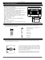
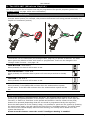
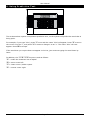
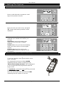
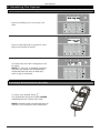
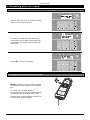
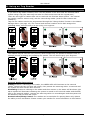
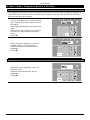
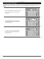
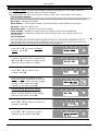
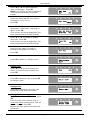
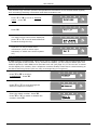
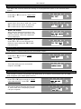
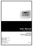
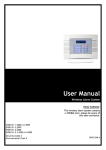
EN50131-1:2006+A1:2009 EN50131-3:2009 EN50131-6:2008 EN50131-5-3:2005+A1:2008 PD6662:2010 Security Grade 2 Environmental Class II Software Version >9.13 User Manual Wireless Alarm System RINS1548-4 PIEZO WARNING The wireless system contains a loud siren, please be aware of this after an activation SMS CHARGES: If you’re using the SMS text messaging facility of the panel, you will be charged at 50p every two weeks for an SMS Server Update call. This charge is raised via use of a premium rate telephone number. Please see page 23 for details. Contents Page Contents Page ..................................................................................................................... 2 1. Introduction .................................................................................................................... 4 2. The Setting Devices .......................................................................................................... 5 2.1 The Wireless Panel Keypad and Additional Keypads (EUR-068) ........................................... 5 2.2 The Internal Tag Reader (EUR-107) ................................................................................ 5 2.3 The External Tag Reader (EUR-108) ............................................................................... 5 3. The KF4-WE (Wireless Keyfob) ........................................................................................... 6 3.1 Locking the Keyfob ...................................................................................................... 6 3.2 Buttons ...................................................................................................................... 6 3.3 Quick Setting .............................................................................................................. 6 4. Using Predictive Text ........................................................................................................ 7 5. Setting The System .......................................................................................................... 8 5.1 Using a PIN Code or Tag ............................................................................................... 8 5.2 Using the Wireless KEyfob (KF4-WE) .............................................................................. 8 6. Unsetting The System .......................................................................................................9 6.1 Using a PIN Code or Tag ............................................................................................... 9 6.2 Using a Wireless Keyfob (KF4-WE) ................................................................................. 9 7. Unsetting after an alarm.................................................................................................. 10 7.1 Using a PIN Code or Tag ............................................................................................. 10 7.2 Using a Wireless Keyfob (KF4-WE) ............................................................................... 10 8. Using an Tag Reader ....................................................................................................... 11 8.1 Setting and Unsetting ................................................................................................. 11 8.2 Entry Control............................................................................................................. 11 9. Anti Code / Engineer Restore Facility ................................................................................. 12 9.1 Anti-Code ................................................................................................................. 12 9.2 Engineer Reset .......................................................................................................... 12 10. Intelligent Setting ......................................................................................................... 13 11. Fault Indications / Unable To Set .................................................................................... 14 11.1 Fault Indications ...................................................................................................... 14 11.2 Unable to Set .......................................................................................................... 14 11.3 Keyfob Fault Indications ............................................................................................ 14 12. Advanced Functions ...................................................................................................... 15 12.1 Chime Feature ......................................................................................................... 15 12.2 Omitting Inputs ....................................................................................................... 15 12.3 Keypad Hold Up ....................................................................................................... 15 13. Master Manager Menu ................................................................................................... 16 13.1 Entering the Master Manager Menu ............................................................................. 16 13.2 Exiting the Master Manager Menu ............................................................................... 16 13.3 Set Date and Time ................................................................................................... 17 13.4 Omit Inputs............................................................................................................. 17 13.5 Change Codes (Adding codes, tags and keyfobs) .......................................................... 18 13.5.1 Button Actions: .................................................................................................. 18 13.5.2 Flexi Set ............................................................................................................ 18 13.6 Review Logs ............................................................................................................ 20 13.7 Phonebook .............................................................................................................. 20 13.8 Walk Test ............................................................................................................... 21 13.9 Siren Test ............................................................................................................... 21 13.10 Start CHC SMS Update ............................................................................................ 21 13.11 Dial Out Menu ........................................................................................................ 22 13.12 Allow Engineer Menu ............................................................................................... 22 13.13 Block Remote Set ................................................................................................... 22 13.14 Block UDL ............................................................................................................. 23 14. Disclaimer ................................................................................................................... 23 15. Engineer Contacts and Tables ......................................................................................... 24 15.1 Engineer Information ................................................................................................ 24 15.1.1 Intruder Alarm Signal .......................................................................................... 24 15.1.2 Tamper Alarm Signal........................................................................................... 24 15.1.3 Keypad ............................................................................................................. 24 15.1.4 Tag Reader (Or Tag at a keypad) .......................................................................... 24 15.2 Certification ............................................................................................................ 24 15.3 Input Contact Table .................................................................................................. 25 15.4 Code Table .............................................................................................................. 26 Default User Code: 1234 Default Master Manager: 2222 User Manual 1. Introduction Two Way Wireless Security Protects Your Family and Property Without Compromise. This wireless alarm system has been designed with your security in mind; with quick and easy installation and minimal maintenance, this system protects your home or property with a multitude of unique features. Taking full advantage of the innovative two way wireless technology, the wireless devices on this system are constantly communicating with each other, using High Security Wireless Encryption Protocol. Compared to a conventional one way wireless system, where devices can be ‘asleep’ for up to five minutes at a time, therefore compromising your security, this wireless alarm system ensures your safety at your home or office at any time. This wireless alarm system has been engineered to be secure, reliable and easy to use. It includes the following features: Battery Monitoring/Saving Advanced technology preserves the battery life of each wireless device. However, the system informs you when a battery needs replacing a month in advance before the device stops working. This key feature gives you enough time to change the battery in the specific device. Conventional wireless alarm systems may not give you a low battery warning signal, meaning that devices could stop working, leaving your environment unprotected. Intelligent Setting This feature enables the control unit to automatically recognise when you’re at home or away. Using this knowledge this system is able to set itself in the correct mode without you having to choose. User Friendly Keyfobs The fully two way wireless keyfob allows you to see the status of the control unit via 3 colour LEDs: System set: When the system is set a RED LED will illuminate System unset: When the system is unset a GREEN LED will illuminate System fault: When the system is in fault condition an AMBER LED will illuminate. It is possible to allocate different functions to each keyfob such as setting / unsetting different areas, activating outputs, requesting system status, and activating panic alarms. Up to 32 wireless keyfobs can be added to the wireless alarm system. Each wireless keyfob has its own user ID which can be reported to the ARC and stored into the event log of the control panel individually. The keyfob also allows you to set/unset every area individually, giving you total control of your system. User Automation Outputs User automation outputs gives you the option to operate up to 20 devices such as gates, lights, sprinklers, etc. via your keypad or remotely via your keyfob, extending the use of your security system SMS Text Notifications Receive notifications via SMS text messages of any incidents within your home in real time. This can be programmed to send a notification in different situations: System is set or unset: Notification that your child has returned home from school safely. Alarm activation: Notification that the alarm has been triggered, allowing you to monitor your home from anywhere in the world. This wireless alarm system has 4 area's in which may be set up in the following way: Area A: Full set of the house Area B: Downstairs unset. Upstairs set. Area C: Garage set. Rest of house unset. Your engineer will be able to design the system according to your needs. Page: 4 User Manual 2. The Setting Devices 2.1 The Wireless Panel Keypad and Additional Keypads (EUR-068) Additional wired keypads may also be connected to the wireless control panel, please ask your Engineer for more information. a = Exits the Master Manager menu (page: 16), and selects Area A when setting. b = Moves backwards in the Master Manager menu (page: 16), and selects Area B when setting. c = Enables chime, displays additional information in the event log, and selects Area C when setting. D = Moves forward in the log, scrolls between options and enters the Master Manager menu (page: 16), and selects Area D when setting. f p = Not used. [ ] = Directional buttons and enables/disables functions. I = Selects commands A = Cancels items, resets the panel and moves to next item in a menu item. 2.2 The Internal Tag Reader (EUR-107) The Internal tag reader can be used for setting/unsetting, entry control or access control. Ask your engineer for more details. Tag Area (Where you present your tag to set/unset) Alert LED Alarm LED Tamper LED Fault LED Unset LED 2.3 The External Tag Reader (EUR-108) The External tag reader can be used for setting/unsetting, entry control or access control. Ask your engineer for more details. To set/unset the system using the External Tag Reader, present a pre-programmed tag to the centre of the prox. The prox will display the system status: Green = Unset. Red = Set. Present the tag again within 10 seconds and the system will set or unset. The system will then set depending on the type of exit mode programmed (Final door, Timed or Push to set) Page: 5 User Manual 3. The KF4-WE (Wireless Keyfob) The wireless keyfob has 4 buttons that may be programmed for specific purposes (please see ‘CHANGE CODES’ on page 18 for more information). 3.1 Locking the Keyfob All 4 buttons on the keyfob may be ‘locked’ so that any accidental presses will not affect your wireless alarm system (for example, this protects the buttons from being pressed accidently if a keyfob is in someone’s pocket). 3.2 Buttons The buttons can be customised (see Change Codes, page 18) to operate as desired. The table below gives the defaults of how each button is programmed. These can be changed in the ‘Change Codes’ function – see page: 18. LOCK BUTTON = Set Area A When pressed, the Area A will be start to set. UNLOCK BUTTON = Unset Area. When pressed, the wireless alarm system will unset any area that is already set. I BUTTON = Set Area B When pressed, the Area B will be start to set. II BUTTON = Show Status When pressed, if the GREEN LED is shown then the wireless alarm system will be unset. If the RED LED is shown then the wireless alarm system will be set. 3.3 Quick Setting If one of the buttons is programmed as ‘Set Area’, the wireless alarm system can be set by pressing the programmed button on the keyfob. The keypad will then start to count down the exit time, or wait for a ‘final door’ to be opened and closed or wait for a Push to Set (PTS) button to be pressed (depending what the exit mode is programmed as by the engineer). Once the alarm panel is in this ‘setting’ stage, it is possible to ‘quick set’ the system by pressing the same button again; this will reduce the time to set to ‘immediate setting’. The alarm panel will revert to the normal display with the time showing, but a beep will be heard once the system has been set. Please note this feature cannot be used if ‘Intelligent Setting’ is enabled. Page: 6 User Manual 4. Using Predictive Text The wireless alarm system incorporates predictive text, so the system will predict the word that is being spelt. For example, if you type ‘John’, press 5 once and the name ‘Julia’ will appear. Press D to move the cursor over the ‘u’, and press 6 3 times to change it to an ‘o’. The name ‘John’ will now appear. Press I to accept. If the word that you require does not appear in the list, just continue typing the word letter by letter. In addition, the a b c D keys are used as follows: a = make the character into a capital b= move cursor left c= clears cursor / adds a space D = moves cursor right Page: 7 User Manual 5. Setting The System 5.1 Using a PIN Code or Tag Enter a valid PIN code or present a valid tag to the symbol as shown. Enter the area you wish to set, and press I. ‘Please wait setting wireless’ will be displayed. There are three different setting methods your installer will instruct you through: Final Door: Leave the building and make sure the exit door is closed properly. Timed: Make sure you leave the building before the timer shown on the keypad expires. Push to set: Press the push to set button installed by your engineer to set the system. 5.2 Using the Wireless KEyfob (KF4-WE) To set via a keyfob. Pressand hold for more than 2 seconds. The keyfob LED will start to flash GREEN indicating that the system is starting to set. ‘Please wait setting wireless’ will be displayed on the keypad and the programmed area will begin to set. To ‘quick set’, press and hold thekey a second time for 4 seconds. Once set, the keyfob LED will illuminate RED indicating that the system is now set. Page: 8 User Manual 6. Unsetting The System 6.1 Using a PIN Code or Tag Enter the building, the 'entry time' will start. Enter a valid PIN code or present a valid tag to the symbol as shown. The area that the code is assigned to will be unset. NOTE: If ‘flexi-set’ is disabled (see page 18) then the system will automatically Unset that level set once a valid user code or tag is presented. 6.2 Using a Wireless Keyfob (KF4-WE) To unset via a keyfob. Press . The keyfob LED will start to flash GREEN indicating that the system has unset. NOTE: Unsetting with a keyfob will only be allowed if your engineer has enabled this. Page: 9 User Manual 7. Unsetting after an alarm 7.1 Using a PIN Code or Tag Enter a valid PIN code or present a valid tag to the symbol as shown. The alarm symbol will flash indicating there has been an alarm activation and the keypad will display which input has activated. Press A to reset the system. 7.2 Using a Wireless Keyfob (KF4-WE) NOTE: Unsetting with a keyfob will only be allowed if your engineer has enabled this. To unset via a keyfob. Press . The keyfob LED will start to flash GREEN indicating that the system has unset. Resetting the system after an alarm can only be done at the keypad. Page: 10 User Manual 8. Using an Tag Reader 8.1 Setting and Unsetting If you have a tag reader installed, then it will be possible to set and unset the wireless alarm system using a tag (the same tags can also be used to set/unset via the keypad prox). There are two types of readers that can be used with the wireless alarm system - the internal tag reader (used for indoors only) and the external tag reader (used for both indoors and outdoors). Tags for the readers need to be programmed through the ‘Change Codes’ function in the Master Manager Menu (see page 18). The internal and external readers can be both assigned to individual areas, this will need to be set up by your engineer. 8.2 Entry Control The readers may be used for entry control, which means they can operate automatic locks for example as well as setting and unsetting the system. This can be set up by your Engineer. External Reader Instructions: Arming: Present a valid tag to the reader, the GREEN LED will illuminate on the external reader, remove the tag, the door will unlock, then present the same tag within 10 seconds and the system will arm and the door will lock. Disarming: Present a valid tag to the reader and then remove it, the status will be shown (the alarm symbol will illuminate indicating the system is armed on the internal reader and the RED LED on the external reader), present the same tag within 10 seconds again and the system will be disarmed, and the door will unlock. Access Control/Entry Control: The readers can be used also for opening doors only without the ability to arm and disarm. Please contact your installer for more information on this feature. Page: 11 User Manual 9. Anti Code / Engineer Restore Facility 9.1 Anti-Code Your Engineer may have set up the system so that either an ‘Anti-Code’ or 'Engineer Restore' is required in order to fully reset the wireless alarm system (your code will still silence the alarm, but it will not reset the system). After alarm activation has occurred, enter a valid PIN code, or preset a valid tag, or press on the keyfob to silence the alarm. The keypad will display as shown to the right. Take note of the number, on the screen and call your Alarm Receiving Centre (ARC). Press I. When the time is displayed, enter the number given to you by the ARC. ‘Engineer Restore Performed’ will be displayed. Press A . 9.2 Engineer Reset When the time is displayed, enter the Engineer code. ‘Engineer Reset Performed’ will be displayed. Press A. Page: 12 User Manual 10. Intelligent Setting If intelligent set is enabled by your engineer, the system automatically recognises whether to full set (Area A), or part set. (Area B). ‘Flexi Set’ (Page 18) should be disabled for this feature to work properly. Enter a valid PIN code, or present a valid tag to the circled area, or press on the keyfob. The system will set in area B (the user code/tag/keyfob must be programmed for areas A and B). If a final exit input is activated during the setting procedure the system will quick set area A. Page: 13 User Manual 11. Fault Indications / Unable To Set 11.1 Fault Indications Any faults that occur on the system will be easily recognised by the flashing ALERT LED. To see what the fault is, enter a valid PIN code, or present a valid tag, or press on the keyfob. Depending on how the system has been set up by your engineer, it may be possible to set the system with a fault, to do this press I. Any fault may affect the overall performance of your alarm control panel and therefore your engineer should be contacted for further assistance if any fault is active. 11.2 Unable to Set If ‘unable to set’ is displayed, it indicates that an input is open and the area where the input is should be checked for open windows, pets, movement etc. If the problem cannot be solved contact your Engineer, or omit the input (page 15) 11.3 Keyfob Fault Indications If the panel is unable to set for any reason, the keyfob status LED flashes AMBER indicating a fault is on the system. The fault will be shown on the keypad. Page: 14 User Manual 12. Advanced Functions 12.1 Chime Feature The chime can be used for any input on the system. This can be set up by your engineer. To enable the chime on the keypad, when the time is displayed, press c . ‘c’ will be displayed on the right side of the keypad display. Press c again to clear the chime feature. 12.2 Omitting Inputs On occasion, a detector may need to be isolated if a room is occupied. Enter your user code Press I . Select the inputs that need to be omitted Press A. After 10 seconds the exit time continues. NOTE: Inputs have to be programmed as ‘omittable’ by your Engineer for this feature to operate. 12.3 Keypad Hold Up If an emergency alarm is needed, press and hold both 1 and 7 . A ‘hold up’ alarm will be generated. NOTE 1: The Hold Up facility needs to be enabled by your engineer (either silent or full alarm) 2-Key HU and any duress codes programmed on the system by your engineer are not permitted to send a signal to the Alarm Receiving Centre under police regulations in England, Wales or Northern Ireland NOTE 2: The keyfob can also be programmed to support a hold up alarm. Please discuss this with your Engineer. Page: 15 User Manual 13. Master Manager Menu The Master Manager Menu has the following functions: Function Set Date and Time Omit Inputs Change Codes Review Logs Phone Book Walk Test Siren Test Start CHC SMS Update Dial Out Menu Allow Engineer Menu Block Remote Set Block UDL Exit Manager Mode Description Programs the date and time. Omits any 24 inputs only (except Personal Attack inputs). Adds/Edits/Deletes User PIN codes, tags and keyfobs. Displays all event log information. Adds/Edits/Deletes SMS phone numbers if enabled. Tests each input. Tests each external sounder. Sends a test call to the SMS station if SMS is being used. Used for uploading/downloading. Enables or Disables Engineer access. Blocks remote setting from the PC software. Blocks uploading/downloading from the PC software.. Exits the Master Manager menu. NOTE: The Master Manager code allows access to all the options above. A ‘user code’ has access to the ‘User Menu’ which includes the functions: ‘CHANGE CODE', ‘REVIEW LOGS’, ‘ALLOW ENGINEER MENU', and ‘EXIT USER MENU’. 13.1 Entering the Master Manager Menu Press D. Enter the Master Manager code or present the Master Manager tag. Press b or A to scroll through the different functions mentioned above. 13.2 Exiting the Master Manager Menu Press b or A keys to scroll through until ‘EXIT MANAGER MODE' is displayed. Press I. Or, when a main menu item is displayed (capital letters) press the a key. Page: 16 User Manual 13.3 Set Date and Time Press b or A to scroll to ‘SET DATE & TIME’. Press I. Enter the Year. Press I. Enter the Month. Press I. Enter the Day. Press I. Enter the Hours. Press I. Enter the Minutes. Press I. 13.4 Omit Inputs Press b or A to scroll to ‘OMIT INPUTS’. Press I. Enter the inputs you require to be omitted for the next setting procedure. Press I. NOTE: All inputs will be only omitted for the next setting procedure. Page: 17 User Manual 13.5 Change Codes (Adding codes, tags and keyfobs) The ‘CHANGE CODES’ function allows adding, editing and deleting of user codes, tags and keyfobs. The master manager code can also be changed. The control panel can have up to 80 user codes or tags. Up to 32 keyfobs can be learnt. 13.5.1 Button Actions: Each wireless keyfob has 4 buttons that can be programmed for any of the functions below: No Action = Disables the button Show Status = If the keyfob is learnt the LED will flicker when asked for the status. Set Area = Sets the chosen area Unset Any Area = Unsets any area on the system Latch Output = Enables an output that your engineer may have programmed Timed Output = Enables an output for a period of time that your engineer may have programmed 13.5.2 Flexi Set Flexi-set allows you to choose which level/area to set if a user code is assigned to one or more levels/areas. If this function is disabled, when a user code is entered, the system will automatically set the levels/areas that the code is assigned to. Press b or A to scroll to ‘CHANGE CODES’. Press I. To add a new code, tag, or keyfob press I. Press A to delete or change a user code (see further down for details). Press [ or ] to choose a user number. Press I. Enter the new code, present a tag or press and hold a keyfob button until the display changes. Once ‘asterisks’ appear, the tag or user code will be now assigned to this user. Press I. Programming Wireless Keyfobs If a keyfob is programmed, the 'User Name' will be displayed on the keypad. Enter the user name. Press I. Press [ or ] to choose the button to program. Press I. Press [ or ] to choose the action assigned to the button. Press I. Page: 18 User Manual Press [ or ] to choose between 'User' or 'Manager'. Press I NOTE: This screen will not be displayed if you have programmed a wireless keyfob. Select the areas that the user will be assigned to: A, B, C or D. Press I. Press [ or ] to choose between 'Unset/Set', 'Unset Only', 'Set Only' or 'None'. Press I. (This screen will not be displayed if you have programmed a wireless keyfob) Press [ or ] to enable or disable 'Flexi-Set'. Press I. (This screen will not be displayed if you have programmed a wireless keyfob) Enter the user name (for help on predictive text please see page 7) Press I. Press I to delete or change a user. Delete User Press [ or ] to scroll through the users, or enter the user number and press I. Press I to delete a user, or press A to change a user. Change User Press I to change a user code, and follow the screen shots previously. Change Master Manager Code To edit the Master Manager Code, press I. Enter the new code, present a tag or press and hold a keyfob button until the display changes. Press I. Repeat the same procedure mentioned previously. Page: 19 User Manual 13.6 Review Logs The ‘Review Logs’ function monitors all operational information of the wireless alarm system, such as setting/unsetting information and alarm activations etc. Press b or A to scroll to ‘REVIEW LOGS’. Press I. Press I. The most recent event will be displayed, press b or D to scroll backwards and forwards through the log. Press the c key to show more information (such as which input activated, or which user set the system etc) 13.7 Phonebook If SMS texting is programmed, there will be up to 4 mobile numbers also programmed which can be changed in this function. If any numbers are added, you will need to enable each one and also perform a CHC SMS test to activate each call (see page 21). If “do not use” is shown on the display of a number, then a telephone number already exists that is communicating to an Alarm Receiving Centre (this can only be changed by your engineer). Press b or A to scroll to ‘PHONEBOOK’. Press I. Press b or D to scroll through the different telephone numbers. Enter the mobile number. Press I. Press [ or ] to enable or disable the number. Press I. Page: 20 User Manual 13.8 Walk Test The ‘Walk Test’ function allows the testing of all programmed inputs on the wireless alarm system. Press b or A to scroll to ‘WALK TEST’. Press I. Select which level set to walk test. Press I to walk test all inputs or press the A to walk test an input individually. Walk Test Inputs Walk test the mentioned inputs on the display. After all inputs have been walk test successfully ‘walk test completed’ will be displayed. Walk Test Individual Inputs Press [ or ] to scroll through the different inputs and press I to walk test that input. 13.9 Siren Test This function is used to test the siren and strobe outputs. Press b or A to scroll to ‘SIREN TEST’. Press I. This tests both the siren and strobe outputs. Press I. 13.10 Start CHC SMS Update This function is used in conjunction with SMS texts. It is used to communicate with the SMS Host computer (the mobile phone server). Press b or A keys to scroll to ‘START CHC SMS UPDATE'. Press I. The control panel will then call the CHC. If ‘Failed CHC test’ is displayed, please call your engineer. Page: 21 User Manual 13.11 Dial Out Menu The control panel may be dialled into, and programming information kept on a PC using the InSite UDL software. This function allows the control panel to dial a Pre-programmed PC telephone number (programmed by your engineer) to directly dial to a PC. This is usually used when your engineer requests it. Press b or A keys to scroll to ‘DIAL OUT MENU’. Press I. Press [ or ] to scroll through the different PC numbers, press I to dial that number Press [ or ] to select the operation that needs to be performed. Press I. The control panel will dial the programmed PC. If this fails please contact your engineer. Press A. 13.12 Allow Engineer Menu If this function is enabled, the engineer will require authorisation from you before they can access the engineering menu. Press the b or A keys to scroll to ‘ALLOW ENGINEER MENU’. Press I. Press [ or ] to select either ‘Yes’ or ‘No’. Press I. 13.13 Block Remote Set Your wireless alarm system may be configured so that your alarm installation company can remotely set/unset. Should you wish to block this access, you can enable this function Press the b or A keys to scroll to ‘BLOCK REMOTE SET’. Press I. Press [ or ] to select either ‘Yes’ or ‘No’. Press I. Page: 22 User Manual 13.14 Block UDL Your wireless alarm system may be configured so that your alarm installation company can upload and download into the control panel, Should you wish to block this access, you can enable this function. Use the b and A keys to scroll to ‘BLOCK UDL’. Press the I key Press [ or ] to select either ‘Yes’ or ‘No’. Press I. 14. Disclaimer GSM Communications The wireless alarm system GSM has the ability to send: 1. Electronic messages to an Alarm Receiving Centre (ARC) 2. Short Message Services (SMS). In order for the wireless alarm system GSM to function correctly, the installer must provide and fit a SIM card that has an appropriate airtime contract with a suitable Wireless Network Operator (WNO). Electronic messages and SMS messages are carried by the WNO by means of networks and transmission facilities over which Pyronix Limited (Pyronix) has no control. Pyronix shall therefore not be responsible for the WNO’s service level or the WNO’s network failures. PSTN Communications The wireless alarm system PSTN Modem has the ability to send: 1. Electronic messages to an Alarm Receiving Centre (ARC), 2. Text Messages via Short Message Services (SMS). In order for the wireless alarm system PSTN Modem to function correctly, the installer must connect the wireless alarm system PSTN Modem to an appropriate Plain Old Telephone System (POTS) which has an appropriate service level agreement with a suitable POTS operator. Moreover, the service level agreement must allow the wireless alarm system PSTN the ability to dial Premium Rate numbers. In order for the wireless alarm system PSTN Modem to send SMS messages, the wireless alarm system PSTN Modem must dial an embedded number that connects to an SMS server. The wireless alarm system PSTN Modem passes the SMS message to the SMS server, which in turn forwards the SMS to the user’s mobile phone. Please check with your installer for exact charges. The PSTN Modem will contact our own Host Computer periodically in order to check and verify the SMS server routing information. Charges for this service are raised by use of a premium rate telephone number and are currently 50p per call*. Electronic messages and SMS messages are carried by the POTS/SMS Server operator by means of networks and transmission facilities over which Pyronix Limited (Pyronix) has no control. Pyronix shall therefore not be responsible for the POTS/SMS Server operator’s service level or the POTS/SMS Server operator’s network failures. *Charges correct as of 31/3/2014 Page: 23 User Manual 15. Engineer Contacts and Tables 15.1 Engineer Information Alarm Company Date of Installation Site Reference Engineer Name Engineer Contact Number Installed to Grade Environmental Class II Your panel is suitable for use in installations designed to meet the European requirements of Security Grade 2, Environmental Class 2. When all parts are working normally, this equipment in combination with the PSTN or GSM and suitable ARC equipment will meet the requirements of ATS2. External set/unset readers and wireless sirens meet the requirements of environmental class 4. Number of Code Differs: tag hex code. Your panel is designed to automatically inhibit certain functionality. The factory default settings are shown below: 15.1.1 Intruder Alarm Signal After 3* unconfirmed alarms in the same area or 1 confirmed alarm. * This figure is programmable by the Engineer. 15.1.2 Tamper Alarm Signal After 3* unconfirmed alarms in the same area or 1 confirmed alarm. * This figure is programmable by the Engineer. 15.1.3 Keypad After 30 key presses without entering a valid code, keys are disabled for 90 seconds. After reinstatement, this will be repeated after each 7 key presses until a valid code is entered. 15.1.4 Tag Reader (Or Tag at a keypad) After 6 presentations of an invalid tag, the reader will be disabled for 90 seconds. After reinstatement, this will be repeated for each invalid tag until a valid tag is used. 15.2 Certification All Wireless devices comply with the following EU requirements: EMC Directive Low Voltage Directive R&TTE Directive And meet the following EN 61000-6-3:2007 +A1:2011 EN 50130-4:2011 2004/108/EC 2006/95/EC 1999/5/EC standards where relevant: EMC. Generic emission standard. Residential, commercial and light industry Immunity requirements for components of fire, intruder and social EN 60950-1:2006 +A12:2012 Information technology equipment. Safety. General requirements EN 50131-5-3:2005+ A1:2008 Grade 2. Interconnections for equipment using radio frequency techniques ETSI EN 3014893:2000 ETSI EN 300 220 CEPT/ERC EMC. Radio equipment. Part 3: Short range devices (SRD) 9kHz to 40GHz EMC. Receiver Class 1, Environmental Category 1 Recommendation 70-03 Annex 1 Compliant operation is only guaranteed when installed and operated according to the relevant installation and user manuals. Page: 24 User Manual 15.3 Input Contact Table Input No Input Name Input Areas 1 2 3 4 5 6 7 8 9 10 11 12 13 14 15 16 17 18 19 20 21 22 23 24 25 26 27 28 29 30 31 32 33 34 35 36 37 38 39 40 41 42 43 44 45 46 47 48 49 50 51 52 53 54 55 56 Page: 25 Description User Manual Input No Input Name Input Areas Description 57 58 59 60 61 62 63 64 65 66 15.4 Code Table Code No Code Type (Code/Tag/Fob) Code Areas 1 2 3 4 5 6 7 8 9 10 11 12 13 14 15 16 17 18 19 20 21 22 23 24 25 26 27 28 29 30 31 32 33 34 35 36 37 38 39 40 41 42 43 Page: 26 Code Name User Manual Code No Code Type (Code/Tag/Fob) Code Areas 44 45 46 47 48 49 50 51 52 53 54 55 56 57 58 59 60 61 62 63 64 65 66 67 68 69 70 71 72 73 74 75 76 77 78 79 80 Page: 27 Code Name For electrical products sold within the European Community: At the end of the electrical product’s useful life, it should not be disposed of with household waste. Please recycle where facilities exist. Check with your Local Authority or retailer for recycling advice in your country. When disposing of the product the batteries must be removed and disposed of separately in accordance with the local regulations