1
Telegesis ZigBee RangeFinder
Telegesis
TG-RF-PM-501 ZigBee RangeFinder
ZigBee RangeFinder
Product Manual 0501 r8
Telegesis ZigBee RangeFinder
Product Manual
Rev: 8
Date: Sept 2014
Guide for firmware versions: R311 and R211
Patent pending: GB1222898.7
©2012 Telegesis (UK) Ltd
-1-
Telegesis ZigBee RangeFinder
Telegesis ZigBee RangeFinder
Table of Contents
Table of Contents.............................................................................................................................. 2
Package Contents............................................................................................................................. 5
Specifications .................................................................................................................................... 6
Handheld Terminal (HHT).............................................................................................................. 6
Satellite (SAT-x) ............................................................................................................................ 6
Handheld Terminal Unit .................................................................................................................... 7
Layout ........................................................................................................................................... 7
Functionality .................................................................................................................................. 9
Start-up: ................................................................................................................................... 10
Menu Screens: ......................................................................................................................... 11
Normal Test Modes: ................................................................................................................. 12
Continuous Test Modes: .......................................................................................................... 16
Device Configurations: ............................................................................................................. 22
Firmware Upgrades: ................................................................................................................ 26
Data Logging: .......................................................................................................................... 29
Device Info ............................................................................................................................... 32
Adjust Contrast ........................................................................................................................ 32
Power .......................................................................................................................................... 34
Batteries .................................................................................................................................. 35
Charging .................................................................................................................................. 35
Power Saving ........................................................................................................................... 35
Satellite Unit .................................................................................................................................... 36
Layout ......................................................................................................................................... 36
Functionality ................................................................................................................................ 37
Buttons .................................................................................................................................... 37
LEDs ........................................................................................................................................ 37
Power .......................................................................................................................................... 38
Batteries .................................................................................................................................. 38
Power Consumption ................................................................................................................. 38
Usage ............................................................................................................................................. 38
System Topology ......................................................................................................................... 38
Workflow ..................................................................................................................................... 40
©2012 Telegesis (UK) Ltd
-2-
Telegesis ZigBee RangeFinder
Telegesis ZigBee RangeFinder
Interpreting Test Results ................................................................................................................. 41
RSSI Calculation ...................................................................................................................... 41
Packet Error Rate .................................................................................................................... 41
Pass/Fail Criteria...................................................................................................................... 41
Warranty ......................................................................................................................................... 42
Compliance with Laws and Regulations .......................................................................................... 44
Disclaimer ....................................................................................................................................... 44
Contact Information ......................................................................................................................... 44
©2012 Telegesis (UK) Ltd
-3-
Telegesis ZigBee RangeFinder
Telegesis ZigBee RangeFinder
Table of Figures
Figure 1: Package Contents .............................................................................................................. 5
Figure 2: Handheld Terminal Front.................................................................................................... 7
Figure 3: Handheld Terminal Back .................................................................................................... 8
Figure 4: Product Label ..................................................................................................................... 9
Figure 5: Start-up Screen ................................................................................................................ 10
Figure 6: Start-up Screen ................................................................................................................ 11
Figure 7: Pre-Test Screen ............................................................................................................... 12
Figure 8: Test Start Screen ............................................................................................................. 13
Figure 9: Screen for Test A and B ................................................................................................... 14
Figure 10: Energy Scan Screen ...................................................................................................... 15
Figure 11: Tx tone ........................................................................................................................... 16
Figure 12: Continuous Ping Configuration ....................................................................................... 17
Figure 13: Continuous Ping Results ................................................................................................ 18
Figure 14: Single Channel E-Scan .................................................................................................. 19
Figure 15 One hop configuration screen ......................................................................................... 20
Figure 16 One Hop Test Result Screens ......................................................................................... 20
Figure 17: Configurations Screen .................................................................................................... 23
Figure 18: Advanced Configurations Screen ................................................................................... 24
Figure 19: Configurations Parameter Limits .................................................................................... 25
Figure 20 Firmware Upgrade Screens ............................................................................................ 26
Figure 21 HHT Firmware Upgrade .................................................................................................. 26
Figure 22 HHT Firmware upgrade options ...................................................................................... 27
Figure 23 SAT Firmware Options .................................................................................................... 28
Figure 24 Data Logger Screen ....................................................................................................... 29
Figure 25: Device Information Screen ............................................................................................. 32
Figure 26: Adjust Contrast Screen .................................................................................................. 32
Figure 27: Battery Symbol ............................................................................................................... 35
Figure 28: Battery Charging Symbol ............................................................................................... 35
Figure 29: Satellite Front ................................................................................................................. 36
Figure 30: Satellite Back ................................................................................................................. 36
Figure 31: Satellite Product Label ................................................................................................... 37
Figure 32: Satellite LED States ....................................................................................................... 37
Figure 33: A typical floor plan with Smart Energy equipment locations ............................................ 38
Figure 34: RangeFinder locations: Electric meter, Gas meter and Kitchen work surface ................. 39
Figure 35: Workflow ........................................................................................................................ 40
©2012 Telegesis (UK) Ltd
-4-
Telegesis ZigBee RangeFinder
Telegesis ZigBee RangeFinder
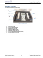
Package Contents
The package contains the following items,
(a)
(b)
(g)
(c)
(d)
(f)
(e)
Figure 1: Package Contents
a)
b)
c)
d)
e)
f)
g)
1x Quick Start Guide
4x 1.5V AA Alkaline Batteries
2x Satellite Units SAT100
1x USB A to USB Micro Cable
1x Handheld Terminal ZHT100
2x 1.2V AA 2000mA Rechargeable Batteries
3x 2.4GHz Half-wave Antennas
©2012 Telegesis (UK) Ltd
-5-
Telegesis ZigBee RangeFinder
Telegesis ZigBee RangeFinder
Specifications
Handheld Terminal (HHT)
Model Number
RF Interface
RF Output Power
Antenna
Battery
Charging
Operating Temperature
Humidity
IP Rating
ZHT100
2.4GHz IEEE802.15.4
-9dBm to +8dBm (Standard Version)
20,19,18,16,15,13,10,7,1dBm (Long Range Version)
Half-wave Dipole Antenna 2dBi Gain
2x 1.2V 2000mAH NiMH Rechargeable
5Volts @ 300mA via USB Micro Connector
0 to 50C
95% TH Non-condensing
IP54 (subject to testing)
Satellite (SAT-x)
Model Number
RF Interface
RF Output Power
Antenna
Battery
Operating Temperature
Humidity
IP Rating
©2012 Telegesis (UK) Ltd
SAT100
2.4GHz IEEE802.15.4
-9dBm to +8dBm (Standard Version)
20,19,18,16,15,13,10,7,1dBm (Long Range Version)
Half-wave Dipole Antenna 2dBi Gain
2x 1.5V AA Alkaline Batteries
0 to 50C
95% TH Non-condensing
IP54 (subject to testing)
-6-
Telegesis ZigBee RangeFinder
Telegesis ZigBee RangeFinder
Handheld Terminal Unit
Layout
(a)
(b)
(f)
(c)
(d)
(e)
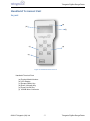
Figure 2: Handheld Terminal Front
Handheld Terminal Front
(a)
(b)
(c)
(d)
(e)
(f)
Product Model Number
LCD Display
Escape (Back) Key
Enter (Activate) Key
Power On/Off Key
USB-B Micro Connector
©2012 Telegesis (UK) Ltd
-7-
Telegesis ZigBee RangeFinder
Telegesis ZigBee RangeFinder
(a)
(b)
(c)
(e)
(f)
(d)
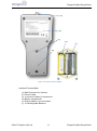
Figure 3: Handheld Terminal Back
Handheld Terminal Back
(a)
(b)
(c)
(d)
(e)
(f)
SMA Connector for Antenna
Product Label
2x Screw for Battery Compartment
Battery Compartment
Dummy Battery (non-removable)
2x Rechargeable Batteries
©2012 Telegesis (UK) Ltd
-8-
Telegesis ZigBee RangeFinder
Telegesis ZigBee RangeFinder
(a)
(i)
(b)
(c)
(d)
(h)
(e)
(f)
(g)
Patent pending: GB1222898.7
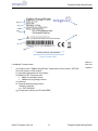
Figure 4: Product Label
Functionality
The Hand-Held Terminal (HHT) is the centre point of the system and all communication in
Handheld
Label to the HHT. The operator can set up parameters for tests, perform the
the
system Terminal
is with respect
tests and configure other test settings from the HHT. Below are the explanations of various options
(a) Product name “ZigBee RangeFinder” and product model number “ZHT100”
and output screens one can use on the HHT.
(b) Serial number of the product
(c) Operating parameters of the product
(d) Maximum RF Transmit power
8dBm for standard version
20dBm forLong Range version
(e) Warning
(f) Barcode with following content:
<Model>/L<Serial>
e.g. ‘ZHT100/L9001’
(g) Compliance marking for CE and WEEE
(h) Manufacturer’s logo
(i) Manufacturer’s contact information
©2012 Telegesis (UK) Ltd
-9-
Telegesis ZigBee RangeFinder
Telegesis ZigBee RangeFinder
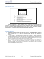
Start-up:
Upon pressing the power button
for four seconds the following screen will be
displayed. This screen has useful information about the product such as the serial numbers of
device and the firmware version of HHT. This screen is displayed upon power up and by Device Info
option on Menu screen 3.
a
c
d
(a)
(b)
(c)
(d)
(e)
(f)
RANGE FINDER
2.4GHz Zigbee
Network Surveyor
HHT : xxx
VER : xxx
IHD : xxx
GAS : xxx
Press Any Key
b
f
e
Product Name
Space for OEM Label
Serial Number of the HHT
Serial Number of SAT-A set to emulate IHD
Serial Number of SAT-B set to emulate GAS
Device Firmware version.
Figure 5: Start-up Screen
©2012 Telegesis (UK) Ltd
-10-
Telegesis ZigBee RangeFinder
Telegesis ZigBee RangeFinder
Menu Screens:
Menu items can be scrolled through using the navigations keys
and
to
navigate through options and press
button to enter the selected menu item. The battery
symbol shows the current battery status.
Menu Screen 1
a
PreTest
Test
A
Energy
Scan
Test
B
IG
Config
c
Menu Screen 2
a
Tx
Tone
b
Ch
Ping
FW
Upgrades
Ch
E-Scan
Data
Logger
Menu Screen 3
One Hop
Test
:
x
x
x
Device
Info
d
:
x
x
x
Adjust
Contrast
(a)
(b)
(c)
(d)
Menu Items
Single SAT / Dual SAT option
Battery status
Battery charging
:
x
x
x
Figure 6: Start-up Screen
©2012 Telegesis (UK) Ltd
-11-
Telegesis ZigBee RangeFinder
Telegesis ZigBee RangeFinder
Normal Test Modes:
Pre-Test:
A Pre-Test is required before the ‘Test A’ or ‘Test B’ can be performed. The Pre-Test has the
function of sanity checking the link between the HHT and the SAT units. Also performing Pre-Test
will configure the current test settings in SAT units. A test carried out without running a Pre-Test
may NOT present valid results. Any change in the Configuration settings should be followed by a
Pre-Test.
Pre-Test Screen
a
b
c
d
e
f
(a)
(b)
(c)
(d)
(e)
(f)
(g)
(h)
IHD
65534
GAS
65535
s
Link : OK
Link : NOK
IHD : 4%
IHD : 4%
RSSI :: -20
RSSI : -20
57%
Ch: 11
Pw:8dBm Bat:100%
g
h
Label of the first Satellite unit IHD
Serial number of Satellite Labelled IHD
Status of Pre-Test, OK for Success and NOK for Failure
indicated by Red backlight
Battery status of the IHD unit in percentage from 0 to 100%
RSSI of the received data during Pre-Test
HHT information
i. Channel used for Pre-Test
ii. Power output level for Pre-Test
iii. Battery status of HHT
Label of second Satellite unit GAS
Information as listed in (b) to (e) relating to second Satellite Unit
GAS
Figure 7: Pre-Test Screen
The completion of the Pre-Test is indicated by a short beep from the built-in buzzer. To return to the
main menu from the Pre-Test Screen please press
©2012 Telegesis (UK) Ltd
-12-
Telegesis ZigBee RangeFinder
Telegesis ZigBee RangeFinder
Test A / Test B:
Telegesis Range Finder tests are designed to evaluate the suitability of deployment of a
Smart Energy device which is why they focus on the ZigBee Smart Energy recommended RF
channels in the 2.4GHz spectrum. Tests A and B are performed on ZigBee SE channels 11, 14, 15
and 19 during Test-A, while the remaining of SE channels 20, 24 and 25 are tested in Test-B.
Although the Rangefinder is designed to assist with ZSE installations, the Continuous test
and Energy scan can be used to analyse the entire ZigBee 2.4GHz spectrum.
At the start of each test-A/B, countdown is activated to give a chance for the operator to
put the HHT in place of simulated test device such as electricity meter and move away from the
meter housing if necessary. This timer is configurable in the Configuration Menu.
To perform tests A or B, navigate to the menu item on Menu Screen 1 using
keys and press
and
button for the test start screen to appear. Continuous and
Test Start Screen
Test A
a
Tx:8dBm
c
02
b
Time to Start
(a)
(b)
(c)
Name of the test about to run (Test A in this case)
Countdown, the default value of the countdown is 5
seconds which can be changed through Config menu
Transmit power for the test
Figure 8: Test Start Screen
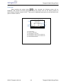
Once the countdown has elapsed, the test starts and the test results are displayed for each
channel for the test as the test progresses. The completion of the test is indicated by a short beep
from the built-in buzzer. The display backlight changes to Red for test failure and to Blue colour if
the test is a pass. Also the failed values will be inverted. For details of the Pass/Fail criteria please
see section “Interpreting Test Results”.
©2012 Telegesis (UK) Ltd
-13-
Telegesis ZigBee RangeFinder
Telegesis ZigBee RangeFinder
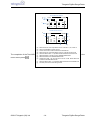
Test-A Results Screen
a
b
Test A
IHD
Ch
11
h
14
h
15
h
19
h
h
c
T
-54
-55
-58
-54
S
-55
-60
-63
-56
Tx:8dBm
GAS
T
S
-64
-64
-73
-76 x
-53
-56
-51
-51
Test-B Results Screen
d
Test B
IHD
e
Ch
20
h
24
h
25
h
T
S
-40
-75
-53
-40
-67
-56
Tx:8dBm
GAS
T
S
-40
-90
-55
-41
-86
-55
f
The completion of the Test-A/B is
menu screen press
©2012 Telegesis (UK) Ltd
j
i
h
x
g
(a) Name of the test, Test A represents test on channels 11,14,15 and 19
(b) Label of the Satellite unit such as IHD
(c) Column of channel numbers valid for the selected test
Figure 9: Screen for Test A and B
(d) Name of the test, Test B represents a test on channels 20,24 and 25
(e) Label for RSSI column. ‘T’ represents RSSI measured at the HHT end
indicated
by a short
beep
from
the built-in
To return
(f) RSSI measured
at the
HHT end
for Satellite
labelledbuzzer.
GAS
(g) RSSI measured at the Satellite labelled GAS
(h) Overall test result - tick for Pass and cross for a Fail. RSSI values will
inverted to indicated failed results
(i) Label for RSSI column. ‘S’ represents RSSI measured at the Satellite end
(j) Transmit power of the radio during the test
-14-
to the
Telegesis ZigBee RangeFinder
Telegesis ZigBee RangeFinder
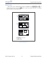
Energy Scan:
The operator can make use of the Energy Scan of the network to get a measure of the noise
or traffic present on a channel. Due to the dynamic nature of protocols (Wi-Fi, Bluetooth, ZigBee)
each scan may show a different noise level even when done back to back. Each channel is scanned
for noise for about 260mS. The results are painted for each channel as they become available.
-35dBm is considered to be very noisy and -85dBm is considered very quiet. The channels
preferred by the ZigBee Smart Energy standard are highlighted in the test results. A sample of the
test screen is shown below. To perform the Energy Scan, navigate to the Energy Scan menu item
on Menu Screen 1 using
and
shown below to appear on screen.
keys and press
for the energy scan result graph as
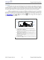
Energy Scan Results
a
b
0 1 2 3 4 5 6 7 8 9 AB C D E F
x
e
d
c
(a) A bar representing noise level on a channel, the value ranges from
-85dBm (bottom) to -35dBm (top)
(b) Channel number ‘0’ represents channel 11 of the ZigBee channels, it is
highlighted as it is one of the recommended channels according to the
ZigBee Smart Energy specification
(c) Channel number ‘F’ represents channel 26 of ZigBee channels, it is not
highlighted as it is not one of the channels recommended for use by
ZigBee Smart Energy specification
(d) A tick mark as legend indicates that shorter bars indicate low noise
level on a channel
(e) A cross
mark10:
as Energy
legend indicates
that the taller bars represent high
Figure
Scan Screen
noise level on a channel
©2012 Telegesis (UK) Ltd
-15-
Telegesis ZigBee RangeFinder
Telegesis ZigBee RangeFinder
Continuous Test Modes:
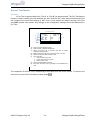
Tx Tone
The Transmit Tone option can be useful in situations in which one has to test immunity of the
existing ZigBee network against noise from other devices operating on the same channel. This
option will transmit a continuous tone on the user selected channel and power level. To transmit a
tone on a channel, navigate to the Tx Tone menu option on menu screen 2 using
and press
and
keys
for following screen to appear.
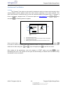
Tx Tone Test
a
b
c
d
TX : xxdBm
CH : xx
Tx Tone
Channel-xx
START
: xx
a.
b.
c.
d.
Editable values
The transmit power of HHT.
The channel number on which the continuous tone is transmitted.
START/PAUSE scan button.
Blinking symbol
indicate
that continuous transmission is ON.
Figureto11:
Tx tone
Once on this screen, the user can scroll through parameters using the
and
keys, press
to be able to edit the transmit power and channel number on which to transmit a continuous tone
which can be done using the
and
keys and again press
to set the new value.
After setting all the parameters, user will navigate to START option and press
to start
transmitting the tone. The symbol on the right will start blinking to indicate that the tone is being
transmitted on the set channel.
©2012 Telegesis (UK) Ltd
-16-
Telegesis ZigBee RangeFinder
a. The transmit power of HHT.
b. The channel number on which the continuous tone is transmitted.
Telegesis ZigBee RangeFinder
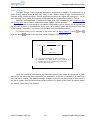
Ch Ping
This is another continuous mode tests which can be used whenever the user wants to find
the best location to position the IHD and GAS units to get the optimum signal strength that can be
achieved.
Single Channel Ping Config
i
a
TX
RTH
b
HHT
x
x
I/G
x
x
START
c
S-A
T
x
x
CH : xx
f
DUR
h
d
g
e
a.
b.
c.
d.
e.
f.
g.
h.
i.
HHT transmit power.
IHD transmit power.
GAS transmit power.
Channel for current test.
Duration of test.
Single/Dual SAT mode.
GAS RSSI threshold.
SAT RSSI threshold.
HHT RSSI threshold.
Figure 12: Continuous Ping Configuration
The main advantage of this test is the ability to set different test parameters such as Tx
Power and RSSI threshold limits in all three (IHD; GAS and HHT) devices. This gives the operator
flexibility to emulate different devices with different settings which can be the case in an actual
ZigBee network.
This option can be used to measure the RSSI between the HHT and the IHD and/or GAS
units. As with the other options navigate to the Ch Ping option on menu screen-2 using
and
keys and select the option using
key. The single channel Ping Config screen as shown above
will appear. There are different parameters as shown in the figure above which are to be set
according to test requirements. To scroll through list of parameters, use
Press
to edit,
and
to edit values and again press
continuous Ping test to be performed.
©2012 Telegesis (UK) Ltd
-17-
and
arrow keys.
to set the parameter value for the
Telegesis ZigBee RangeFinder
Telegesis ZigBee RangeFinder
Once all the parameter values are set press navigate to START and press
to start the
test. Now the test will run for the time in sec set for DUR parameter. If the time set is 0 then the test
will keep on running and updating the display with the Single Channel Ping Results screen unless
stopped manually by pressing
key.
Single Channel Ping Results
IHD
b
RSSI
a
PER
c
xx
xx
GAS
S
T
S
f
xx
xx
xx
g
xx
e
DUR : xx sec
CH : xx
d
a.
b.
c.
d.
e.
f.
g.
Received RSSI by HHT from IHD.
Received RSSI by IHD.
PER between HHT and IHD.
Channel on which test is being performed.
PER between HHT and GAS.
RSSI received by HHT from GAS.
RSSI received by GAS from HHT.
Figure 13: Continuous Ping Results
©2012 Telegesis (UK) Ltd
-18-
Telegesis ZigBee RangeFinder
Telegesis ZigBee RangeFinder
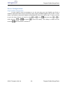
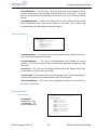
Ch E-Scan
This channel scan will show the dynamic values of the current noise levels in the selected
channel. To select this single channel E-Scan option, navigate to the option on menu screen 2
using
and
keys and press
. The following screen will appear.
Continuous E-Scan Test
x
-40
e
d
-85
-35
Ch : xx
a
a.
b.
c.
d.
e.
: xx
START
c
b
Editable values
The channel number on which the E-Scan is being
done.
START/PAUSE scan button.
Min RSSI threshold.
Max RSSI threshold.
Resultant Energy value on the Channel.
Figure 14: Single Channel E-Scan
Once on this screen, scroll through the list of channels (from CH-11 to CH-26) on which the noise
scan is to be done by using
and
keys and again press
to set the desired channel. The
scan is started by navigating to START and pressing
. The dynamic energy levels on that
channel will be displayed on the screen as shown in the figure above.
©2012 Telegesis (UK) Ltd
-19-
Telegesis ZigBee RangeFinder
Telegesis ZigBee RangeFinder
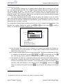
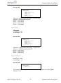
One Hop Test
The One Hop test is a very useful test in systems that require a repeater in between two
nodes. The IHD will operate as a repeater (RTR) between the HHT and GAS. All messages from the
HHT which are directed towards GAS will be relayed by the RTR. This test will help finding the best
possible location for the repeater to be placed and simultaneously tests the link between nodes
through the repeater. The following configuration screen is displayed when the one hop test option
is selected. The configuration screen allows the operator to modify the test parameters like Tx
Power, RSSI threshold, Channel used for test and the duration of test. To scroll through list of
parameters, use
press
and
arrow keys. Press
to edit,
and
to edit values and then
to set the parameter value for the current session of test.
One Hop Config
a
b
c
d
TX
RTH
CH
DUR
: xx dBm
: xx dBm
: xx
: xx sec
START
: xx Editable values
:xx:
xx
a. Transmit Power
b. RSSI Threshold
c. Channel for test
d. Duration of test
Figure 15 One hop configuration screen
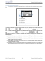
Once parameters are set navigate to the start button on the screen and press
to start
the test. At this point the one hop results screen as shown below will be displayed on screen.
Depending on the test state one of the following result screens will be displayed.
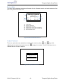
Screen-1
Screen-2
One Hop Results
HHT
RTR
One Hop Results
g
SAT-B
HHT
LINK
SAT-B
LINK
f
h
XX
RSSI
a
RTR
PER : XX
XX
XX
XX
CH : XX
c
b
RSSI
dBm
PER : XX
XX Sec
d
XX
e
XX
XX
CH
: XX
XX
dBm
XX sec
RTR to SAT-B link broken
HHT to RTR link broken
Screen-3
One Hop Results
HHT
RTR
SAT-B
LINK
RSSI
XX
PER : XX
XX
XX
CH
: XX
XX
a.
b.
c.
d.
e.
f.
g.
h.
RSSI at HHT from RTR
RSSI at RTR from HHT
Overall Packet Error Rate.
Channel on which test is being conducted.
RSSI at RTR from SAT-B.
RSSI at SAT-B from RTR.
Link between RTR and SAT-B.
Link between HHT and RTR.
dBm
XX sec
Note: in this test SAT-A will be used as RTR (repeater)
between HHT and SAT-B
One hop link established
©2012 Telegesis (UK) Ltd
Figure 16 One Hop Test Result Screens
-20-
Telegesis ZigBee RangeFinder
Telegesis ZigBee RangeFinder
Screen-1:
This is the initialization state of the test when there is no one hop link established between HHT and
GAS as shown in Screen-1. Initially when the devices (RTR or SAT) are out of range of the HHT or
are not turned on the HHT cannot pass on the message to the GAS. Hence the link status shows a
broken link between the HHT and RTR and GAS.
Screen-2:
The test will remain in the initialization state and periodically retry to establish the link (indicated by
periodic beeps). To run the test, turn on the RTR and bring it closer to the HHT until you see
Screen-2. When the HHT can communicate with RTR Screen-2 will be displayed which indicates
that the link between HHT and RTR is established but the link between HHT and GAS is not
established as the RTR cannot pass on the messages to the GAS. The HHT will try to continuously
establish one hop link until successful when screen 3 is displayed.
Screen-3:
When Screen-2 appears, turn on the GAS and bring it closer to the RTR so that it can get the
messages for the RTR. Once that happens Screen-3 will appear and the HHT will set the test
channel on all devices and start pinging messages to GAS for the set test duration and update the
RSSI values.
As the test is running the operator can move the devices to get a measure of the optimum range
between devices. If any of the devices move outside the pre-configured RSSI limits or if some
packets are missing the HHT will beep to indicate this and the operator can react accordingly.
To end the test press
key and the HHT will send a message to end the test on both RTR and
GAS units. Until both units are in range the end message will not carry forward to GAS and the HHT
will keep retrying which is indicated by periodic beeps on the HHT.
©2012 Telegesis (UK) Ltd
-21-
Telegesis ZigBee RangeFinder
Telegesis ZigBee RangeFinder
Device Configurations:
Single Satellite Configuration:
In some cases it may be necessary to run the test using only one Satellite unit. Such a
situation might exist where only an electricity meter is being installed together with an IHD. In such
cases it is possible to select the Satellite unit labelled IHD only to be used for test. To do so one has
to go to the Home Screen and scroll to (using
select between
revert to
or
and press
and
) item
and press keys
or
to
to save the setting. This setting is volatile and will
once the device is turned off.
©2012 Telegesis (UK) Ltd
-22-
Telegesis ZigBee RangeFinder
Telegesis ZigBee RangeFinder
Configuration Settings:
The Configuration Settings are the important device settings that are used by the HHT and
SAT units while performing the tests. The Telegesis Range Finder is designed to be able to simulate
any actual ZigBee SE device – such as IHD’s, GAS meters, ESI’s etc. All these devices may
operate at different power levels and may be able to operate at different RSSI thresholds in an
actual SE network. The Configuration Settings menu provides the way to introduce different settings
for different devices settings at the time of test.
There are 10 pre-stored device profiles that can be used by the operator on site. The values
within these settings cannot be changed without inputting a PIN number which is a 4 digit code. This
pass code can be restricted to authorised technicians to prevent accidental entering of incorrect
parameters by the operator in the field.
The Configuration Settings screen provides options for the user to change the test parameters. The
Operator can navigate through the options using
setting. The Configuration screen is shown below,
and
keys may press
to modify a
Configurations Settings
a
c
CDT
: 5 Sec
PIN : ****
b
PROFILES
c
d
e
HHT : DEV-PROFILE-01IHD : DEV-PROFILE-02GAS : DEV-PROFILE-10Editable values
(a) Countdown Timer
(b) Device PIN
(c) Profile settings for HHT
(d) Profile settings for IHD/SAT-A
(e) Profile settings for GAS/SAT-B
Figure 17: Configurations Screen
(a) The Countdown Timer value is set to a default of 5 seconds; the operator can change it to
values between 10 and 120 seconds. The change made is volatile and will revert back to the
default value1 after power-off.
(b) A four digit PIN code allows access to advanced settings. The factory programmed PIN code
is 1985 which can be entered using keys ,
,
and
and submitted using the
key. This PIN can be reset to default or changed to a new PIN via a serial command.
(c) The Operator can select the configurations settings from previously stored settings. Memory
required for 10 profiles reserved in non-volatile memory. These profiles can be edited and
stored by PIN protected serial commands. To set configuration a particular settings from a
particular profile and navigate to the profile for device using
Then scroll through list of profile and press
profile.
1
,
, and then press
.
to set the device with settings from selected
The default CDT value can be changed in the advance configuration settings.
©2012 Telegesis (UK) Ltd
-23-
Telegesis ZigBee RangeFinder
Telegesis ZigBee RangeFinder
Advanced Configurations Settings:
The Advance Configurations Settings Screen is visible only after entering the correct device
PIN.
a
Adv. Config Settings
IHD
: xxxx
GAS : xxxxx
b
DEV-PROFILE-01c
d
e
CDT : xx sec
PN : xx
PI : xx msec
f
g
h
i
TX : xx dBm
RTH : xx dBm
PER : x %
Editable values
(a) IHD Serial Number
(b) GAS Serial Number
(c) Name of Profile to display
(d) Countdown Timer
(e) Ping Number
(f) Ping Interval
(g) Packer Error Rate
(h) RSSI Threshold
(i) Advanced
Transmit Power
Figure 18:
Configurations Screen
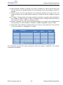
To display the settings of different profiles stored in the HHT navigate to the Profile section using
and
keys, then use
and
keys to scroll through the 10 profile settings stored into
HHT. To change a particular parameter of the displayed profile use keys
parameter and then press
to start modifying it using keys
,
,
to save the settings. To cancel the changes while modifying press
explained below.
,
to navigate to the
and
, and press
. The parameters are
(a) IHD Serial: Serial number of Satellite unit labelled as IHD. Only the Satellite with matching
serial number will be used in the test.
(b) GAS Serial: Serial number of Satellite unit labelled as GAS. Only the Satellite with matching
serial number will be used in the test.
(c) Profile Name: Is the name of the profile out of the 10 stored profiles, whose settings are
currently displayed on screen.
(d) Countdown Timer: This is the default setting of the Countdown time which is non-volatile and
will be used each time the unit is turned on. The valid limit for the timer is 5 to 120 seconds.
©2012 Telegesis (UK) Ltd
-24-
Telegesis ZigBee RangeFinder
Telegesis ZigBee RangeFinder
(e) Packet Number: Number of packets to be sent to a Satellite on a given channel during the
test, the selection is available between 50 to 100 packets and can be changed in steps of 5
packets.
(f) Packet Interval: The time gap between two consecutive packets sent during a test. The
minimum interval can be 10mS and the maximum is 25mS and can be changed in steps of
5mS.
(g) TX Power: Transmit power level while sending the packets, the power setting available is
from +8dBm to -9dBm in steps of 1dBm for standard version of Range Finder and values of
20,19,18,16,15,13,10,7,1 dBm for long range version
(h) Receive Threshold: The minimum receive signal strength for a packet to be considered valid
for test purpose. The limit available is -85dBm to -45dBm changeable in steps of 1dBm.
(i) Packet Error Rate: Maximum allowed packet error rate for a successful test. The limits are
2% to 10% maximum - changeable in 1% steps.
Label
Parameter
CDT
IHD
GAS
PN
PI
TX
RTH
PER
Countdown Timer
IHD Serial
GAS Serial
Packet Number
Packet Interval
TX Power
Receive Threshold
Packet Error Rate
Minimum
Value
5 Seconds
0000
0000
50
10mS
-9dBm
-85dBm
2%
Maximum
Value
120 sec
65535
65535
100
25mS
8dBm
-45dBm
10%
Change
Steps
1 sec
1
1
5
5mS
1dBm
1dBm
1%
Figure 19: Configurations Parameter Limits
The mechanism by which the above parameters affect the testing is explained in the section
“Interpreting Test Results”.
©2012 Telegesis (UK) Ltd
-25-
Telegesis ZigBee RangeFinder
Telegesis ZigBee RangeFinder
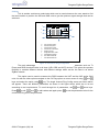
Firmware Upgrades:
The Telegesis Range Finder comes with an Over-The-Air (OTA) Bootloader. This enables
the HHT to upgrade its own firmware via the USB link and also remotely upgrade the firmware of the
SAT units. The Firmware Upgrades function is PIN protected for security.
Firmware Upgrade
Enter Device PIN
PIN : ****
Firmware Upgrade
Select device to upgrade
HHT
IHD
GAS
Once the device PIN is entered
Firmware
Upgrade screen will give the options
Figure 20correctly
Firmwarethe
Upgrade
Screens
to select a device to perform the upgrade.
Upgrading the HHT unit:
Select the HHT unit for upgrade by navigating to it and pressing
key. That will start the
bootloader in serial mode and the new firmware image can be transferred via Xmodem at 115200
8N1 baud using the Telegesis Terminal or any other terminal program that supports Xmodem. The
display on the HHT unit will show the following screen and the backlight will start to blink with red
and green lights indicating that the bootloader is active and waiting for new firmware image.
Bootload Mode Activated
PRESS
‘1’ : Start Xmodem
‘2’ : Run new firmware
Figure 21 HHT Firmware Upgrade
©2012 Telegesis (UK) Ltd
-26-
Telegesis ZigBee RangeFinder
Telegesis ZigBee RangeFinder
Now Press Enter key on host PC to get the
bootloader options on the terminal as shown in
the fig->
To upload the new firmware image press ‘1’
on the host PC, which will put the bootloader
in Xmodem receive mode.
Indicated by outputting ‘C’ on the terminal as
shown in the fig->.
Now Transfer the new firmware *.ebl file to the
HHT unit.
Once the file is transferred press ‘2’ on host
PC to run the new firmware.
Figure 22 HHT Firmware upgrade options
©2012 Telegesis (UK) Ltd
-27-
Telegesis ZigBee RangeFinder
Telegesis ZigBee RangeFinder
Upgrading the SAT units:
It is possible to perform OTA firmware upgrades of the SAT units. The upgrade image (*.ebl
file) will be passed to the HHT to send it across to the SAT unit. Select the IHD/GAS unit for
upgrade by navigating to the particular option on the Firmware Upgrade Screen and press
key.
That will start the bootloader in OTA pass-through mode and the new firmware image can be
transferred to the remote IHD or GAS unit over the air via HHT unit using Xmodem protocol at
115200 baud 8N1.
When the remote SAT unit is selected for OTA
firmware upgrade, the red LED starts flashing
continuously.
And the HHT outputs ‘C’ as shown in fig->
the terminal indicating that it expects the image
to be transferred to SAT unit.
Transfer the firmware upgrade *.ebl file to the
HHT using Xmodem and the HHT will send it to
the remote SAT unit.
When the new firmware image is being
transferred the red LED on the SAT unit stops
blinking and the green LED starts flashing.
If for any reason (eg. Battery on SAT dying
while transfer of file or ZigBee link broken), the
SAT unit will remain in the same bootload
mode with red LED flashing. The HHT will
timeout after 30 sec and send out a message
on the terminal as shown in fig->
The entire file needs to be transferred again to
the SAT unit.
Figure 23 SAT Firmware Options
©2012 Telegesis (UK) Ltd
-28-
Telegesis ZigBee RangeFinder
Telegesis ZigBee RangeFinder
Data Logging:
The test results of Test-A/B and Energy scan results will be automatically logged into an onboard serial flash of 8MBits if the data logging feature is included into the device. The results will be
stored along with the device configurations settings at the time of test. The Data Logging screen will
pop up at every turn-on just after the Start-up screen to give a chance for user to enter the site ID
before the start of tests. This screen can also be accessed via the data logger option on menu
screen 2. The logger will start with a new record and increment record counter every time the site ID
is changed.
Data Log Config
SITE ID
a
DEFAULT SITE ID1
EDIT
b
OK
MEMORY AVAIL
1024 KB
: xx
a.
b.
Editable values
Site ID or loacation of test (16
character alphanumeric field)
Available storage
Figure 24 Data Logger Screen
Record Main Header
The record header will be of following type:
//Record size
int16u recordSize;
//Main record header
typdef struct {
int8u recordSiteId[16];
int16u recordMainNumber;
}recordMainHeader;
Where,
recordSize – This is the total size of data collected at each site location.
recordSize is the addition of the recordMainHeader bytes; recordSubHeader
bytes; records. Since there can be any number of tests performed at any given
site, the recordSize is variable hence it is calculated at the end of the last test
carried out at the site (i.e. when the new site ID is entered by the user). But it is
stored at the start of each record before the site ID in order to make scan through
records faster.
recordMainHeader – This is the main record header at the start of each set of
records collected at new site location.
©2012 Telegesis (UK) Ltd
-29-
Telegesis ZigBee RangeFinder
Telegesis ZigBee RangeFinder
recordSiteID[16] – This will be an 16 byte field used to store the site ID which
will be entered by the user manually through arrow keys on the HHT. The first 8
bytes of the Site ID will be fixed and can be used as a Start Of Record (SOR)
pointer.
recordMainNumber - It can be the Record ID or just a simple record counter
which increments after each record stored in the flash. This number will
increment when the test is done at new site location.
Record Sub Header
//Sub Record Header
Typedef struct{
int8u recordSubNumber;
int8u recordType;
int8u recordLength;
testSettings
recordTestSettings;
}recordSubHeader;
recordSubHeader – This header will be at the start of each individual record for
a test conducted at same site location.
recordSubNumber – The value recordSubNumber will indicate the record
number for the current site and will increment after each test performed at the
same site.
recordType – The one byte recordType identifier which will indicate which type
of test results is stored in the record field.
recordLength – This value will be the actual length of the record excluding the
record header bytes as the record header will be of fixed length.
recordTestSettings – This will be the configuration settings set in the HHT at
the time of current test.
Record Structures
Test A record
Sub Header
recordType – 0x01
recordLength – 28
recordTestSettings –
©2012 Telegesis (UK) Ltd
//testSettings for Test A and Test B
Typedef struct{
int8u PingNumber;
int8u PingInterval;
int8u perThreshold;
int8s transmitPowerHHT;
int8s transmitPowerA;
int8s transmitPowerB;
int8s rssiThresholdHHT;
int8s rssiThresholdA;
int8s rssiThresholdB;
}testSettings;
-30-
Telegesis ZigBee RangeFinder
Telegesis ZigBee RangeFinder
Record data
//test Records for Test A
typedef struct{
int8u satARssi [4][2];
int8u satBRssi [4][2];
int8u perA[4];
int8u perB[4];
int8u testResult[4];
}recordTestARecords;
Column-0 – RSSI received at the SAT- A or GAS end
Column-1 – RSSI received by HHT
Row-0 – CH11 result
Row-1 – CH14 result
Row-2 – CH15 result
Row-3 – CH19 result
Test B record
Sub header
recordType – 0x02
recordLength – 21
Record Data
//test Records for Test B
typedef struct{
int8u satARssi[3][2];
int8u satBRssi[3][2];
int8u perA[3];
int8u perB[3];
int8u testResult[3];
}recordTestBRecords;
Column-0 – RSSI received at the SAT- A or GAS end
Column-1 – RSSI received by the HHT
Row-0 – CH20 result
Row-1 – CH24 result
Row-2 – CH25 result
Energy Scan Record
recordType – 0x03
recordLength – 16
Record Data:
//test Record for Test B
typedef struct{
int8u energy[16];
}EScanRecords;
The energy results array will hold the values of Energy scan on all the ZigBee
channels 11-26
©2012 Telegesis (UK) Ltd
-31-
Telegesis ZigBee RangeFinder
Telegesis ZigBee RangeFinder
Device Info
This menu option displays the device information like the firmware version and serial numbers of the
SAT units paired to the HHT unit.
RANGE FINDER
a
2.4GHz Zigbee
Network Surveyor
HHT : xxx
VER : xxx
IHD : xxx
GAS : xxx
Press Any Key
c
d
(a)
(b)
(c)
(d)
(e)
(f)
b
f
e
Product Name
Space for OEM Label
Serial Number of the HHT
Serial Number of SAT-A set to emulate IHD
Serial Number of SAT-B set to emulate GAS
Device Firmware version.
Figure 25: Device Information Screen
Adjust Contrast
This menu option lets user adjust the contrast of the screen by using
adjusting to the required contrast level press
indicate that the contrast is applied.
and
keys. After
to apply the contrast. The HHT will beep once to
Contrast Adjust
e
Use
to adjust contrast
eOne Hop Results
Figure 26: Adjust Contrast Screen
©2012 Telegesis (UK) Ltd
-32-
Telegesis ZigBee RangeFinder
Telegesis ZigBee RangeFinder
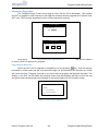
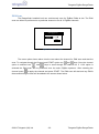
PAN Scan
The Rangefinder handheld unit can continuously scan for ZigBee PANs at site. The PAN
scan can either be performed on a particular channel or on all 16 ZigBee channels.
PANSCAN Options
e
Channel :
Options
e
11-26
eOne
HopSTART
Result e
s
Figure 27 PAN scan options
The menu option shown above lets the user select the channel for PAN scan and start the
scan. To navigate through the Channel and START option use
and
keys. Once the channel
option is selected use
and
keys to scroll through the channel list. If 11-26 option is
selected the PAN scan will be performed over the entire ZigBee spectrum. After selecting the
channel press
to apply the channel and press START. The PAN scan will start and any PAN’s
discovered during the scan will be added to the screen shown below.
©2012 Telegesis (UK) Ltd
-33-
Telegesis ZigBee RangeFinder
Telegesis ZigBee RangeFinder
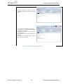
PAN Scan results screen
.
PAN’s found: 1 of 3
CH PANID JN JC RS W
eOne Hop
19 745F
Y Results
2 -43 |
20 6678
Y 2 -12 |
24 ABCD N 0 -23
Results
18
C234
N 2 -75
eOne Hop Results
CH
– ZigBee Channel number for the PAN found
PANID – PAN Id of the PAN found
JN
– Permit join state of the PAN found
Y if permit join is true
N if permit join is false
JC
– Join counter which increments each time the permit join
state changes from N to Y
RS
– RSSI value of the PAN
W
– Join window which changes its state automatically 2.5
minutes after the permit join status changes from N to Y
Once the PAN scan is started handheld unit will continuously scan and update the
information about PANs found on the screen. As many as 50 PANs can be discovered using this
tool. The PAN list will update dynamically when the new PAN is found. The network found with
permit join true is given higher priority in the list and will sit at the top of the list.
Pan change indications
Once a new network is found with permit join true OR if an existing network changes it
permit join state from N to Y, the HHT will beep 5 times and flash blue backlight for
indication.
If a new network is found with permit join false, it will be added to the list just after the
existing PANs with permit join true, there will not be any indication for the new network found
with permit join false, however if an existing network changes its state from Y to N, a long
beep of 5 sec along with red backlight flash will indicate this change.
After 2.5 minutes of permit join turning to Y the join window indicator will turn ON and HHT
will beep 5 times and flash blue backlight just as when a new PAN with permit join is
detected to indicate that the permit join is still true on the network to make the operator
aware of extended join window opening.
©2012 Telegesis (UK) Ltd
-34-
Telegesis ZigBee RangeFinder
Telegesis ZigBee RangeFinder
Power
The HHT is powered by rechargeable NiMH batteries which are charged through the USB
connection.
Batteries
The unit takes two 1.2 V 2000mAH NiMH batteries. To conserve the power consumption the unit will
turn itself off after a period of inactivity. The battery compartment is accessible on the back side of
the HHT and can be opened using a coin as shown in the Layout section. The battery compartment
is designed to take 3 AA cells hence the extra space is blanked off using a dummy pass-through AA
cell which should not be removed. The battery state is shown on the Home screen using the
following symbol,
Figure 28: Battery Symbol
The above symbol is showing 50% battery charge remaining.
Charging
The HHT can be charged or powered using the USB port connection. The USB connector is a USB
“B” Micro socket. The detection of the USB power source is indicated by a beep from the built-in
buzzer. The HHT does not go to sleep while it is powered from USB power source. The charger
charges the 2000mAh batteries at C/10 rate and it terminates the charge via voltage detection and a
12 hour timer. The power requirement for charging as well as operating the unit is 1.5Watts at 5
Volts. The charging state is shown on the Home screen by showing the following the symbol,
Figure 29: Battery Charging Symbol
The charging symbol shown above is replaced with the battery capacity remaining symbol as shown
in Figure 28: Battery Symbol once the charging is finished.
Power Saving
The HHT incorporates several ways to reduce power consumption and extend battery life. Most of
the power is consumed by the LED backlight for the screen so it is important to turn off the backlight
when not needed; the backlight is turned off in the following instances:
a) No key press by the operator for 10 seconds
b) 60 Seconds after a test has been completed
Moreover the unit is turned off after a period of inactivity of 15 minutes to save power. This 15
minutes is counted from the time the unit is turned on using the
and will be extended by 5
minutes if the user presses a key or a test is underway and the unit is in the last 5 minutes of the 15
minute wake period.
©2012 Telegesis (UK) Ltd
-35-
Telegesis ZigBee RangeFinder
Telegesis ZigBee RangeFinder
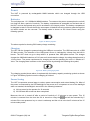
Satellite Unit
Layout
(a)
(c)
(b)
Figure 30: Satellite Front
(a) Model number: SAT100
(b) Power Button to turn the unit On or Off
(c) Red/Green LED to indicate the operation state of the unit
(a
)
(b
)
(c
)
Figure 31: Satellite Back
(a) SMA connector for Antenna
(b) Product Label
(c) Battery Compartment
©2012 Telegesis (UK) Ltd
-36-
Telegesis ZigBee RangeFinder
Telegesis ZigBee RangeFinder
(a)
(b)
(c)
(i)
(d)
(e)
(h)
(f)
(g)
Figure 32: Satellite Product Label
(a)
(b)
(c)
(d)
(e)
(f)
Product name
Module number of Satellite (SAT100)
Serial number of the product
Operating parameters of the product
Warning
Barcode with following content:
<Model>/L<Serial>
e.g. ‘SAT100/L157’
(g) Manufacturer’s contact information
(h) Compliance marking for CE and WEEE
(i) Manufacturer’s logo
Functionality
The Satellite units (IHD/B) are always listening to commands from the HHT to which they are
paired to and respond with the information required to calculate the results for various tests
performed by the HHT. There is an ON/OFF button for power ON/OFF and status LED’s for SAT
activity indication.
Buttons
There is only button on the Satellite which is the Power Button as shown in Figure 296. The Power
Button needs to be pressed down for 3 seconds for it to take effect. When the Power Button is
pressed, the LED indicator turns to solid RED colour and then turns off completely if the power is
switched off or changes to flashing Red or Green if it is turned on.
LEDs
The indicator LED has two colours and it can represent following states for the Satellite.
Red LED
ON
OFF
Flashing
1 flash/sec
Flashing
2 flash/sec
ON
Green LED
OFF
Flashing
1 flash/sec
OFF
OFF
Flashing
2 flash/sec
Satellite State
Power Button is pressed.
SAT unit ON and Battery
State healthy.
SAT ON and Battery Low.
SAT unit waiting for upgrade
image.
SAT receiving new image
from HHT
Figure 33: Satellite LED States
©2012 Telegesis (UK) Ltd
-37-
Telegesis ZigBee RangeFinder
Telegesis ZigBee RangeFinder
Power
Batteries
The Satellite is powered by two 1.5 V AA Alkaline batteries. The battery state is indicated by the
flashing Red for low and flashing Green for good battery state. The percentage battery capacity
remaining is also sent to the HHT as part of the Pre-Test and is shown on the Pre-Test screen (see
Figure 7).
Power Consumption
To conserve the power the Satellite units are turned off after 15 minutes of wakeup period. If the
Satellite receives any radio message from the HHT in the last 15 minutes of the wakeup period then
it extends the wakeup period by 5 more minutes.
Nominal power consumed by the Satellite while it is turned on is 100mW.
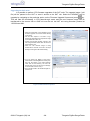
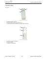
Usage
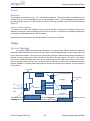
System Topology
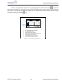
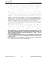
In a typical ZigBee Smart Energy installation it is expected the Electric and Gas meter will
always be static whereas the IHD can move around. It is also expected that in some cases there will
be no Gas meter present. This gives us the Electricity meter as a static element which will always be
present. In many cases this is also the ESI for the Smart Energy network. The HHT is the centre
point of the ZigBee RangeFinder and all the measurements are made with respect to the HHT,
hence it makes sense to put the HHT in place where the Electricity meter will be installed and place
the two Satellites in location where IHD and Gas meter are expected to be placed. A typical setup is
shown below,
Point D
Point C
BT Home Hub
Gas Meter
Garage
TV
Point B
STB
Electricity Meter
iTV
Kitchen
Figure 34: A typical floor plan with Smart Energy equipment
locations
A the IHD can be in any location such as
The Electricity and Gas meter locations are fixed Point
whereas
Lounge by points A,B,C and D in the above floor plan.
indicated
©2012 Telegesis (UK) Ltd
-38-
Telegesis ZigBee RangeFinder
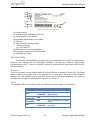
Telegesis ZigBee RangeFinder
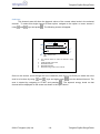
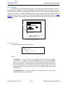
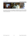
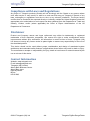
Figure 35: RangeFinder locations: Electric meter, Gas meter and Kitchen work surface
In the above picture the HHT is placed adjacent to the Electricity meter; the Satellite unit labelled
GAS is placed on the GAS meter and the Satellite unit labelled IHD is placed on the kitchen work
surface. The tests are then run on the HHT to make sure that all simulated devices will be able to
communicate with each other.
©2012 Telegesis (UK) Ltd
-39-
Telegesis ZigBee RangeFinder
Telegesis ZigBee RangeFinder
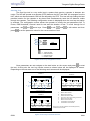
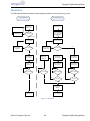
Workflow
The following flowchart shows the expected procedural flow for performing a test.
Flashing Red
Flow at Satellite Unit
Turn Power Off
Change Batteries
Flow at Handheld Unit
Power On
IHD and GAS
Satellite Units
Power On
Handheld Unit
Observer LED
Flashing
From Main Menu
select ‘I’ for IHD only
and ‘IG’ for both IHD
and GAS satellite
units
Flashing Green
Perform Pre-Test
on the Handheld
Perform Pre-Test
Yes
Bring Closer to
Handheld
No
Bring Closer to
Satellite Units
Pre-Test Pass
No
Pre-Test Pass
Yes
Start Energy
Scan on the
Handheld
Place Satellite in
Test Location
Start Test on the
Handheld
Start Test B on
the Handheld
Start Test A on
the Handheld
Place Handheld in
Test Location
Place Handheld in
Test Location
Yes
No
No
Test Completed
Yes
Test Completed
Yes
Test Completed
No
No
No
No
Test Completed
Yes
Yes
Test Pass
Test Pass
Yes
Yes
Record Test
Results
Turn Power Off
Turn Power Off
Figure 36: Workflow
©2012 Telegesis (UK) Ltd
-40-
Telegesis ZigBee RangeFinder
Telegesis ZigBee RangeFinder
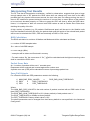
Interpreting Test Results
The RF over-the-air transmission mechanism, verified by observation, suggests that given a large
enough sample size of RF packets the RSSI value does not change any more than a few dBm
provided that the physical environment around the test units does not change during the test. If
there is RF interference present during the test then it is more likely to cause failure of the packets
to be received, decoded properly or a failure to pass the CRC test than to affect the RSSI value.
Hence, it is important to take into account both RSSI values as well as Packet Error Rate when
deciding the quality of the link.
A high number of packets (e.g. 50 packets 10millisecond apart) will be sent to the Satellite units
from the Handheld unit which will echo the packets back and the results of the echoed-back packet
will be used to calculate the RSSI , PER and eventually a PASS or FAIL result.
RSSI Calculation
The RSSI calculation is a mixture of Median and Mode and will be calculated as follows,
n = number of RSSI samples taken
Sn = value of nth RSSI sample
e = error margin (dBm)
* n samples will be taken and Sn stored in memory
* For each unique ‘Sn’ the occurrence of ‘Sn
shall be used as the RSSI value
will be calculated and the highest occurring value
Packet Error Rate
An ‘n’ number of packets will be sent ‘t’ seconds apart
Responses will be received and counted against the number sent
A packet error rate (PER) will be calculated in terms of percentage packet loss
Pass/Fail Criteria
For a Pass the RSSI and PER parameters needs to be following,
1) NUM_BAD_RSSI_VALUES
<
2) RSSI
>
RSSI_THRESHOLD
3) PER
<
PER_THRESHOLD
RSSI_BAD_NUM_THRESHOLD
Where:
The NUM_BAD_RSSI_VALUES is the total number of packets received with an RSSI value of less
than RSSI_THRESHOLD
The RSSI_BAD_NUM_THRESHOLD is 10% (factory default) of total packets sent ‘n’
The RSSI_THRESHOLD is -85dBm as factory default
The PER_THRESHOLD factory default value is 10%
The above parameters can be changed from their factory default to user-specified in the Advanced
Config menu.
©2012 Telegesis (UK) Ltd
-41-
Telegesis ZigBee RangeFinder
Telegesis ZigBee RangeFinder
Warranty
1. Telegesis warrants that at the date of delivery the Goods will conform in all material respects
to any written specification published or provided by Telegesis and that for the periods set
out below in respect of each product type the Goods will be free from defects in
workmanship and materials under normal use and service. The Buyer must notify Telegesis
of any defect in writing. Telegesis's obligation under this warranty will not arise until the
Buyer returns the defective Goods at its own expense and risk, to Telegesis. Telegesis sole
obligation under this warranty shall be at its option to replace or repair without charge such
defective Goods or component parts thereof. Any replacement of Goods or component parts
under this warranty shall not extend the period of warranty beyond that of the goods or
component parts so replaced.
2. All Hardware is supplied with one year return to base warranty unless indicated otherwise.
All Software is supplied with a 90-day warranty period.
3. With respect to any computer software comprised in the Goods supplied by Telegesis any
defects arising after expiry of the warranty period referred to above should be notified to
Telegesis in writing, Telegesis may at its discretion endeavour to correct any such defects
but Telegesis gives no warranty that any such defects can be corrected or that defects will
be corrected within a particular time.
4. Telegesis shall not be liable hereunder:
a) If the Goods alleged to be defective have been repaired or altered by any person other
than Telegesis designated personnel or authorised representative or other person
approved by Telegesis in writing; or
b) Where testing or examination by Telegesis reveals any alleged defect in the goods to
have been caused by the buyers misuse, neglect, improper installation, failure to follow
instructions (whether oral or in writing), or the supply by the Buyer of incorrect or
inadequate instructions or information with the regards to the design of any Goods or to
have been caused by any similar equipment to which the Goods are attached or in which
the Goods are incorporated or any cause beyond the range of intended use of the Goods
or by accident, fire or other hazard; or
c) Where component parts alleged to be defective were not manufactured by Telegesis but
were included in the Goods at the request of the Buyer, in which case the Buyer shall
only be entitled to the benefit of any such warranty or guarantee as is given by the
manufacturer or supplier of such parts to Telegesis.
©2012 Telegesis (UK) Ltd
-42-
Telegesis ZigBee RangeFinder
Telegesis ZigBee RangeFinder
5. If the goods are to be manufactured or any process is to be applied to them by Telegesis in
accordance with a specification submitted by the Buyer, the Buyer shall indemnify Telegesis
against all loss, damages, costs and expenses awarded against or incurred by Telegesis in
connection with or paid or agreed to be paid by Telegesis in settlement of any claim which
results from Telegesis's use of the Buyers specification, including but not limited to any claim
for infringement of any patent, copyright, design, trade mark or other intellectual property
rights of any other person.
6. Telegesis's liability hereunder shall be in lieu of any other representation (unless fraudulent),
warranty or condition, expressed or implied by law or otherwise with respect to the goods or
any liability imposed by common law, statute or otherwise and Telegesis hereby excludes all
such representations (unless fraudulent), warranties and conditions and shall not be liable to
the Buyer for any loss or damage whatsoever (including without prejudice to generality of the
foregoing any liability in contract, negligence, or any other tort for indirect consequential or
economic loss or for loss of profit or opportunity of any kind) arising directly or indirectly in
connection with the contract, the Goods or otherwise except insofar as any exclusion or
limitations of Telegesis liability hereunder is prohibited, void or enforceable by law.
7. Telegesis shall not be responsible in any manner whatsoever for any software, information
or memory data stored on or integrated with any of the Goods returned to Telegesis for
repair or replacement under this warranty.
8. Without prejudice to any other provision in these Terms, in any event Telegesis's total
liability for any one claim or for the total of all claims arising from one act of default on
Telegesis's part (whether arising from Telegesis's negligence or otherwise) shall not exceed
the purchase price of the Goods the subject matter of any claim but nothing herein shall limit
or exclude Telegesis liability for death or personal injury caused by Telegesis's negligence or
Telegesis's liability for fraudulent r misrepresentation.
9. Where the buyer deals as a consumer within the meaning of the unfair contract Terms Act
1977 nothing in these terms shall restrict or exclude any liability of Telegesis for breach of its
implied undertakings as to conformity of the goods with description or sample or as to their
quality or fitness for the purpose.
10. In the case of a consumer transaction nothing in these terms sham affect the statutory rights
of the Buyer as defined in the Consumer Transaction (Restrictions on Statements) Order
1976 (as mentioned).
11. The period or terms of the warranty contained in this clause shall only be varied or extended
where Telegesis has granted the Buyer an Extended Warranty.
©2012 Telegesis (UK) Ltd
-43-
Telegesis ZigBee RangeFinder
Telegesis ZigBee RangeFinder
Compliance with Laws and Regulations
Any Buyer of Telegesis products (Goods) will not knowingly sell the Goods to any person where
such sale may be or may result in a sale to an end user that may put Telegesis in breach of any
laws, embargoes or regulations from time to time or any relevant jurisdiction. The Buyer hereby
certifies that no Goods will be exported directly or indirectly outside the United Kingdom unless the
appropriate prior authorisation to such export has been obtained from the Department of Trade and
Industry, London, and/or (where applicable) the Office of Export Administration of the US
Department of Commerce.
Disclaimer
Product and Company names and logos referenced may either be trademarks or registered
trademarks of their respective companies. We reserve the right to make modifications and/or
improvements without prior notification. All information is correct at time of issue. Telegesis (UK)
Ltd. does not convey any license under its patent rights or assume any responsibility for the use of
the described product.
This device should not be used without proper consideration and design of associated system
architecture and redundant safety features in applications where failure may result in death or injury.
The manufacturer accepts no responsibility for injury, death or loss human or material caused by the
use or misuse of this device
Contact Information
Website: www.telegesis.com
E-mail [email protected]
Telegesis (UK) Limited
Abbey Barn Business Centre
Abbey Barn Lane
High Wycombe
Bucks
HP10 9QQ
©2012 Telegesis (UK) Ltd
-44-
Telegesis ZigBee RangeFinder