1
VRVision User Manual
Version 1.07
James Ward
University of Hull, UK
20th May 2003
Last updated: 1st August 2004
All trademarks acknowledged.
TABLE OF CONTENTS
1. Introduction .......................................................................................................................................... 1
2. Requirements........................................................................................................................................ 2
2.1. Software Requirements ................................................................................................................. 2
2.2. Hardware Requirements ................................................................................................................ 2
3. Installation............................................................................................................................................ 3
4. Getting Started...................................................................................................................................... 4
5. Function Reference .............................................................................................................................. 5
5.1. Setup Functions ............................................................................................................................. 5
SetFilename...................................................................................................................................... 5
SetModifier ...................................................................................................................................... 5
SetViewPos ...................................................................................................................................... 6
SetScenePos ..................................................................................................................................... 7
SetScale ............................................................................................................................................ 7
SetAngleX ........................................................................................................................................ 7
SetAngleY ........................................................................................................................................ 7
SetBackCol....................................................................................................................................... 7
UseStereo ......................................................................................................................................... 8
UseHeadTrack.................................................................................................................................. 8
UseTimeLimit .................................................................................................................................. 8
UseQuitKeys .................................................................................................................................... 8
UseMouseMove ............................................................................................................................... 9
UseJoyMove..................................................................................................................................... 9
UseJoyQuitKeys............................................................................................................................... 9
UseFullScreen ................................................................................................................................ 10
UseUnderlay................................................................................................................................... 10
RecordToFile.................................................................................................................................. 11
PlayFromFile.................................................................................................................................. 11
DumpPos ........................................................................................................................................ 11
5.2. Query Functions .......................................................................................................................... 11
GetQuitKey .................................................................................................................................... 11
GetQuitKeyTime ............................................................................................................................ 12
6. Scene Files ......................................................................................................................................... 13
6.1. Lighting ....................................................................................................................................... 13
Directional Light ............................................................................................................................ 13
Point Light...................................................................................................................................... 13
Spot Light....................................................................................................................................... 14
Common Light Properties .............................................................................................................. 15
Material Properties ......................................................................................................................... 15
Multiple Light Sources................................................................................................................... 16
Base Colour Lighting ..................................................................................................................... 16
Animated Light Sources................................................................................................................. 17
6.2. The Scene Graph ......................................................................................................................... 17
Default Scene Graph ...................................................................................................................... 17
Rotate First Option ......................................................................................................................... 18
6.3. The Open Inventor File Format ................................................................................................... 18
Example 1: Creating a Cube........................................................................................................... 18
Example 2: Transformations .......................................................................................................... 19
Example 3: Using Separators ......................................................................................................... 20
Example 4: Complex Surfaces ....................................................................................................... 21
7. Initialisation File ................................................................................................................................ 22
7.1. [Screen] ....................................................................................................................................... 22
7.2. [Camera]...................................................................................................................................... 23
7.3. [Tracker]...................................................................................................................................... 24
7.4. [TrackerXForm] .......................................................................................................................... 25
7.5. [GlassesXForm] .......................................................................................................................... 26
7.6. [Scene]......................................................................................................................................... 26
7.7. [Joystick] ..................................................................................................................................... 29
8. Hardware for Stereoscopy .................................................................................................................. 30
8.1. Display Devices........................................................................................................................... 30
Shutter Glasses ............................................................................................................................... 30
Monitors ......................................................................................................................................... 31
8.2. Graphics Cards ............................................................................................................................ 31
The 3DLabs Wildcat family ........................................................................................................... 32
The nVidia Quadro/GeForce family............................................................................................... 32
9. Tracking Systems ............................................................................................................................... 35
9.1. Supported Tracking Systems....................................................................................................... 35
9.2. Configuration File Settings.......................................................................................................... 35
Sample: Logitech 3D Mouse .......................................................................................................... 35
Sample: Ascension Flock of Birds ................................................................................................. 36
1. Introduction
VRVision is a MEX plug-in for Matlab, which allows 3D scenes to be displayed in real-time,
with controllable lighting, perspective and photo texturing. Scenes can be presented in true
stereoscopic 3D, and with a dynamic viewpoint that accounts for the head position of the
viewer. It directly supports VRML1 and OpenInventor file formats, and other formats can be
read by using third party file converters.
The software was originally designed for use by Psychologists in behavioural research
experiments. It was conceived as a replacement for databases of pre-rendered 2D images that
were typically prepared using packages such as 3D Studio MAX (Discreet) or Maya (Alias
Wavefront). With VRVision, it is possible to display 3D scenes in real-time, and to vary the
conditions (such as lighting, orientation, texturing, animation) during the course of an
experiment. This can be achieved without the need to generate large databases of images, and
can therefore save a lot of time and effort on the part of the researcher.
VRVision was designed for use with existing software such as Matlab and the PsychToolbox,
which have become popular for this type of study.
1
2. Requirements
2.1. Software Requirements
The basic requirements are as follows:
Operating System:
Windows 2000 (recommended) or Windows XP
Matlab Version:
Matlab 6.1 or greater
Optional Software:
Psychophysics Toolbox (PsychToolbox)
The current version of VRVision has been developed on Windows 2000, and has also been
used successfully on Windows XP. Other versions of Windows such as 95/98/ME/NT have
not been tested, and are not recommended. The VRVision software is reasonably portable,
and we plan to develop versions for other operating systems (MacOS X, Linux) in the future.
The development work was carried out in Matlab 6.1, and the software has also been tested in
Matlab 6.5. Later versions of Matlab are probably compatible, but are untested at time of
writing.
It is recommended that you download and install the excellent PsychToolbox, since this will
give you the most flexibility when constructing experimental programs. It is then possible to
use PsychToolbox to display 2D images and user interface displays, then use VRVision to
display 3D scenes and for stereoscopic display as appropriate. It would equally be possible to
use the Matlab windowing system to construct user interfaces, but you might find
PsychToolbox more suitable (for example, it is difficult to make true full screen windows
with Matlab).
2.2. Hardware Requirements
The hardware requirements are highly dependent upon which features of VRVision you wish
to use. The program should be usable in its basic form on most PCs. However, if you wish to
display complex 3D scenes (thousands of polygons, texture maps etc.), then a reasonable
minimum specification is:
Pentium III 1GHz CPU
256Mb RAM
nVidia GeForce 2 MX graphics card (note: does not support stereoscopic display)
If you wish to use the stereoscopic display feature, then you will also need a graphics card
that supports quad-buffer OpenGL stereo, and an appropriate display device. For more details,
please refer to Section 7, which covers the topic in more detail.
Similarly, if you wish to use the head tracking feature, then you will need access to one of the
tracking systems that are supported by VRVision which are listed in Section 9.
2
3. Installation
The VRVision software can be downloaded from the web-site as single ZIP file, which
contains all the files needed to get you started. You can download the software from the
following address:
http://www.hive.hull.ac.uk/software/vrvision
Having downloaded the software, you can unzip all the files into the Matlab\work folder, and
restart Matlab. If you don’t want to place these files in your work folder, you can create a new
folder and alter the Matlab search path accordingly.
The following is a step by step installation example:
1. Download the complete VRVision software as a ZIP file.
2. Unzip the files into the Matlab working directory. You can install them in another
directory if you wish, but make sure that it is in the Matlab search path.
For example:
c:\matlab6p5\work
3. Restart Matlab to make sure that the vrvision module is loaded.
VRVision itself is a standard Matlab MEX file, which consists of a Windows DLL. This DLL
must be in the Matlab MEX search path, so that it is found when ‘vrvis’ is typed at the Matlab
prompt. The ZIP file includes a number of other DLL files that are needed by VRVision, as
well as an initialisation (INI) file and a sample scene. It is important that all the files are
installed, otherwise VRVision will not load.
The INI settings file must be placed in the same working directory as the VRVision DLL.
However, the remaining files can be placed anywhere in the Windows search path. For
example, you can place them in the Windows system directory or create a new folder and add
it to the Windows search path.
After changing file locations and search path settings, it might be necessary to restart Matlab
for the changes to take effect.
3
4. Getting Started
For those who dislike reading lengthy instructions, here is a very brief introduction to get you
started:
1. Install VRVision as described in Section 3.
2. Obtain an OpenInventor or VRML 1.0 model (file extension .iv or .wrl).
There are some sample files provided on the web-site:
http://www.hive.hull.ac.uk/software/vrvision
Note that VRML97 / VRML 2.0 are not currently supported by SGI
OpenInventor.
3. Your scene may be too big or too small to display by default, or it may be
positioned far away from the origin. Also, if your scene doesn't contain
lights, you should turn on the headlight.
For these reasons, when running VRVision for the first time you might
want to use a text editor (e.g. notepad) to edit some of the settings in the
'vrvision.ini' file to match the ones shown here:
[Scene]
Headlight=1
Scale=auto
AutoCentre=1
; turn on the headlight
; use automatic scaling
; automatically move scene to origin
4. Start Matlab normally.
5. Instruct VRVision to load the scene, and display it:
>> vrvis(‘SetFilename’, ‘yourscene.iv’)
>> vrvis
If that was successful, you will find the other supported functions documented in Section 5.
The best way to understand what is possible, and how to use the supported functions, is to
work through the different commands in the function reference at a Matlab command prompt.
In this way, you can immediately see the effect of the different options on the behaviour of
VRVision.
4
5. Function Reference
This section lists the functions supported by VRVision, explains their parameters, and
provides some examples of how they can be used in practice. All the examples shown here
are typed at the Matlab prompt, or called from within a Matlab program (M file).
There are two ways that VRVision can be called. The first one is to call the main function
without any parameters. You can either use the full name of the function ‘vrvision’ as shown
here:
>> vrvision
Alternatively, you can use the shorthand:
>> vrvis
This will start the main VRVision application, and display the current 3D scene. However,
before doing this you would normally need to set up some parameters, for example to specify
which scene file to load. There are a number of functions provided for this purpose.
Every function consists of a call to VRVision, with the name of the function passed as a text
string, followed by an optional list of parameters. For example, to call the SetFilename
function:
>> vrvis(‘SetFilename’, ‘myscene.iv’)
Functions fall into two main categories:
1. Setup: functions that set parameters, before running VRVision.
2. Query: functions that retrieve data or results after VRVision has finished running.
5.1. Setup Functions
These functions can be called before the application runs, to configure various settings, such
as which scene file to load or the viewer position. Most of these settings will persist between
successive runs of VRVision, unless stated otherwise. Many of them are also configurable
from within the INI file, in which case the INI file setting acts as a default that is overridden
when you change the setting from within Matlab.
SetFilename
Specifies which 3D scene file should be loaded when VRVision runs. If no file is specified,
the filename given in the INI file will be used instead. The current version directly supports
files with the following formats:
VRML 1.0
OpenInventor 2.1 (ASCII or binary)
Examples:
vrvis('SetFilename', 'filename.wrl')
vrvis('SetFilename', 'filename.iv')
vrvis('SetFilename', 'samples/robot.iv')
Note: the path separator is '/', for example: 'folder/file.iv'.
SetModifier
You can specify an optional modifier to the 3D scene. The modifier is simply another
Inventor/VRML file that is loaded immediately before the 3D scene (in technical terms, the
5
3D scene becomes a child node of the modifier). Therefore, any Inventor nodes in this file
will affect the scene.
This is mainly a convenience for the user, since the same scene file can be loaded under a
number of different modifiers to achieve different results. This is a very powerful feature, and
has many possible applications:
•
•
•
•
Animation. For example, to make a scene rotate automatically.
Lighting. For example, to view the same scene with different lighting conditions.
Resize / Reposition. Scale or translate the scene before display.
Display styles. For example, to modify the draw style: wireframe, points etc.
It is probably simpler to explain this with an example:
1. Create a text file called ‘wire.iv’ containing the following text:
#Inventor V2.1 ascii
DrawStyle {
style LINES
}
You can use any text editor to do this (notepad for example).
2. Set up VRVision to use this as a modifier:
vrvis(‘SetModifier’, ‘wire.iv’)
3. Now, when you use VRVision normally to display a scene:
vrvis(‘SetFilename’, ‘yourscene.iv’)
vrvis
You should see that the scene is displayed in wireframe.
The proper use of modifiers can simplify the process of setting up several different
experimental conditions without modifying the scene file itself. For example, in a face
recognition study, the scene files would contain the VRML face models, and the modifiers
might specify different lighting conditions.
Some understanding of OpenInventor or VRML nodes is needed to be able to make the best
use of this feature.
SetViewPos
Sets the default viewer position (X,Y,Z coordinates in metres). This will be used in preference
to the value given in the INI file under the [Camera].Position key (the INI file settings are
explained in more detail in section 7). If head tracking is enabled, the viewer position is
controlled by the tracking system instead.
This setting will typically be used when the viewer is always in a fixed viewing position, for
example when seated in front of the screen, or if a chin rest is used to position the head.
If you call 'SetViewPos' without arguments, it restores the default setting from the INI file.
The origin (0,0,0) is the centre of the screen. From the point of view of the user, the X axis
points right, the Y axis up, and the Z axis points out of the screen.
For example, to place the viewer 2m distant from screen:
vrvis('SetViewPos', 0,0,2)
To restore the INI default setting, call the function without any parameters:
vrvis('SetViewPos')
6
SetScenePos
Specifies the scene position, as an X,Y,Z translation in metres. If the AutoCentre option is
enabled (in the INI file) this translation will be applied after the auto-centre. Therefore, you
can combine these two options. However, if you want to specify an absolute translation for
the object in world coordinates, you should ensure that AutoCentre is first disabled (otherwise
your translation will be made relative, after the object has first been moved to the origin).
For example, to move the object 1m behind the screen (assuming that it is normally located at
the origin):
vrvis('SetScenePos', 0,0,-1)
The origin (0,0,0) is the centre of the screen. From the point of view of the user, the X axis
points right, the Y axis up, and the Z axis points out of the screen.
SetScale
This function sets the scene scale factor. This will be used in preference to the value given in
the INI file. For example, to set an absolute scale of 1/10th normal size:
vrvis('SetScale', 0.1)
The size on screen may be affected by the following:
•
•
•
•
Object dimensions in the scene file.
Screen size settings in the INI file.
Scale factor (either from INI file, or the SetScale function).
The viewer / object position relative to the screen.
SetAngleX
Applies a rotation about the X-axis (right axis), given an angle in degrees. The rotation angle
can be positive or negative.
For example, to rotate the scene by 45 degrees:
vrvis('SetAngleX', 45)
This function is a convenience to the user. If you want to perform more general, or more
complex, transformations then an alternative is to use the modifier feature (see SetModifier
function for details).
SetAngleY
Applies a rotation about the Y-axis (vertical axis), given an angle in degrees. The rotation
angle can be positive or negative.
For example, to rotate the scene by 45 degrees:
vrvis('SetAngleY', 45)
This function is a convenience to the user. If you want to perform more general, or more
complex, transformations then an alternative is to use the modifier feature (see SetModifier
function for details).
SetBackCol
This function allows the background colour of the scene to be changed. The default is to use a
black background. The colour is specified as three values: Red, Green and Blue, each in the
range zero to one.
7
Examples:
vrvis('SetBackCol', 1,1,1) ; white background
vrvis('SetBackCol', 0.5,0,0)
; medium red background
vrvis('SetBackCol', 0,0,0) ; black background
Note: if you enable the underlay mode (see documentation of UseUnderlay function), the
background colour will be ignored.
UseStereo
This function determines whether the application should run with or without stereoscopic
display (for example, using LCD shutter glasses). Not all hardware is capable of running in
stereo. If stereo is not supported, VRVision defaults to the normal mono display mode.
Examples:
vrvis('UseStereo', 1)
vrvis('UseStereo', 0)
; enable stereo (if possible)
; disable stereo (the default)
For more details about the hardware requirements for stereo support, please refer to Section 7.
UseHeadTrack
This function enables head-tracking, if a suitable tracking system is first connected and
properly configured. When enabled the display is continuously updated to provide an
appropriate view for the current head position of the viewer. In particular, if stereo mode is
also enabled, the left and right eye positions of the viewer are calculated and used to provide
two different projections (using an asymmetric viewing frustum). Please refer to Section 9 for
further details.
Examples:
vrvis('UseHeadTrack', 1)
vrvis('UseHeadTrack', 0)
; enable head tracking
; disable head tracking
UseTimeLimit
Specifies a time limit in seconds, after which the application will automatically close. This
can be used to display a particular 3D scene for a limited time period.
Examples:
vrvis('UseTimeLimit', 12.5)
vrvis('UseTimeLimit', 0)
; display for 12.5 seconds
; disable the time limit
UseQuitKeys
This function allows you to specify which keys can be used to quit from the application.
When the application quits, it will return to Matlab. The default is to disable quit keys, except
for the ESC key (which can always be used to quit).
You can specify a character string, listing the acceptable quit-keys, or you can specify the
special string 'any' which will accept (almost) any key on the keyboard.
Examples:
vrvis('UseQuitKeys', 'abcdef')
vrvis('UseQuitKeys', 'any')
vrvis('UseQuitKeys', 0)
; quit when keys A-F pressed
; quit when "any" key pressed
; disable keyboard quit
8
If the user quits by pressing a key, it is possible to find out the elapsed time and the key that
they pressed using the following two functions:
GetQuitKey
GetQuitKeyTime
UseMouseMove
This function allows you to rotate the scene using the mouse. If enabled, horizontal movement
of the mouse will rotate the scene about the Y axis (azimuth), and vertical movement will
rotate the scene about the X axis (elevation). The range of movement on each axis can be
specified in terms of a maximum angle. For example, specifying an angle of 45 degrees will
allow the model to be rotated between -45 and +45 degrees. You can lock a particular axis
(prevent rotation on that axis), by specifying an angle limit of zero.
Examples:
vrvis('UseMouseMove',
vrvis('UseMouseMove',
vrvis('UseMouseMove',
vrvis('UseMouseMove',
vrvis('UseMouseMove',
1)
0)
1, 45,0)
1, 0,45)
1, 15,15)
;
;
;
;
;
enable mouse movement
disable mouse movement
allow 45° rotation about X
allow 45° rotation about Y
allow 15° rotation about X+Y
Mouse rotation can be recorded to file and replayed later. Please see the RecordToFile and
PlayFromFile functions for further details.
UseJoyMove
This function allows you to rotate the scene using a joystick or trackball. Most devices that
appear as a standard game controller within Windows should be compatible with this option.
This function supports the same rotation angle limits as the UseJoyMove function, including
the ability to lock an axis by specifying an angle limit of zero.
When using the joystick for movement, you can also use the joystick buttons. Please see the
UseJoyQuitKeys function for details.
Examples:
vrvis('UseJoyMove',
vrvis('UseJoyMove',
vrvis('UseJoyMove',
vrvis('UseJoyMove',
vrvis('UseJoyMove',
1)
0)
1, 45,0)
1, 0,45)
1, 15,15)
;
;
;
;
;
enable joystick movement
disable joystick movement
allow 45° rotation about X
allow 45° rotation about Y
allow 15° rotation about X+Y
Joystick rotation can be recorded to file and replayed later. Please see the RecordToFile and
PlayFromFile functions for further details.
UseJoyQuitKeys
This function allows you to specify which joystick buttons/keys can be used to quit from the
application. When the application quits, it will return to Matlab. The default is to disable quit
keys.
You can specify a character string, listing the acceptable button numbers, or you can specify
the special string 'any' which will accept any button press on the joystick. Button numbers
range from 0 to 9 inclusive, with 0 being the first joystick button. The numbering of buttons
will vary from one joystick to another. Some joysticks provide a utility for reassigning
buttons at driver level.
9
Examples:
vrvis('UseJoyQuitKeys', '01')
vrvis('UseJoyQuitKeys', 'any')
vrvis('UseJoyQuitKeys', 0)
; quit if button 0 or 1 pressed
; quit when "any" key pressed
; disable joystick quit
If the user quits by pressing a key, it is possible to find out the elapsed time and the key that
they pressed using the following two functions:
GetQuitKey
GetQuitKeyTime
To distinguish the joystick buttons from any other key on the keyboard, these functions return
special names for each button ranging from ‘JOY0’ through to ‘JOY9’.
UseFullScreen
This allows you to select either full-screen mode, or to display in a window (which can be
moved or resized). The default is to run full-screen. When running in full-screen mode,
VRVision will force itself on top of all other windows.
Examples:
vrvis('UseFullScreen', 0)
vrvis('UseFullScreen', 1)
; run in a window
; enable full-screen
UseUnderlay
This function is used to enable a special 'underlay' mode, which causes the entire desktop
contents to be screen captured as VRVision starts. This screen capture is then used as a
background image when drawing the 3D scene.
For example, you can use the SCREEN function in PsychToolbox to draw some background
graphics, then enable the underlay mode and start VRVision. When VRVision starts, the 3D
scene will appear superimposed on top of the drawing that you did previously.
Examples:
vrvis('UseUnderlay', 1)
vrvis('UseUnderlay', 0)
; enable underlay mode
; disable underlay (the default)
When underlay is enabled, the screen is captured just before VRVision appears. Therefore,
you should do your drawing just before running VRVision. The underlay feature only really
makes sense when VRVision is running in fullscreen mode, otherwise the screen contents will
be displayed in a much smaller window.
VRVision uses one of two methods to display the underlay:
1. Texture map method.
2. Blitter method.
The quality and speed of the two methods will vary between different graphics card and
driver combinations. In fact, the texture map method may not work at all if your graphics card
cannot create texture maps at full screen resolution. Therefore, you should pick the method
which works best on your card. You can do this by modifying the INI file as described below.
Under the [Scene] section of the INI file, use either of the following keys:
UnderBlit=0
UnderBlit=1
; use texture map method (OpenGL texturing)
; use blitter method (OpenGL glDrawPixels)
If this option is missing from the INI file, the default is to use the texture map method.
10
RecordToFile
This option causes the camera movement and/or mouse movement to be recorded to file, so
that it can later be analysed or replayed. It is typically used in conjunction with head tracking.
For example, the data could later be used to examine the motion of the users head during a
particular task.
The function takes a single parameter: the filename to record to. If the file already exists, it
will be overwritten. If the 'PlayFromFile' option is also specified, then it will take precedence
over recording.
This function applies only to the next run of VRVision, after which recording is cancelled.
Therefore, if you want to record every time, you must specify this option prior to each run
(which would be necessary in any case, to avoid overwriting the last file).
Examples:
vrvis('RecordToFile', 'filename')
PlayFromFile
This option is used to play back camera or mouse motion that has previously been recorded to
file using the RecordToFile function. The function takes a single parameter: the filename to
play back.
This function applies only to the next run of VRVision, after which playback is cancelled. If
head tracking was enabled as well, the file playback will take precedence. Optionally, you can
specify 'quit' to make the application close at the end of playback.
Examples:
vrvis('PlayFromFile', 'filename')
vrvis('PlayFromFile', 'filename', 'quit')
DumpPos
This option forces the position and orientation data received from the head tracker to be
dumped to the text console within Matlab. This function is only really useful for a developer;
it is useful for debugging or calibrating the tracking system. For example, to calculate the
TrackerXForm or GlassesXForm parameters for the INI configuration file.
Examples:
vrvis('DumpPos', 1)
vrvis('DumpPos', 0)
; enable
; disable (default setting)
5.2. Query Functions
These functions are called after VRVision has finished displaying the scene, and returned
control to Matlab. They are used to retrieve information from VRVision, such as which key
was pressed to quit, or the elapsed time until the user hit the key.
GetQuitKey
This function returns the key that the user pressed to quit. It will only contain a valid key if
the key-quit option has first been enabled with the UseQuitKeys function. The key is returned
as a character array (string). To distinguish the joystick buttons from any other key on the
keyboard, they are named ‘JOY0’ through to ‘JOY9’.
Example:
k = vrvis(‘GetQuitKey’)
11
GetQuitKeyTime
This function returns the time in seconds that elapsed between the first drawing that the
application did (onset of stimulus), and the user pressing one of the accepted quit keys. The
resolution and accuracy are system dependent. There is more information about timing
accuracy on the VRVision web-site.
If the user didn't press a key, this function will return zero.
Example:
t = vrvis('GetQuitKeyTime')
12
6. Scene Files
This section briefly describes some of the effects that can be achieved by creating and editing
OpenInventor or VRML scene files.
6.1. Lighting
In common with most real-time graphics applications, VRVision uses a relatively simple
lighting model. This is sufficient for simple lighting effects, including directionality of light,
intensity and colour. It does not include effects such as shadows at present.
VRVision supports three different types of light source:
•
•
•
Directional Light
Point Light
Spot Light
As a special case, it is also possible to disable lighting so that the object colour and photo
texture are used directly. For example, if a texture map already includes natural lighting and
shadows, this can be displayed directly without use of an additional synthetic light source.
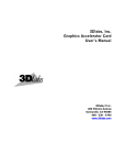
Directional Light
The directional light source is considered to be at an infinite distance from the subject, so that
the ‘rays’ of light can all be treated as being parallel. Therefore, the light source is specified
only as a direction vector. The closest real world analogy would be the sun illuminating an
object on the earth.
Light
The light source is defined in the Inventor (.iv) file as follows:
DirectionalLight {
direction 0 0 -1
}
The direction of the light source is specified by a vector, consisting of three values. These
represent the X, Y and Z components of the vector. In the example above, the direction is set
to the negative Z axis, which causes the light to point into the screen. This will cause the
scene to be evenly lit from the front.
The three components of the direction vector allow the light to be aimed in any direction you
wish. Preferably, the direction vector should have unit length. That is to say, the sum of the
squares of the three components should add up to one.
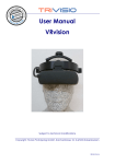
Point Light
The point light source emits light equally in all directions from a specific point. For example,
imagine a soft light bulb, floating in space. The exact position of the light can be specified.
13
Light
The light source is defined in the Inventor (.iv) file as follows:
PointLight {
location 0 0 1
}
The location (position) of the light source is specified again by a vector, consisting of three
values. These represent the X, Y and Z co-ordinates of the light source. In the example above,
the light is located at one unit on the Z axis. For our purposes, this places our light one metre
out from the centre of the screen. Increasing the X component (the first value) would move
the light to the right, and increasing the Y component (the second value) would move the light
up.
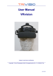
Spot Light
The spot light has a particular position in space, but also has a direction of illumination. For a
real world analogy, consider a desk lamp with a shade. This type of light projects light in a
particular ‘cone’.
Light
The light source is defined in the Inventor (.iv) file as follows:
SpotLight {
location 0 0 1
direction 0 0 -1
dropOffRate 0
cutOffAngle 0.785
}
The location (position) of the light source is specified again by a vector, consisting of three
values that represent the X, Y and Z co-ordinates of the light source (see PointLight).
The direction vector specifies which direction the light is aimed in (see Directional Light
above).
The cutOffAngle is the angle (in radians), measured from the direction vector, where the
cone of light will be cut off. This can be considered as the angle of the ‘lampshade’ in the
diagram above. In the example above, the angle is set to the default value of 45° (PI/4 ≈
0.785).
14
The dropOffRate is the rate at which the light intensity drops off (decreases) as the angle
between the ray of light and the direction vector increases. The value must be between 0
where the cone of light has equal intensity throughout, and 1 which specifies a narrow beam
of light.
Common Light Properties
There are some common properties that apply to all of the light types described above. These
allow the intensity and colour of the light to be adjusted, and allow a particular light to be
turned off and on.
The following example illustrates the default settings for the three common properties on a
directional light source. They are equally applicable to point and spot lights.
DirectionalLight {
on TRUE
intensity 1
color 1 1 1
}
The intensity value allows the brightness of the light source to be adjusted. The valid range is
from 0 (no light) to 1 (maximum brightness).
The color value specifies the colour of the light source in terms of three separate components:
red, green and blue. Each component ranges from 0 (minimum) to 1 (maximum). Some
typical colours are listed in the table below:
R
0
1
0
0
1
0
1
1
G
0
0
1
0
1
1
0
1
B
0
0
0
1
0
1
1
1
Colour
Black
Red
Green
Blue
Yellow
Cyan
Magenta
White
The light can be turned on and off by setting the on property to TRUE or FALSE
respectively. This feature is probably not very useful for this application.
Material Properties
The material properties of objects within the scene must be carefully considered to achieve
the desired appearance. For example, it is possible to achieve gloss or matte surface qualities,
to control object self illumination (glow / emissive lighting), and rudimentary transparency
effects.
In some cases, the material properties might already be contained within the scene file,
particularly when it has been exported from a 3D modelling package.
It is possible to specify custom material properties by adding the following text to a scene file
or modifier. However, bear in mind that your settings might later be overridden by settings
within the scene file itself.
15
Material {
ambientColor 0.1 0.1 0.1
diffuseColor 0.7 0.7 0.7
specularColor 0.3 0.3 0.3
emissiveColor 0 0 0
shininess 0
transparency 1
}
The ambientColor value is a simple colour value that simply adds to the apparent brightness
of the object, and does not consider the lights within the scene. It is specified as three values
in the range 0 to 1, representing the Red, Green and Blue components of the colour.
The diffuseColor determines the diffuse surface colour of the object when lit. It is specified
as three values in the range 0 to 1, representing the Red, Green and Blue components of the
colour.
The specularColor determines the specular colour when lit. It is specified as three values in
the range 0 to 1, representing the Red, Green and Blue components of the colour.
The emissiveColor determines the colour of the light emitted by the object. It can be used to
cause an object to appear to be self-illuminated, without external lighting. It is specified as
three values in the range 0 to 1, representing the Red, Green and Blue components of the
colour.
The shininess value controls the appearance of specular highlights on the object. It ranges
from 0 (which gives a dull, matte appearance), to 1 (which produces glossy looking surfaces).
The transparency value ranges from 0 (completely opaque), to 1 (completely transparent).
When completely transparent, the object will be invisible. Intermediate values will make the
object semi-transparent.
Multiple Light Sources
It is possible to specify multiple light sources within a scene file, and these can be of different
types. The number of supported lights, and the resultant performance, will vary significantly
from one machine to another (depending on the graphics card).
Base Colour Lighting
It is possible to apply a texture map to the scene that includes lighting and/or shadows,
perhaps from digital photographs, or pre-rendered material. In this case, it can be desirable to
use the texture map colour values directly, and to disable external light sources.
This can be achieved by inserting the following into the scene file:
LightModel {
model BASE_COLOR
}
When specifying this lighting model, there is no need to specify any additional light sources,
or to enable the headlight in the INI file, since the texture map colour will be used directly.
Instead of modifying the original scene file, it would be better practice to create a separate
modifier file, containing the light model settings. An example of a typical modifier file (called
‘unlit.iv’) is shown below:
16
#Inventor V2.1 ascii
LightModel {
model BASE_COLOR
}
From within Matlab, you can then specify the original scene file and the modifier as follows:
vrvis(‘SetFilename’, ‘YourScene.iv’)
vrvis(‘SetModifier’, ‘mod_unlit.iv’)
When the VRVision viewer is next started, the chosen modifier will be applied before loading
the scene file, so that lighting will be disabled. This technique makes it possible to apply any
number of different lighting conditions to the original scene file.
Animated Light Sources
It is possible to animate light sources by using the OpenInventor engines, such as the
ElapsedTime and Calculator nodes. For example:
1. Vary light intensity as a function of time.
2. Turn lights on and off in sequence.
3. Move lights along a predefined path.
6.2. The Scene Graph
Internally, VRVision builds an Open Inventor scene graph that describes the scene to be
displayed, and determines the order in which various transformations (such as rotation,
scaling and translation) are applied to the scene. This section illustrates the typical structure of
this scene graph, and how it is affected by various options given to VRVision.
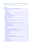
Default Scene Graph
The figure below shows the scene graph in the default state, without any options specified in
the INI file. Note that the X and Y rotation nodes are immediately before the Scene. This
means that any rotation (for example, using the SetAngleY function) will take place about the
origin of the scene itself. i.e. as it appears in the Inventor or VRML scene file.
Root Separator
Camera
Light
Translation
(scene pos)
Scale
Translation
X Rotation
Y Rotation
Scene
(auto centre)
You can select this behaviour by specifying the following options in the INI file before
starting VRVision:
[Scene]
RotateFirst=0
; this is the default
This is the default behaviour; if the RotateFirst option is not specified in the file, it is assumed
to be zero (disabled).
17
Rotate First Option
There is an option in the INI file that can be used to force the X and Y rotation nodes to be
inserted before the Translation (auto centre). This means that if both the auto centre and the
rotate first options are enabled in the INI file, the scene will be automatically repositioned at
the origin (based on the scene bounding box), and then rotated. The resulting scene graph is
shown below.
Root Separator
Camera
Light
Translation
X Rotation
Y Rotation
(scene pos)
Scale
Translation
Scene
(auto centre)
These options are very useful if the VRML or Inventor scene file has an origin that does not
lie near the centre of the object. You can select this behaviour by specifying the following
options in the INI file before starting VRVision.:
[Scene]
AutoCentre=1
RotateFirst=1
; enable automatic centre option
; rotate before translate
Note that this is only a small extract from the INI file. There are many more options detailed
in section 7.
6.3. The Open Inventor File Format
This section contains some background information about the Open Inventor file format, as
used by VRVision. This is too large a topic to cover in detail here, but after reading these few
examples, it should be possible to construct and edit some simple scenes and to have a basic
understanding of the structure and capabilities of Open Inventor files.
The Open Inventor 2.1 file format (Silicon Graphics Inc.) supports a plain text ASCII format,
as well as a binary format which is more compact and loads faster. This section will
concentrate on the plain text format, which makes it relatively easy to edit and create Open
Inventor files manually. It is also possible to create them automatically from within a Matlab
script, and an example of such a script (ivsurf.m) is provided on the VRVision web-site.
Although this section describes only the Open Inventor file format, it is worth mentioning that
the VRML file format is based on Open Inventor, and is therefore very similar. The Open
Inventor library (and VRVision) can load VRML1 files, but not VRML2 / VRML97 files.
This is a limitation of the open source version of Open Inventor 2.1. It future it would be
possible to recompile VRVision to work with the commercially available Open Inventor 3.1
or later, which is sold by Template Graphics Software (www.tgs.com), and which does
support VRML2. Alternatively, the Coin3D library from Systems in Motion also supports
VRML2. This is an Open Inventor work-alike, which is available under both open source and
commercial licenses.
Example 1: Creating a Cube
Open Inventor has built in support for a number of simple primitive objects, such as cubes,
cylinders, spheres and cones. We can create a file that contains one or more of these objects
very easily.
18
Start by using a text editor to create a new text file. Enter the text shown below, being careful
to copy it exactly as shown:
#Inventor V2.1 ascii
Cube {
}
Save this file as ‘cube.iv’. The .iv file extension indicates that this is an Open Inventor file, as
does the first line of the file. You may find that some text editors will not allow you to change
the file extension, and may automatically add the ‘.txt’ extension by default. If this happens, it
may be necessary to rename the file after saving.
When you have saved the file, you can try loading it into VRVision from the Matlab prompt
as shown below:
>> vrvis(‘SetFilename’, ‘cube.iv’)
>> vrvis
To ensure that the cube is visible, it is suggested that the automatic scaling feature is enabled
in the initialisation file. Otherwise, the SetScale command can be used from within Matlab to
adjust the scale.
In the example above, the first line is a special header that indicates that this is an Inventor
file, including a version number and that it uses the ASCII (plain text) format. All the
examples shown here will include this header.
The remainder of the file describes the scene graph. In this case, the scene graph consists of
just a single node, which is a cube. You will notice that after the name of the node ‘Cube’,
there is an open and closed curly bracket ‘{‘ and ‘}’. Every node has a number of fields,
which are usually parameters such as width, height, depth or radius. You can set these fields
to a particular value by listing the field names and values between the curly brackets.
For example, the cube node has width, height and depth fields. You can set them as shown
below:
#Inventor
Cube {
width
height
depth
}
V2.1 ascii
1
0.5
0.25
Try modifying the file with a text editor, so that you can see the effect of these fields. Note
that if you don’t set a particular field value, the default values will be used instead.
Example 2: Transformations
It is possible to move, rotate or scale objects within the scene graph. This is achieved by
inserting one or more transformation nodes. Some examples of transformation nodes are
listed below:
RotationXYZ
- rotate a node about the X,Y or Z axis
Scale
- change the scale of a node
Translation
- move an object (change the position)
You can apply multiple transformations to an node, for example to change both the scale and
position of an object. The transformations will be listed in the Inventor file in the order that
you wish to apply them. The node or object that you wish to transform should appear after the
transformation node(s).
19
For example, we can modify the ‘cube.iv’ file seen in example 1 so that the cube is rotated by
45 degrees about the Y axis. This involves adding a RotationXYZ node immediately before
the Cube node. However, the rotation angle is specified in radians rather than degrees, so we
must first convert our rotation angle into radians:
45 × PI / 180
0.785
The rotation node is then added to the file as follows:
#Inventor V2.1 ascii
RotationXYZ {
axis Y
angle 0.785
}
Cube {
}
Note how the rotation axis and angle are specified in the rotation node, and that the cube node
appears after the rotation node.
The scale and translation node are used in a similar way. The example below shows two
objects, one of which has a combined scale and translation applied:
#Inventor V2.1 ascii
Cube { }
Translation {
Translation 2 0 0
}
Scale {
scaleFactor 0.5 0.5 0.5
}
Cube { }
Note that the Scale node takes a vector of three values. These specify the scale factor on the
X,Y and Z axes respectively. Similarly, the Translation node takes a vector which specifies
how far to move the object on each of the X,Y and Z axes.
Example 3: Using Separators
There is a special node called the Separator which allows nodes to be grouped together in
such away that any transformations, materials or other attributes are only applied to that group
and will not affect other nodes in the scene graph. An example of this is shown below:
#Inventor V2.1 ascii
Separator {
RotationXYZ {
axis Y
angle 0.785
}
Cube { }
}
Cube { }
In the example above, we create a Separator node which contains a RotationXYZ node and a
Cube node. The rotation will be applied only to the first cube in the scene. The second cube is
not affected, since it lies outside the separator.
20
Example 4: Complex Surfaces
Here we provide a brief example of how more complex surfaces are represented within the
Inventor file. You would not normally edit the structures described here by hand, but this
information may be of use if you intend to write a script or program to generate such surfaces
automatically.
Complex surfaces are described with a mesh of interconnected triangles which define the
surface of the object. Usually, these take the form of a set of triangle strips. Each triangle
strip consists of one or more triangles, connected in a continuous strip, and defined by a
number of vertices (corner points). Within a strip, each triangle shares one edge (and two
vertices) with its immediate neighbour.
The vertices (points) and triangle strips are listed separately in the file. We start by listing the
X,Y,Z coordinates of each point, and then declare the triangle strip set. Within the triangle
strip set, we list the index number of each vertex. This is much easier to demonstrate with an
example:
#Inventor V2.1 ascii
Separator {
Coordinate3 {
point [
0 0 0,
1 0 0,
1 1 0
]
}
IndexedTriangleStripSet {
coordIndex [
0, 1, 2, -1
]
}
}
In the example shown above, the file begins with the Coordinate3 node, whose point field
lists the X,Y,Z coordinates of each triangle vertex. In this case, the vertices are located at
(0,0,0), at (1,0,0) and at (1,1,0).
The next node in the file is an IndexedTriangleStripSet, which defines a single triangle in
this case. Within this node, the coordIndex field defines one triangle strip, consisting of
vertices 0, 1 and 2. The end of the triangle strip is marked by the special value -1. Note that
the vertices are specified by a number which indicates their position within the vertex list,
starting from zero. This is more efficient, because a single vertex can be used within a number
of different triangle strips.
You will find more examples on the VRVision web-site, which include hundreds or thousands
of triangles described in the same way. There is also a downloadable script (ivsurf) which
generates surfaces of this type from within Matlab.
21
7. Initialisation File
There are many different preferences and settings that can be altered through the VRVision
initialisation file (also referred to as the INI file). This is simply a text file that can be edited
with most text editors. These settings are then loaded automatically when VRVision starts.
Therefore, if you make changes to the INI file, you will need to restart VRVision for them to
take effect.
The file is named:
vrvision.ini
It should be placed in the working directory of the VRVision plug-in. If the file cannot be
located, an appropriate error message is output to the Matlab window.
The format of the file is basically the same as the standard Windows INI file format. It
consists of a number of different sections, and each section contains one or more keys. For
example, the settings that describe the width and height of the display screen are described in
the INI file as follows:
[Screen]
Width=0.4
Height=0.3
In the example above, the section name is enclosed in square brackets [Screen], and the keys
are named Width and Height. This describes a display monitor with a width of 40cm and
height of 30cm (since the values are specified in metres).
Each key is associated with a different setting or preference and has a particular value, which
can be altered by the user. The names of the sections and keys are predefined and cannot be
altered. However, the values can be changed, and it is not necessary to include all the
supported keys. If a particular key is missing, the default setting will be used for that key.
If a section or key appears more than once, the last value to appear in the file will be used. We
do not recommend that you do this, because it is redundant, and because it will be confusing
for anyone reading the INI file later.
It is also possible to include comments in the INI file, which are useful to explain the meaning
of a particular key, and to document why a particular value is used for a given key. Comments
are denoted by using the semi-colon character at the start. For example, we might document
the screen settings with the make and model of the monitor so that a user will know which
monitor the INI file relates to:
[Screen]
; Iiyama Vision Master Pro 452
; This is the width and height of the display in metres
Width=0.365
Height=0.275
The remainder of this section lists the supported sections and keys, explains which values are
acceptable for each key, and what effect this has on the behaviour of VRVision.
7.1. [Screen]
The [Screen] section contains settings that describe the physical size of the display screen.
This should be the width and height of the visible image on the display surface in metres,
rather than the outer dimensions of the monitor.
The monitor should first be set to the chosen display mode and refresh frequency, since this
can affect the image size and proportions on screen. Any adjustments to the monitor settings
such as width, height, position should then be finalised. When a satisfactory image is
22
obtained, the image size can then be measured using a ruler. Please note also that the ratio of
the width and height specified here will determine the aspect ratio used for rendering.
The width and height are then specified in metre units, using the Width and Height keys:
[Screen]
Width=0.365
Height=0.275
In the example above, the displayed image is 365mm high and 275mm wide.
7.2. [Camera]
The camera settings control the position of a synthetic perspective camera, which represents
the viewer. This is the camera that will be used when a static view position is used. When
head-tracking is enabled, some of the camera parameters are modified automatically to
account for the head position of the viewer.
The following section lists each key in bold text, followed by a brief explanation.
EyeSeparation
This specifies the distance between the eyes, in metres. This setting is also termed IPD or
inter-pupillary distance. It is only used for stereoscopic 3D rendering, and has no effect on
monoscopic perspective display. When stereoscopic rendering is enabled, two separate views
are rendered by displacing the view position laterally from the camera centre position by half
the eye separation to the left and right of centre.
For example, we can specify an eye-separation of 65mm as follows:
EyeSeparation=0.065
NearDist
This is the distance to the near clipping plane. It defines the position of the front face of the
viewing frustum, nearest to the viewer. Any objects placed between the viewer and this plane
will not be visible, since they will be clipped. The near and far clipping planes will affect the
accuracy of the depth buffer (a mechanism in OpenGL which is used to determine whether
each pixel rendered is visible or occluded by another surface in the scene). The depth buffer
has a fixed resolution, which depends upon the graphics card and drivers. This resolution is
divided over the entire viewing frustum between the near and far clip planes. Therefore,
choosing clipping planes that tightly bound the scene will improve the depth buffer accuracy.
See also the FarDist key, which is used to set the distance to the far clipping plane.
An example to set up both clipping planes:
NearDist=0.1
FarDist=100.0
FarDist
This is the distance to the far clipping plane. It defines the position of the back face of the
viewing frustum, far from the viewer. Any objects placed beyond the far clipping plane will
not be visible, since they will be clipped. Please refer also to the NearDist key description for
more detail about the influence of clipping planes on depth buffer resolution.
Position
This specifies the initial position of the viewer when the scene is viewed from a static viewing
position. The position consists of three comma-separated values, specifying the X, Y and Z
coordinates of the viewer. For stereoscopic display, this defines the midpoint between the two
eyes. The origin is at the centre of the display surface. When facing the display, the X axis
points right, the Y axis points up and the Z axis points out of the screen towards the viewer.
23
For example, to place the viewer position in the dead centre of the screen, at 50cm distance,
the following settings would be used:
Position=0,0,0.5
Although the initial viewer position can be specified in the file, it is often overridden by
setting the view position from a Matlab script, or by using head-tracking.
View
This defines the viewing direction vector. It is a unit-length direction vector that controls the
direction in which the camera is aimed. Since the viewer will be facing towards the screen,
this is normally set to (0,0,-1) to indicate that the camera is aimed along the –Z axis. It should
not be necessary to alter this setting.
For example:
View=0,0,-1
Up
This defines the up direction vector. It is a unit-length direction vector that defines the up axis
of the camera. Since the +Y axis of the screen points up from the point of view of a user, the
up axis of the camera is also set to lie on the +Y axis. Therefore, this key is normally set to
(0,1,0). It should not be necessary to alter this setting.
For example:
Up=0,1,0
Final notes:
If you are familiar with the use of field of view angles and aspect ratio settings for setting
camera parameters, it is worth noting that in the case of VRVision, these are calculated on the
basis of the screen dimensions and view position relative to the screen. For example, the
aspect ratio is determined by dividing the screen width by the screen height.
7.3. [Tracker]
These settings are used to interface VRVision to an external tracking system, to support the
head tracking feature. VRVision talks to this external hardware through a proprietary library
called TrackLib. In order to connect to a particular device, TrackLib needs to know the device
name, the physical port that it is connected to (for example COM1 serial port), and which
tracked item is attached to the viewer or to the LCD shutter glasses. These settings are
provided by the [Tracker] section of the INI file.
The following section lists each key in bold text, followed by a brief explanation.
Device
This specifies the name of the tracking system that we wish to use for head-tracking. This is
passed directly to TrackLib, which searches for a match within the list of supported tracking
systems. If a tracking system is found (by a case insensitive, sub-string search), it attempts to
connect to that system. If the tracking system cannot be found, an error is displayed and the
tracking option is disabled.
Some examples are shown below, which denote the Polhemus Fastrak, the Logitech 3D
Mouse and the Vicon Real-time system respectively:
Device=fastrak
Device=3dmouse
Device=vicon
24
Port
This defines which port should be used to connect to the tracking system. It is a string of text,
prefixed with port: to denote a local connection, or net: to denote a network connection, and
followed by the specific port number or network address.
For example, a tracking system connected to a local serial port such as COM2 would have the
following INI file setting:
Port=port:2
For a system such as the Vicon Real-Time server, this would be the network address of
server. For example, if the server was running on a machine named nemesis, the following
port would be specified:
Port=net:nemesis
Finally, if you know that the device is connected locally but aren’t sure of the port number (or
if the device is frequently moved around), you can ask TrackLib to attempt to detect it
automatically:
Port=auto
GlassPort
Most tracking systems are able to track more than one item at any one time. For example, the
Polhemus Fastrak can have four separate receivers, each of which can be used to track one
object. It is therefore necessary to specify which of the available items is used to track the
head position of the viewer for head-tracking.
For example, if we have a pair of LCD shutter glasses fitted with a Fastrak receiver, and that
receiver is plugged into connector 1 on the front panel of the Fastrak, we would specify that
item 1 is used to track the glasses by adding this line to the [Tracker] section of the INI file:
GlassPort=1
7.4. [TrackerXForm]
When the tracking system reports the position of a tracked object to VRVision, it will almost
certainly use a different coordinate system to that of the display. For example, the tracking
system origin for the Polhemus Fastrak will be located at the centre of the magnetic
transmitter, not the centre of our display surface. Furthermore, the X, Y and Z axes will not
usually be aligned with those of the display.
For this reason, VRVision allows you to specify a transformation matrix, which defines how
to transform from the tracking system coordinate frame to that of the display. This is specified
in terms of the unit-length direction vectors of the X, Y and Z axes, and a position vector P
that defines the translation component.
For example, the settings below were used for a Vicon tracking system, where the tracking
system X axis was aimed towards the screen, the Y axis pointed left, and the Z axis pointed
up. The coordinate axes in VRVision are completely different, with the X axis pointing right,
the Y axis up, and the Z axis pointing out of the screen. The tracking system origin was also
located 1.2m vertically below screen centre at 3m distance. The transformation matrix given
below allows VRVision to transform between these two very different coordinate spaces:
[TrackerXForm]
X=0,0,-1
; ViconX =
Y=-1,0,0
; ViconY =
Z=0,1,0
; ViconZ =
P=0,-1.2,3 ; -1.2m on
-ScreenZ
-ScreenX
+ScreenY
Y axis, 3m on Z axis
If the tracking system axes happen to match those of VRVision, and only a simple position
offset is required, the X, Y and Z vectors would be specified as shown below:
25
X=1,0,0
Y=0,1,0
Z=0,0,1
Then the P value can be used to specify the X, Y and Z position offset.
7.5. [GlassesXForm]
If a tracking receiver or target is attached to a pair of LCD shutter glasses, or perhaps to a
headband, it can be used to track the position of the viewer. However, the tracking system
will report the position and orientation of the object being tracked, whereas VRVision
requires the position and orientation of a synthetic camera located at the midpoint between the
eyes of the viewer. The [GlassesXForm] section allows you to specify the transformation
from the tracked object to the midpoint between the eyes.
As with the [TrackerXForm], the transformation matrix is specified in terms of three unit
length direction vectors of the X, Y and Z axes, and a position vector P.
For example, when the Vicon system reports the location of the glasses, the +X axis is aligned
with the viewing direction, the +Y axis points left and the +Z axis points up. However, our
synthetic camera is arranged so that the viewing direction is along the –Z axis towards the
screen, the up vector is the +Y axis and the +X vector points to the right. For this example,
the origin of the object was located at the midpoint of the eyes, so that no position offset is
needed.
We can specify a transformation between these two coordinate systems as follows:
[GlassesXForm]
X=0,-1,0
Y=0,0,1
Z=-1,0,0
P=0,0,0
;
;
;
;
CameraX = -ViconY
CameraY = ViconZ
CameraZ = -ViconX
No position offset needed in this case
7.6. [Scene]
This section contains various settings that determine which scene file is loaded by default, and
how it will be displayed within VRVision. For example, it is possible to enable a default light
source, to scale the scene and to automatically centre the scene at the origin.
The following section lists each key in bold text, followed by a brief explanation.
File
This specifies the name of the scene file to load by default. It can be any suitable
OpenInventor 2.1 or VRML 1.0 format file. When VRVision is started from within Matlab
without any parameters, this is the file that will be loaded.
For example:
File=scene.iv
Headlight
This option can be used to enable a simple directional light source, aimed along the –Z axis
into the scene. If you wish to specify your own light sources within the scene file, it is
recommended that you disable this headlight.
For example:
Headlight=1 ; enable the light
Headlight=0 ; disable the light
26
Scale
This specifies the scale of the scene for display purposes. If the object size is carefully
defined, and the scale and screen size are specified correctly in the INI file, it is possible to
display an object at actual size.
For example, if the screen size is 40cm by 30cm, and our scene file contains a 20cm cube,
then the scale can be set to 1 to display that object on screen at actual size:
Scale=1
However, if scale is not important and you want the object automatically scaled to fit on the
screen, you can set the scaling mode to automatic:
Scale=auto
The scale factor is also commonly used to scale between units such as imperial and metric, or
to scale an object relative to the original size in the scene file, for example:
Scale=0.5
AutoCentre
If an object described in a scene file is to appear at the centre of the screen, it should be
located at the origin (0,0,0), since the origin in VRVision is located at screen centre.
However, not all scene files will necessarily be defined to lie at the origin. The AutoCentre
option can be used to automatically move the scene to the origin when it is loaded. This works
by calculating the centre of the bounding box of the scene (the smallest axis aligned box that
completely encloses the scene), and translating or moving the scene by that amount so that it
is relocated at the origin.
For example:
AutoCentre=0
AutoCentre=1
; don’t move the scene
; move the scene to the origin
Note that the scene will also rotate around the origin when using joystick or mouse movement
functions. This option can then affect whether an object will rotate about the origin of the
object, or the centre of the bounding box. Also refer to the RotateFirst option.
RotateFirst
This option forces the X and Y rotation nodes to be inserted before the Translation node that
is used to implement the auto-centre feature. This means that if both the AutoCentre and
RotateFirst options are enabled, the scene will be automatically repositioned at the origin and
then rotated. This is explained in more detail in section 6.2.
For example:
RotateFirst=0
; rotate after translation
RotateFirst=1
; rotate before translation
UnderlayBlit
VRVision is able to automatically capture the contents of the screen before it starts (see the
UseUnderlay function for more information), and to display this as a textured background
behind the objects that it renders. VRVision implements two different methods to achieve
this, since the performance and quality of each may vary from one graphics card to another.
This INI file option selects which implementation is used:
UnderlayBlit=0
UnderlayBlit=1
; Use texture mapping method
; Use blit / block-transfer method
If a particular method does not perform well on your chosen graphics card, you can try
changing this option to see if it improves the speed or quality.
27
ForceTopMost
If enabled, this option causes VRVision to force itself on top of all other windows on the
desktop. On the Windows operating system, it does this by applying the top-most window
property. If this option is disabled, VRVision will still raise itself above other windows, but in
a less forceful way (which is the default).
ForceTopMost=0
ForceTopMost=1
; raise window to top politely
; force window on top
ForceStereoPF
When using stereoscopic display in OpenGL, VRVision automatically creates a window with
a stereo pixel format. If the ForceStereoPF option is enabled, this will cause VRVision to
always use a stereo pixel format, regardless of whether the stereoscopic display is enabled.
For example, in an experiment this will ensure that the LCD shutter glasses are enabled (i.e.
flickering) even when displaying monoscopic images. This means that an experimental
participant can wear the glasses in both monoscopic and stereoscopic conditions, and will
therefore experience similar flicker and display brightness in both cases.
ForceStereoPF=0
ForceStereoPF=1
; use stereo only in stereoscopic mode
; always use stereo, even for monoscopic
Note that there is a performance cost associated with the use of a stereoscopic pixel format,
since it is necessary to render the scene twice, once for the left eye and once for the right eye.
Therefore, this option is only recommended for special cases such as the example described
above.
ShowCursor
This option determines whether the mouse cursor is visible when VRVision runs in fullscreen
mode. The mouse cursor is hidden by default.
ShowCursor=0
ShowCursor=1
; hide mouse cursor (default)
; show the mouse cursor
ShowHud
This option can be used to turn the ‘head up display’ on and off, which displays statistics
about the rendering performance. Currently, this is limited to a simple display of the frame
rate, indicating the number of frames per second that can be achieved for a particular scene.
You will normally want to leave this option disabled, but it can be useful to know the current
frame rate when setting up an experiment, or to see what effect a particular feature (such as
stereo or anti-aliasing) has on performance.
ShowHud=0
ShowHud=1
; hide head up display
; show head up display
IVCacheMin
This is used with a customised version of the OpenInventor graphics library to set the
IV_AUTO_CACHE_MIN environment variable. This affects the caching policy of
OpenInventor, and can improve performance in some cases by allowing it to cache complex
scenes by constructing an internal display list for more efficient rendering.
For example:
IVCacheMin=1000
; alter OpenInventor cache limit
CaptureMouse
This option determines whether VRVision uses mouse capture within Windows to capture
mouse messages:
CaptureMouse=0 ; don’t capture mouse (default)
CaptureMouse=1 ; capture mouse input
28
7.7. [Joystick]
This section contains settings that affect the behaviour of the joystick or game controller.
These settings influence the sensitivity of the joystick when it is used to manipulate objects.
The following section lists each key in bold text, followed by a brief explanation.
Deadzone
Most joysticks are sprung so that the stick will return to a zero or centre position when
released. However, they do not always return exactly to centre, and may report a small nonzero position value even when the user is not applying any pressure to the stick. The
Deadzone parameter allows you to specify a lower limit value, below which the joystick
movement will be ignored. Increasing the Deadzone value means that the user will have to
push the joystick further from centre before the scene will begin to move.
The acceptable range of the Deadzone value is between 0 and 1, but is typically a very small
percentage of this range such as 0.1. This is because the full scale for the joystick movement
is in the range -1 to +1. Therefore, a Deadzone value of 1 would disable the joystick
completely.
For example:
Deadzone=0.1
Some joysticks already implement this method at a driver level, in which case a Deadzone
value of zero can be specified to disable this feature in VRVision.
Scale
The scale parameter allows the sensitivity of the joystick to be adjusted. Increasing the scale
will cause the scene to move faster in response to the same amount of stick movement. After
clamping the joystick values within the Deadzone limits described previously, they are
multiplied by the Scale parameter to determine the rate of scene movement.
Therefore, reducing the scale will make the stick less responsive, and increasing it will make
the stick more responsive. Some joysticks may offer similar parameters within the control
panel and device settings.
For example:
Scale=0.1
29
8. Hardware for Stereoscopy
This section outlines some of the hardware requirements, if you wish to use the stereoscopic
feature within VRVision. Stereo support has improved considerably on graphics cards, but
can still be problematic in some cases. However, with the right choice of equipment, it is
possible to achieve a good quality stereoscopic display on relatively inexpensive PC based
commodity hardware.
8.1. Display Devices
There are many possible methods for displaying stereoscopic imagery, some of which are
listed here briefly:
1. CRT monitor, with LCD shutter glasses.
2. Stereo capable CRT video projector, with LCD shutter glasses.
3. Stereo capable DLP video projector, with LCD shutter glasses.
4. Pair of LCD/DLP projectors with polarising windows, and polarised glasses.
5. CRT/LCD/DLP with “Z-Screen” polarizer, and polarised glasses.
6. CRT/LCD/Plasma monitor with surface mounted lens array.
7. CRT/LCD/Plasma monitor with grating (‘Barrier’ stereo method).
This list is by no means comprehensive, and the range of commercially available stereo
display systems continues to expand. However, arguably the most commonly used display
system for stereoscopy on the desktop is the combination of LCD shutter glasses and a CRT
monitor. This is the solution that we will describe here, along with some examples of suitable
glasses and display monitors.
Many of the techniques described above will function with VRVision, providing that the
device in question is compatible with the OpenGL quad-buffer stereo format. However, there
are some displays (certain of the new free viewing flat panels for example), that will not be
directly compatible.
Shutter Glasses
There are several different varieties of LCD shutter glasses available, and a comprehensive
review is not possible here. However, two suitable models that are worth considering are the
CrystalEyes (StereoGraphics Corp.), and the nuVision 60GX (MacNaughton Inc.). These both
have reasonably large LCD panels (so as not to restrict the field of view of the user), are
relatively comfortable to wear, and have good compatibility with most workstation graphics
cards that have stereo support.
When buying glasses, it is important to check for compatibility with the graphics card in
question. The preferred interface is the 3-pin VESA stereo DIN connector. This is simply a
miniature 3-pin DIN socket, which provides power to the glasses, and a synchronisation
signal to switch the LCD panels at the appropriate moment. If you have a graphics card that
does not offer the 3-pin VESA stereo connector, then you will need an external interface of
some kind to derive the synchronisation signal from the VGA connector. For example, the
StereoEnabler (StereoGraphics Corp.), and the nuVision 60GX-NSR emitter (MacNaughton
Inc.) both connect to the VGA port of a graphics card. You will need to check that your
graphics card and drivers are compatible with these devices before buying.
30
Technical information on the glasses, and compatibility issues, is available from the following
sources:
http://www.stereographics.com
(CrystalEyes glasses)
http://www.nuvision3d.com
(nuVision glasses)
http://www.stereo3d.net
(reviews, information)
http://www.stereovision.net
(forum, links, news)
Monitors
The shutter glasses function by alternately blocking the left and right eye using liquid crystal
shutter panels, in synchronisation with the display. The left and right eye images are displayed
alternately, so that each eye will receive a different image, resulting in a stereo effect.
For this to work, the image must ‘persist’ on the display for a very short time, which in
practice means that only CRT monitors are suitable. Unfortunately, LCD flat panel monitor
and plasma displays are currently too slow to be compatible with shutter glasses. If the image
persists for too long, there will be no stereo effect, or at least a very severe ‘ghost’ image (this
term means that the left eye image can be partially seen on the right eye, and vice versa).
Therefore, you should select a good quality CRT monitor, preferably one with a short
persistence phosphor.
The second problem is that the vertical refresh frequency of the monitor is effectively halved,
so that flicker might be perceived by the user. This can be avoided by increasing the vertical
refresh frequency of the monitor. However, the maximum frequency available will depend
upon the display resolution. For example, a monitor may support 100Hz refresh at 1024×768,
but only 75Hz at 1280×1024. Therefore, you will need to decide what resolution and refresh
rate you need before selecting a monitor.
Increasing the vertical refresh rate will decrease the flicker. The maximum vertical refresh
rate is usually limited by the monitor, rather than the graphics card. You should aim to have a
vertical refresh rate of at least 100Hz, preferably 120Hz if possible. Also, it is not
recommended to drive a monitor outside the limits recommended by the manufacturer, since
this can result in permanent damage.
Finally, you will see a reduction in brightness when viewing stereo images when compared to
mono images. This is due to the attenuation of the LCD shutter (which does not become
perfectly transparent when open), and since each eye will be exposed to the image for only
50% of the time (the LCD shutter is opaque for the remaining time). In an experimental study
that compares mono and stereo viewing, this will need to be considered.
8.2. Graphics Cards
This section describes some of the graphics cards that are suitable for use with VRVision, and
attempts to address some of the technical issues involved in using these cards. Please note that
the graphics industry moves very quickly; it is likely that the cards described here will soon
be replaced by a new generation.
The general requirements are as follows:
1. Must support hardware accelerated OpenGL 1.2 or above.
2. Must support “quad-buffer OpenGL stereo”, that is to say: it must be possible to
create an OpenGL window with a stereo pixel format. In general, these tend to be
classed as “workstation” graphics cards.
3. The graphics card must be compatible with your choice of stereoscopic display
hardware. For example, if your LCD shutter glasses have a 3-pin VESA stereo
31
connector, then you must use a graphics card that features this connector (or you must
use an external adaptor).
When selecting a graphics card, be aware that many consumer class graphics cards support a
specific type of stereo 3D that is designed for use in games. This does not necessarily mean
that these cards support true quad-buffer stereo in OpenGL, which is required for VRVision.
At time of writing, there is an excellent summary of compatible 3D hardware available on the
StereoGraphics web-site:
http://www.stereographics.com/support/boards/brd-chrt.htm
The 3DLabs Wildcat family
The 3Dlabs Wildcat 3 (6110/6210) and Wildcat 4 (7110/7210) are workstation class graphics
cards that offer accelerated OpenGL support, and feature a 3-pin VESA stereo connector.
These cards are directly compatible with most stereo shutter glasses, such as CrystalEyes
(StereoGraphics Corp.) and nuVision 60GX (MacNaughton Inc.). However, they are
relatively expensive, workstation class graphics cards.
For detailed specifications and reseller information, please visit the manufacturer web-site:
http://www.3dlabs.com
In order to use stereo support on these cards, you must select a “Frame Sequential Stereo”
display mode using the Display Settings dialog.
The nVidia Quadro/GeForce family
The nVidia Quadro family is targeted at professional workstation market, and offers excellent
OpenGL performance and stereo support at a competitive price. The nVidia GeForce is based
on the same chip set, but targeted at the consumer market, and lacks some of the features of
the professional card (such as quad-buffer stereo support). In both cases, driver support is
excellent, with a good OpenGL implementation. The Quadro cards are available with 3-pin
VESA stereo connectors, making them compatible with most stereo shutter glasses, including
CrystalEyes (StereoGraphics Corp.) and nuVision 60GX (macNaughton Inc.).
For cards that do not feature the 3-pin VESA stereo connector, it is still possible to connect
stereo shutter glasses by using an external interface box such as the StereoEnabler
(StereoGraphics Corp.), which attaches to the VGA connector of the graphics card and
converts this to a 3-pin VESA output. This is only possible if the graphics driver is able to
place the appropriate stereo synchronisation signal on the VGA port, for example the “blue
line code” that is used by StereoGraphics products.
There is more information available on the StereoGraphics web-site:
http://www.stereographics.com
When installing the card, you have the choice of either installing the drivers that came with
the card, or downloading the latest drivers from the manufacturer. In our experience, the best
option is to download the latest nVidia Detonator drivers from the nVidia web-site:
http://www.nvidia.com
Having installed the drivers, you will find that quad-buffer stereo is disabled by default. In
order to use stereo, you must enable the option in the display settings dialog. There follows an
example of how to configure an nVidia Quadro card to enable stereo under Windows 2000.
First, open the display properties dialog (Figure 1), either by right clicking on the desktop and
selecting Properties, or by opening the control panel and double-clicking on Display.
32
Figure 1. Display Properties Dialog
In the display properties dialog (Figure 1), click on the Advanced… button, to open the
advanced properties dialog (Figure 2).
You should click on the tab that lists the name of your graphics card, which in this example is
a Quadro2 MXR/EX. Under Display Adapter Information (see Figure 2) you should see your
Graphics Processor identified as a Quadro (if not, then you are unlikely to have stereo
support).
Figure 2. Advanced Properties Dialog
Click on the Additional Properties… button to proceed, and you should then see the
additional properties dialog (Figure 3). You will need to click on the tab for OpenGL settings,
to see the options shown below.
33
Figure 3. Additional OpenGL Properties
At this point, you should make sure that ‘quadbuffered stereo API’ is enabled, and ‘overlays’
are disabled. Your settings should match those shown in the upper white box in Figure 3.
Having made these changes, you should be able to run VRVision in stereo. Note that it may
be necessary to restart Matlab and VRVision before the changes take effect.
While you are in the Display Properties dialog, you should change the vertical refresh
frequency to the maximum that your monitor can safely support for the current display mode.
This is changed using the Monitor tab as shown in Figure 4. Please check which modes are
supported by your monitor before changing this setting and test the display mode before
applying changes.
Figure 4. Monitor Vertical Refresh Frequency
34
9. Tracking Systems
VRVision supports head tracking, if a suitable tracking system is available, and has been
properly configured. This feature can be enabled and disabled as required by the
UseHeadTrack function.
When head tracking is enabled, the tracking system is used to measure the position of the
shutter glasses, and the approximate position of the left and right eyes is calculated from this.
The display is dynamically updated to provide an appropriate projection, based on the head
position of the viewer. This feature is available in both monoscopic and stereoscopic display
modes. When disabled, the fixed viewing position is used (this is read from the INI file by
default, and can be overridden by the SetViewPos function from Matlab).
When using a tracking system, most of the configuration settings are read from the INI file,
since they are not usually changed during the course of an experiment. These settings include
information about which communication port the tracker is connected to, and calibration
settings that account for the placement of the tracker relative to the screen and the glasses.
9.1. Supported Tracking Systems
At present, the following tracking systems are supported:
1.
2.
3.
4.
Ascension Flock of Birds (electromagnetic)
Vicon Real Time Server
Polhemus Fastrak (electromagnetic)
Logitech 3DMouse (ultrasonic)
We have access to all the systems listed above, and are prepared to support them. If problems
are reported with any of the systems above, and can be reproduced locally, then we will try
and provide a solution. This is done as a courtesy, and does not constitute a guarantee.
The following systems are partially supported, or unsupported. That is to say, they have either
not been extensively tested with VRVision, or they are still under development. In some
cases, we do not have access to the system, so continued development and testing is not
possible.
1.
2.
3.
4.
Image Guided Technologies, Flashpoint 5000 (optical)
Northern Digital, Polaris
Qualisys Track Manager Real Time
Intersense (various)
9.2. Configuration File Settings
There are three separate sections in the INI file that are used to configure the tracking system
for use with VRVision:
[Tracker]
; tracker/communication settings
[TrackerXForm] ; transform: transmitter/screen
[GlassesXForm] ; transform: receiver/glasses
These are documented in section 7, and briefly summarised here.
Sample: Logitech 3D Mouse
Here is a complete sample configuration for Logitech 3D Mouse on COM1. Note that the rest
of the INI file has been omitted for reasons of space, and only the three sections that relate to
the tracking system are shown here:
[Tracker]
Device=3dmouse
; name of tracking system to use
35
Port=port:1
GlassPort=1
[TrackerXForm]
X=1,0,0
Y=0,1,0
Z=0,0,1
P=0,0.466,0.295
[GlassesXForm]
X=1,0,0
Y=0,-0.89879,-0.43837
Z=0,0.43837,-0.89879
P=0,-0.08,0.04
; which COM port to use (or ‘auto’)
; which port the glasses are on
; direction vectors for transmitter
; translation for transmitter
; direction vectors for receiver
; translation for receiver
The TrackerXForm specifies the transformation between the tracking system transmitter and
the screen centre. In this case, the transmitter was mounted centrally on top of a 19” flat
screen monitor, and the axes were aligned with the monitor. Therefore, only a position offset
(translation) is needed in the example above.
The GlassesXForm specifies the transformation between the tracking system receiver, and a
point that lies halfway between the two eyes of the viewer. In this case, the receiver was
mounted on the top of a pair of CrystalEyes glasses, facing towards the transmitter, and tilted
backwards towards the forehead. Therefore, the direction vectors are used to account for this
rotation on the X axis. Since it is a simple X axis rotation, you will notice that the X direction
vector is unaffected in the example above. As with the transmitter, a position offset is also
needed.
Sample: Ascension Flock of Birds
Here is a complete sample configuration for an Ascension Flock of Birds (with a single
receiver) on COM1. Note that the rest of the INI file has been omitted for reasons of space,
and only the three sections that relate to the tracking system are shown here:
[Tracker]
Device=bird
Port=port:1
GlassPort=1
[TrackerXForm]
X=-1,0,0
Y=0,0,-1
Z=0,-1,0
P=0.51,-0.27,0.38
[GlassesXForm]
X=0,0,-1
Y=0,-1,0
Z=-1,0,0
P=0,0,0.07
; name of tracking system to use
; which COM port to use
; which port the glasses are on
; direction vectors for transmitter
; translation for transmitter
; direction vectors for receiver
; translation for receiver
The [TrackerXForm] specifies the transformation between the tracking system transmitter and
the screen centre. In this case, the tracker (X,Y,Z) axes were aligned with the screen (-X,-Z,Y) axes respectively. Therefore, the X axis vector in the [TrackerXForm] is set to the –X axis
(-1,0,0), the Y axis vector is set to the –Z axis (0,0,-1) and the Z axis vector is set to the –Y
axis (0,-1,0).
The position offset P in the [TrackerXForm] accounts for the position of the transmitter
relative to screen centre. In this case, the transmitter origin was located 51cm right of the
screen centre, 38cm in front of the screen plane, and 27cm below the screen centre.
36
The GlassesXForm specifies the transformation between the tracking system receiver, and a
point that lies halfway between the two eyes of the viewer. In this case, the receiver was
mounted on the right arm of a pair of CrystalEyes glasses, facing towards the monitor, with
the base of the receiver mounted flush against the outside of the arm of the glasses. The
receiver cable was taped to the end of the arm, just above the ear.
The viewing direction of the user was assumed to be along the X axis of the receiver, but the
camera in our scene looks along the –Z axis. Therefore, the X vector in the [GlassesXForm] is
set to point along –Z axis (0,0,-1). Similarly, the up vector of the camera is on the +Y axis,
whereas the up axis of our receiver is –Y. Therefore the Y vector in the [GlassesXForm] is set
to the –Y axis (0,-1,0). Finally, the Z axis of our receiver points along the –X axis, so the Z
vector is set to the –X axis (-1,0,0).
It’s important that these three vectors form an orthogonal, right-handed coordinate frame.
There is a position offset of 7cm to account for the fact that the receiver is placed some
distance to the right of the eye centre.
37