1
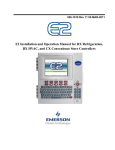
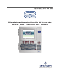
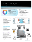
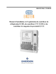
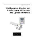
3.3.2
CC-100 Case Controller and
CS-100 Case Circuit Controller
Generally, the case controller will be mounted within
the raceway or on top of the case. If a controller must be
replaced or installed in the field, it should be located based
on the specific design of the case.
10.00"
4.75"
TYP 2 PL
O 0.220"
TYP 6 PL
4.00"
SmartESR BOARD
3.50"
WEIGHT 9.4 OZ.
8.05"
O 0.18“
TYP 2 PLACES
O 0.25"
TYP 2 PLACES
2.25"
0.25"
2.00"
CONTROLLER
(TOP VIEW)
CONTROLLER
(SIDE VIEW)
26502032
Figure 3-13 - CCB Mounting Dimensions
3.3.3
9.50"
ESR8 (Discontinued)
The ESR8 board is slightly larger than the 16AI and
8RO boards, and is not supplied with a snap-track. If the
ESR8 is supplied without an enclosure, it is supplied with
0.500” long metal stand-off dowels which are pressed into
the mounting holes in the board (See Figure 3-14).
26501055
Figure 3-15 - Mounting Dimensions for the SmartESR
3.3.5
0.25"
0.50"
3.00"
0.50"
8.95"
TD3
The TD3 temperature display is almost always
mounted by the OEM as part of the construction of the
refrigerated cases. As such, field installations of TD3s are
rare.
TD3s are typically flush mounted on the front of a
refrigerated case in such a way as to be fully visible from
the sales floor. A hole one inch in diameter must be drilled
into the case to allow the TD3’s wiring harness to extend
into the case and connect to the network, the power source,
and the case-mounted probes. Figure 3-16 shows the
mounting dimensions of the TD3.
Figure 3-16 - TD3 Mounting Dimensions
Figure 3-14 - Mounting Dimensions for the ESR8
3.3.4
SmartESR
The SmartESR is supplied with a snap-track. If the
ESR8 is supplied without an enclosure, it is supplied with
0.500” long metal stand-off dowels that are pressed into
the mounting holes in the board.
3.4 Modem/Communication Expansion Card Mounting (New Processor Board)
The E2’s modem/communication expansion card
mounts above the PIB in the back of the enclosure box as
shown in Figure 3-17. The standoffs and mounting holes
are located above the PIB in the back of the enclosure box.
Use the mounting screws and standoffs to secure the card
in place. For more information on the modem/communication expansion card, see Section 4.3.2, Modem/Communication Expansion Card (New Processor Board).
Modem/Communication Expansion Card Mounting (New Processor Board)
Mounting • 3-5