1
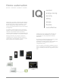
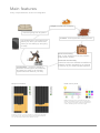
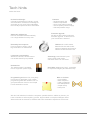
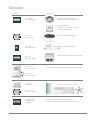
Integra IQ@Home
user manual v1.2
www.cybrotech.co.uk
Home automation
sensors - controllers - actuators - interface
IQ
Integra IQ is a system of devices and software
mainly targeted for home automation. Primary
function is control of home equipment - lights,
blinds, heating and cooling; but it can also
cover more sophisticated functions, like energy
management.
It consists of simple autonomous units which
together create a complex and unique system.
Units are connected to each other with a
common power supply and communication bus.
Units may be combined in many different ways.
Although basically very simple, expansion
capabilities are virtually unlimited. System is
configurable, programmable, and two or more
basic systems can integrate together.
comfort
energy saving
security
safety
simple
flexibile
cost-effective
Integra IQ can be used equally well both for
new projects and adaptations. For a basic
functionality, the only specialist needed is
electrician.
No expert is needed for project (generic project
can be used for most installations),
programming (basic functions are available out
of the box), or configuration (system is
configured by user).
User can select units without assistance, there
are no complicated compatibility or dependency
rules. Use what you like now, upgrade any time
later.
1
Main features
many unique features, accent on integration
simple to install and configure
control anything from anywhere
scalable - build system like stacking bricks
use smartphone to let system know
about you, when you are at home,
when you are waking up and going
to sleep
basic functionality
plug ‘n’ play, works out of the box, without
expert action needed
configurable - you are in charge to
determine what happens automatically,
and what you prefer to do manually,
system will never stand in your way
Multiple timetables
advanced functionality
custom functions are available as additional
software modules, prepared by our experts
to meet up to your most exquisite requests
RGB control panel
RGB mode allows control of brightness and color,
instead of individual channels. In color temperature
mode, output goes between different temperatures
of white, matching interior and exterior light.
Set things running up to your schedule. To configure the timetable,
select active hours, then select devices which should be affected.
You can manually override device state at any time.
2
Scene editor
Scene is user-defined memory including
lights, dimmers and blinds. Each output is
either defined by scene (on/off, lightness
and position), or not affected.
Each scene controller comes with a four
programmable scenes. Scene may be
defined by controller (long press), or by
mini scada (scene editor).
Scene matrix
Use an input to set a scene.
Especially useful in a large rooms, where
lights can be always at your fingetips.
Light matrix
Light matrix provide user-defined connection
between inputs and outputs. Light on means
input will turn the selected output on and off.
Light off means the output will be turned off,
each time the input is activated. Blinds are
not affected.
Column can also be activated by an event,
hugely extending the number of available
combinations. Column can be used, even
when associated controller is not connected.
Light matrix is a perfect solution for secondary
lights, such as hallway, porch, garden, garage
and others.
3
Automation
Warm wake up
Wake up into a warm house.
System will turn heating on a
predefined number of minutes
before the smartphone alarm
rings, whenever you set the
alarm.
Call notification
When you receive a call,
selected light will turn on and
off couple of times, to bring
attention when phone is away
or silenced.
Sunny wake up
Wake up naturally, by slowly
lifting bedroom blinds and
letting the sun does its
bussiness a few minutes before
the alarm clock rings.
Text notification
When you receive a text
message, selected light will turn
on and off couple of times, to
bring attention when phone is
away or silenced.
Coming home
Let your house show how
happy it is when you get home!
When phone detect home wi-fi
network, it turns the heating on,
and optionally lights.
Smart lights
In the evening hours, when
sunlight goes down,
automatically set evening
scene, turn on the lights and
lower blinds. Works only when
tenants are at home.
Leaving home
When you leave the house, a
few minutes after phone
disconnects from home wi-fi
network, system will turn the
heating off, and also the lights.
Random lights
When nobody is at home,
prevent burglary by a simple
deception: turn lights on and off
to leave impression that house
is not empty.
Connect charger
Charge your phone every day
at the evening, in moment
when you are already in bed?
Use that action to also turn
heating and lights off.
Bio offset
Following your natural
biological rhythm (chronotype),
let the house be just a little
warmer at the specified time of
the day, morning or evening...
or both.
Disconnect charger
Disconnect charger every
morning, just before you get out
of the bed? Use that action to
automatically turn heating and
lights on, but only if sunlight is
still low.
Eco mode
Manual setpoint adjustment will
be valid for about one hour,
then it will slowly return to the
predefined, more optimal value.
The most frequently used function of a home automation is - how to turn the damn thing off.
However, regardless the infamous attitude towards smart machines, we strongly believe
Integra will gradually grow up into your daily routine. Events are based on your smartphone,
all the chances are that you already have one in your pocket. You are in charge to pick events
and assign actions up to your preferences. Give it a chance, you won’t be dissapointed.
4
Tech hints
under the hood
Professional design
Cybrotech originate from industry control
and automation, all devices are designed
and build up to a much higher standards
then usually expected in home automation.
Automatic addressing
Devices are addressed automatically,
not a single address is set by user.
Extremely fast response
From keypress to action, typical
lag is less then 10 milliseconds.
Low power consumption
Whenever relevant, we take care to
use as little electricity as possible.
No batteries
The whole system is operated
from a single 24V power supply.
Programming tools are free, everybody
is welcome to participate. Only a basic
programming skills are needed. Join our
group and discover how fun and simple
house automation can be.
Features
- hardware watch-dog
- transient supression
- short circuit tolerant outputs
- reverse polarity tolerant supply
- wide temperature range
Firmware upgrade
All devices are build to implement
firmware upgrade, so the future for
your investment is assured.
CAN bus is a multi-master,
deterministic bus which offer
optimum between performance,
network architecture and cost.
Autorange potentiometer inputs
ensure a full scale motion,
whichever device is connected.
No hidden costs at any level - everything
is simple and elegant (and beautiful, too).
Wire or wireless:
- more reliable
- faster response
- need no batteries
- less EMI pollution
- simpler setup
- lower price
We don’t sell switches, luminaries, computers, portable devices, tablets or phones; you
have a freedom to select anything you like, buget models or overpriced designer items.
What we do sell is electronics, software and home automation experience at it’s finest.
5
System upscale
project-based features
Internet
access
access
control
security
safety
energy
management
appliance
control
smart grid
integration
surveillance
audio/video
system
DIY devices
KNX
bridge
LON
bridge
X10
bridge
Zigbee
bridge
BMS
integration
project-based
features
interconnection between basic IQ systems
out of the box
features
Integra IQ offer many out-of-the-box functions. However, modern home automation is all
about integration, and that is where the IQ excels. Integra, as the name says, tend to be
the network capable of connecting various devices into a functional system. Integration
is project-based, each home is carefully attuned to investor and building requirements.
Basic IQ system
tablet
230VAC
smartphone
laptop
Wi-Fi
Ethernet
router
Ethernet
IEX bus
switchboard
desktop PC
6
Devices
Device
Used for
LC-10-IQ
light controller
LC-10-IQ
light controller with 10 relay outputs
led and halogen downlighters
all kinds of general-purpose lights
managed sockets
floor lamp, hi-fi system, projector
all kinds of appliances
LC-V4-IQ
LED constant voltage 4 channel dimmer with RGB mode
LC-D8-IQ
DALI master controller
BC-5-IQ
blinds controller for 5 blinds
LD-V4-IQ
LED dimmer
LED stripes, white and RGB
LD-D8-IQ
DALI controller
all kinds of dimmable lights
BC-5-IQ
blinds controller
window blinds, shutters and jalousies
SC-4O-IQ
scene controller
user-programmable arrangement of lights and blinds
SC-4S-IQ
scene controller
TH-1-IQ
thermostat
FC-1-IQ
fan-coil or radiator/fan controller
heating, cooling and fan control
FC-1-IQ
fan-coil controller
CyBro-2-IQ
programmable
controller
smartphone and mini scada connection
automation, timetable and many other functions
7
Software
CyBro IQ Commander
- for Android phone or tablet
- control lights, blinds and
thermostats
- presence and alarm events
- fully automatic installation
CyBro IQ Mini Scada
- for Windows PC or laptop
- control lights, blinds and
theromostats
- graphical configuration for
all devices
- fully automatic installation
CyBro IQ Simulator
- for Windows PC or laptop
- simulate most devices
- used to check how the
system is working,
without actual devices
8
Labels and numbers
IQ devices
4x
light controller with 10 relay outputs
4x
LC-V4-IQ
LED constant voltage 4 channel dimmer with RGB mode
1x
2x
LC-10-IQ
light controller
LC-10-IQ
LC-D8-IQ
DALI master controller
BC-5-IQ
blinds controller for 5 blinds
40x on/off lights
Table shows maximum capabilities of a basic
IQ system. When more devices are needed,
simply connect devices into more separated
systems - for example, use one system for the
ground floor, and other for the first and second
floor.
16x dimmable LEDs
8x dimmable DALI groups
Systems can be connected into a single logical
unit using the local wi-fi or ethernet network.
LD-V4-IQ
LED dimmer
LD-D8-IQ
DALI master controller
BC-5-IQ
blinds controller
4x
SC-4-IQ
scene controller
5x
TH-1-IQ
thermostat
As addresing is fully automatic, each connected
device gets default name from the system. User
can change that name at any time, giving name
based on position, function, or anything alike.
10x blinds
Given name can be in any desired language.
16x scenes
5x regulation zones
5x
1x
FC-1-IQ
fan-coil or radiator/fan controller
FC-1-IQ
fan-coil controller
CyBro-2-24
programmable
controller
smartphone connection,
timetable, automation
and more
Naming convention
on/off lights
dimmable LEDs
dimmable DALI
blinds and scenes
9
Wiring
Connecting wires
Switchboard and field modules
1. Take one ingoing and one outgoing wire together,
and remove insulation for about 10-12mm.
10-12mm
2. Crimp wires together into a ferrule.
switchboard
field modules
100m max.
3. Wrap wires together for a few centimeters.
Repeat steps 1 to 3 for all four bus wires.
Power supply must be connected to the first (leftmost) device. When devices are
powered up for the first time, autoaddressing will be started automatically. If
devices are later rearranged or replaced, autoaddress commend must be issued
from device (60s longpress) or mini scada (devices page).
Devices inside switchboard are addressed sequentially, from left to right. Devices
outside of switchboard (field modules) are addressed in order of ascending serial
numbers - lowest serial number gets the first address, second lowest the second,
and so on.
cca. 50mm
4. Push ferrules into clamps. No tools are needed.
Inside the switchboard, bus is connected with 4x flat cable and RJ9 connectors.
Outside the switchboard, bus is connected with a unshielded twisted-pair cable
and orange push-wire terminals.
Maximum bus length is 100 meters. Up to that length, bus can be connected with
no special rules. Longer length is possible with the following conditions: cable
should be connected in line (no branches or trunks), and the last device should be
terminated with 120ohm resistor between CANL and CANH terminals.
Outgoing cable
CAN
24V
GND
CANL
CANH
+24V
Recommended bus cable
unshielded twisted pair 2x2 0.5mm2
CAN
Wire stripping
24V
Bus wires (orange terminals)
Incoming cable
0.25-0.75mm2
10-12mm
Other wires (gray terminals)
0.25-2.5mm2
10-12mm
Push-wire handling
Solid wire insertion
operating slot
Wire type
1. Push wire in the clamp hole
solid
Stranded wire insertion
clamp hole
1. Push screwdriver in the operating slot
2. Insert wire in the clamp hole
Solid/stranded wire removal
stranded
fine-stranded
fine-stranded, tined
fine stranded, tip bonded
1. Push screwdriver in the operating slot
2. Remove wire
stranded with ferrule (recomended)
10
IX12 C0 IX13 IX14 C0 IX15 IX16 C0 IX17
IX18 C0 IX19 IX20 C0 IX21 IX22 C0 IX23
LC-10-IQ light controller
10 relay-controlled outputs
LC-10-IQ
light controller with 10 relay outputs
24VDC
Mounting: DIN rail
+24V 0V
L
IX0
L
C
QX0
IX1 IX2
C
QX1 QX2
IX3
IX4
QX3
QX4
C
IX5 IX6
QX5 QX6
C
IX7 IX8
C
QX7 QX8
IX9
QX9
106
230VAC
When total output power is 2kW or more, connect mains power supply to both L terminals.
Longpress summary
Features
direct mode
direct
mode
on
0
5
each input affect their
coresponding output
timer
30s
15
timer
60s
25
timer
120s
35
s
protection from unauthorized access
off
power outage:
<10min - lights come back
>10min - lights stay off
timer mode
on
input turns lights on, and
they automatically goes
off after predefined time
60s
managed socket
connect output to a socket, and
control devices like floor lamp,
hi-fi system, video projector...
off
repeated press reloads the timer
matrix mode
input/output connections are
given by matrix (only with
CyBro controller)
IEX-2
IQ
Output power per relay:
- incadescent / halogen 230V
- halogen 12V with transformer
- fluorescent with electronic ballast
- parallel compensated fluo lamps
Total output power (all relays):
Maximum input cable length:
Power supply:
Ingress protection:
Operating temperature:
Storage temperature:
Relative humidity:
Dimensions:
Weight:
Standards:
800W
400W
400W
250W/30uF
4000W
50m
24V/120mA
IP20
0..45°C
-20..75°C
0..95% n/c
106x108x58mm
250g
EN 61000-6-2
EN 61000-6-3
EN 60730-1
11
LD-V4-IQ LED dimmer
LC-V4-IQ
4-channel 12/24V constant voltage PWM dimmer
standard
mode
LED constant voltage 4 channel dimmer with RGB mode
RGB
mode
+12/24V
+12/24V
power
0V supply
power
0V supply
0V
+
LED3/W
IX3
+12/24V
+
LED2/B
CANL
B
IX0
C
IX1
IX2
C
GND
CANH
+24V
IX0
C
IX1
IX2
C
IX3
GND
CANL
CANH
+24V
CANH
CANL
GND
+24V
+24V
CANH
CANL
GND
G
+
LED1/G
-
+
LED0/R
-
0V
+12/24V
+
LED3/W
-
+
LED2/B
-
+
LED1/G
-
+
LED0/R
-
R
1-10V
or 10k
1-10V
or 10k
button/pot can be mixed
button/pot can be mixed
Features
Button operation
button or potentiometer input:
- use a control type you prefer
- combine channels as you like
- autodetect input type
- potentiometer auto-range
RGB mode
control lightness and hue
instead of individual RGB
color temperature mode
adjust hue in range from
warm white to cold white
short press: on/off
long press: 1..100%
exponential output control:
- more natural feel
- lowest level is 0.025%
- smooth output transition
IEX-2
500Hz
channel phase spreading:
- EMI noise reduction
- further reduce flickering
at very low output levels
high frequency PWM operation:
- no flickering
- prevent eye-strain or headache
- superb power efficiency
PWM
power outage:
<10min - lights come back
>10min - lights stay off
IQ
LED power supply:
Total output power:
max load
output
supply
1x10A
1x10A
2x10A
2x10A
3x6.7A
2x10A
4x5A
2x10A
Output protection:
- overcurrent
- overvoltage
- undervoltage
- watch-dog
Total power loss:
Max current per terminal:
PWM frequency:
Output resolution:
Power supply:
Galvanic separation:
Operating temperature:
Storage temperature:
Relative humidity:
Standards:
12/24V (10..28V)
240W@12V
480W@24V
[email protected]
10A
500Hz
12-bit
24V/25mA
supply/outputs
0..45°C
-20..75°C
0..95% n/c
EN 55015
EN 61000-3-3
EN 61547
EN 61347-1
EN 61347-2-13
Mounting: in-field, junction box or drywall
12
LD-D8-IQ DALI master
ballast controller for 8 DALI groups
LC-D8-IQ
DALI
ballast
Features
DALI master controller
DALI
ballast
8x
8 independent DALI groups
Mounting:
DIN rail
DALI+ DALI-
64x
maximum 64 DALI ballasts
24V
200mA
IW0 C0 IW1
internal DALI current source,
no additional power needed
36
T0
T1
Button operation
T0
T1
short press: on/off
short press: select next channel
long press: set the last channel
long press: 1..100%
Ballast configuration
group 1
group 5
group 2
group 6
group 3
group 7
group 4
group 8
Organize your ballasts into groups with group address in range 1 to 8.
DALI master can control each group, but can’t control individual ballasts.
Longpress summary
set last
channel
Dimmable options
0
15
reset last
channel
25
s
SET - set current channel as last
RESET - cycle all eight channels
incandescent lights
fluorescent
compact fluorescent
LED lights of any kind
IEX-2
IQ
Digital inputs:
DALI output:
Power supply:
Galvanic separation:
Ingress protection:
Operating temperature:
Storage temperature:
Relative humidity:
Mounting:
Dimensions:
Weight:
Standards:
internal pull-up 12V, 2mA
max. 64 ballasts/200mA
24V/100mA
none (DALI must be SELV)
IP20
0..45°C
-20..75°C
0..95% n/c
DIN rail (35mm)
36x108x58mm
125g
EN 61000-6-2
EN 61000-6-3
EN 60730-1
13
IX12 C0 IX13 IX14 C0 IX15 IX16 C0 IX17
IX18 C0 IX19 IX20 C0 IX21 IX22 C0 IX23
BC-5-IQ blinds controller
5x blinds position controller
BC-5-IQ
blinds controller for 5 blinds
up
dn
up
dn
up
dn
up
dn
up
dn
24VDC
Mounting: DIN rail
+24V 0V
L
IX0U
QX0U
C
IX0D IX1U
C
QX0D QX1U
IX1D
IX2U
QX1D
QX2U
C
IX2D IX3U
C
IX3D IX4U
QX2D QX3U
C
QX3D QX4U
IX4D
QX4D
106
230VAC
up
dn
up
dn
up
dn
up
dn
up
dn
Features
Travel time setup
Step 1
Step 2
Step 3
2x
confirm
short press: move up/down
press up and hold
untill blinds reach
top position
press up and hold
(cca. 60s) until
controller confirms
Step 4
2x
confirm
press down and
hold until blinds
reach bottom
2x
confirm
press up and
hold until blinds
reach top
short press: stop at the position
up and down butons
for simple operation
long press: stop when released
automatic correction
at boundary position
75%
move to predefined position
(only with scene controller)
IEX-2
lift slowly for a quiet wake-up
(only with CyBro controller)
IQ
Output power per relay:
Total output power (all relays):
Maximum input cable length:
Power supply:
Ingress protection:
Operating temperature:
Storage temperature:
Relative humidity:
Dimensions:
Weight:
Standards:
200W
2000W
50m
24V/60mA
IP20
0..45°C
-20..75°C
0..95% n/c
106x108x58mm
250g
EN 61000-6-2
EN 61000-6-3
EN 60730-1
14
SC-4-IQ scene controller
4 buttons and 4 scenes, IR receiver
+24V
CANH
CANL
GND
Mounting: rectangular box 3M
+24V
+24V
GND
IX3
Scene
CANH
GND
IX2
CANL
GND
IX1
GND
GND
IX0
GND
CANL
CANH
+24V
QX0
GND
59
CANL
CANH
GND
SC-4O
QX1
GND
QX2
GND
SC-4S
96
QX3
GND
Mounting: inside junction box
Features
lights
on/off
lights
0..100%
blinds
Memorize scene
scene consist of lights and blinds
subtractive/additive scene definition
second press make scene inverse
backlight to locate buttons in dark
unobtrusive night mode (4O only)
IR remote receiver (4O only)
protection from unauthorized access
Memorize scene (subtractive)
on
short off
on
Remote operation
press scene button
and hold until LED
goes on (cca. 5s)
press and hold button
until LED is on with
short offs (cca. 15s)
press each light/blinds
btn that should not be
affected by the scene
press scene button
again - scene is
memorized
scene 1
next scene
previous scene
Memorize scene (additive)
Backlight on/off
scene 8
short blinks
press and hold button
until LED is off with
short blinks (cca. 25s)
on
press each light/blinds
button that should be
affected by the scene
press scene button
again - scene is
memorized
light 12 on/off
off
dimmer 2 on/off
press any scene button
and hold until LED goes
off (cca. 35s)
dimmer 2 up
dimmer 2 down
blinds 3 up
First command create a scene that contain all existing lights, dimmers and blinds. To create a partial
scene, use subtractive or additive method. Subtractive begins with all devices included, then devices are
excluded one by one. Aditive begins with all devices excluded, then devices are included one by one.
Scene is memorized with a second scene button keypress.
Hardware options
SC-4O-IQ
- 4 scenes and 4 LED indicators
- IR receiver + beeper
- dimensions 67x45mm
- weight 45g
- mount into standard 3M rectangular box
blinds 3 down
Longpress summary
LED
0
off
5
on
short off
short on
off
blink
memorize
scene
memorize
subtractive
memorize
additive
backlight
on/off
master
reset
15
25
IEX-2
SC-4S-IQ
- 4 scenes + 4 LED indicators
- connect to any existing button system
- extra-small size fits into any mounting system
action
select
35
60
s
IQ
IR remote receiver:
Power supply:
Ingress protection:
Operating temperature:
Storage temperature:
Relative humidity:
Mounting:
Dimensions:
Weight:
Standards:
RC5 36kHz
24V/15mA (SC-4O)
24V/35mA (SC-4S)
IP20
0..45°C
-20..75°C
0..95% n/c
rectangular flush box
122x80x23mm
100g
EN 61000-6-2
EN 61000-6-3
15
TH-1-IQ thermostat
Mounting: rectangular box 3M
+24V
CANH
CANL
IX0
GND
TS1
GND
GND
simple electronic thermostat
temp
sens
59
GND
CANL
CANH
+24V
window
switch
96
Heating/cooling system
Fan options
fan speed 1
fan speed 2
fan speed 3
fan speed automatic 1 or 2
fan speed automatic 1, 2 or 3
fan speed 3 with timer
boiler, chiller, air-condition
CyBro-2
thermostat
controller
fan-coil
Actuator options
Sensor options
fan-coil
radiator
ceiling fan
internal
external
remote
Features
alternate setpoint
when thermostat is off
prevents temperature
extremes
IEX-2
fan max
set heating/cooling to maximum,
for a limited duration
night mode
LED display can lower lightness or
completely shut off during the night
IQ
Window switch input:
Temperature measurement:
Power supply:
Ingress protection:
Operating temperature:
Storage temperature:
Relative humidity:
Mounting:
Dimensions:
Weight:
Standards:
internal pull-up 12V, 2mA
internal or external ES/ES-A
24V/15mA
IP20
0..45°C
-20..75°C
0..95% n/c
rectangular flush box
122x80x23mm
100g
EN 61000-6-2
EN 61000-6-3
16
FC-1-IQ fan-coil controller
FC-1-IQ
relay output for fan and valve
fan-coil or radiator/fan controller
230VAC
230V-L
1
SPEED
230V-N
1
230V-N
2
3
HOT
COLD
PWR-N
PWR-N
GND
CANL
CANH
+24V
GND
CANL
CANH
+24V
TS0
GND
TS1
GND
fan coil
- 2-pipe system
- electromechanical valve
- 3-speed fan
- both heating and cooling
230V-L
SPEED
230V-N
1
230V-N
1
3
HOT
PWR-N
COLD
PWR-N
2
GND
CANL
CANH
+24V
TS0
GND
GND
CANL
CANH
+24V
TS1
PWR-L
PWR-N
3
2
230VAC
IW0/IX0
IW0/IX0
temp
sens
GND
PWR-L
PWR-N
3
2
Mounting: inside fan-coil
3-speed ceiling fan
Features
simple
no adjustments, no jumpers or DIP switches,
configuration is completely performed on PC
flexible
can be used with a wide range of
home, office and industrial convectors
fallback mode
device continue operation even in
case that communication is broken
IEX-2
IQ
Relay outputs:
Temperature measurement:
Power supply:
Operating temperature:
Storage temperature:
Relative humidity:
Mounting:
Dimensions:
Weight:
Standards:
3A/250V
external sensor ES or ES-A
24V/45mA
0..45°C
-20..75°C
0..95% n/c
inside the fan coil unit
107x86x45mm
195g
EN 61000-6-2
EN 61000-6-3
EN 60730-1
EN 60730-2-1
17
CyBro-2-IQ controller
CyBro-2 with Integra IQ program
QX0 - radiator 0
QX1 - radiator 1
QX2 - radiator 2
QX3 - radiator 3
QX4 - radiator 4
QX5 - air-condition
QX6 - boiler
QX7 - chiller
Mounting: DIN rail
common installation relays 16A/230V
106
radiator 0 radiator 1 radiator 2 radiator 3 radiator 4
+24V 0V
C3 IX0 IX1 IX2 IX3 IX4 IX5
+24V 0V
C0 QX0 QX1 QX2 QX3 QX4
IX6 IX7 C4 IX8 IX9
C1 QX5 QX6 QX7
Z
air cond
boiler
chiller
C2 IW2 IW3
QW0 IW0 IW1 C2
power
supply
230VAC
Relay can be connected as:
- external thermostat contact
- to cut-off power supply
relay
230VAC
When external load is below 3A
(e.g. electrothermal valve), CyBro
can be connected directly to load
hot-water radiator
Old mechanical thermostat can
stay connected in parallel, to serve
as a backup in case of failure
relay
230VAC
relay
old thermostat
boiler
electric radiator
Without CyBro, IQ devices generally provide a simple
output control. Because of networking and processing
capabilities, CyBro controller brings many advanced
features. It is certanly the heart of the IQ system.
common installation
relay 16A/230V
18
Out-of-the-box features
PC connection over Ethernet
boiler, chiller and air-condition control
smartphone connection over Wi-Fi
device configuration
RGB color cycling
timetable
graphical scene editor
custom IR remote
scene matrix
automation events
light input/output matrix
Project-based features
internet connection
connecting multiple systems into a logical unit
IQ
IQ
IQ
custom functions
new hardware
BMS integration
Out-of-the-box features are available the same moment
CyBro controller is connected to the IQ system.
IEX-2
IQ
Project-based features usually need some additional
programming. Core functionality is already there, but
system needs a touch of an expert to get it done exactly
according to project specifications. For more details,
check ‘Customization’ chapter.
Relay outputs:
Communication:
Power supply:
Ingress protection:
Operating temperature:
Storage temperature:
Relative humidity:
Mounting:
Dimensions:
Weight:
Standards:
3A/250V
Ethernet, 2x RS232, IEX bus
24V/100mA
IP20
0..45°C
-20..75°C
0..95% n/c
DIN rail (35mm)
106x108x58mm
325g
EN 61000-6-2, EN 61000-6-3,
EN 61131-1, EN 61131-2,
EN 61000-3-2, EN 61000-3-3
19
Dimensions
Wireless outputs
Zigbee wireless solution
Devices
wireless connection
up to 30m indoor
COM-NOK-IQ
gateway from CyBro
to Zigbee master
ZC-GW-485-EM
Zigbee master
ZR-PLUG-EU-M
Zigbee 2.5kW relay
socket type
ZR-SWITCH-M
Zigbee 2.5kW relay
wall-mounted
up to 8 wireless outputs
Configuration
initialization
ready
device status
Configuration is a process of adding
a new output devices. To add device,
press "Add devices" button, wait until
network state changes to "waiting
keypress", switch on device, press a
small button on it, and finally press
"Finish adding" button. To return
network into the initial state, press
"Rebuild" button. For more details,
check instructions supplied with
device.
adding new devices
network status
Status and control
Light 30
Light 31
Light 32
Light 33
Light 34
Light 35
Light 36
Light 37
output state on/off
signal strength
connection status
output power [W]
Wireless outputs share common control with last ten light outputs (Light 30..Light 37). When wireless is used, the number
of light controllers is limited to 3. Wireless outputs are part of the scene and behave exactly the same as other outputs.
20
Accessories
sensors, connectors, cables, adapters
PS-IQ
power supply 24V 2A
CAD-BC
RJ9 to cage clamp adapter
transition from internal to external IEX bus
CAD-P0
bus cable 2.5cm, RJ9/RJ9
connecting devices inside switchboard
CAD-2-BUT
2x mini-button
used for scene setting
CAD-P2
bus cable 2m, RJ9/RJ9
connecting devices inside switchboard
ES
temperature sensor
RE-2
remote controller
ES-A
temperature sensor
21
Customization
get the maximum out of your system
CyPro integrated development environment
Customization is for the one who wants to get the
maximum out of the system. It requires a basic
programming skills. Programming language is
«structured text», a kind of very simplified Pascal.
Development environment (editor, compiler, on-line
monitor) is called CyPro, and it is free to download
from www.cybrotech.co.uk.
The main goal of IQ customization is to use the
existing IQ functionality, and upgrade or modify
up to the required specifications. IQ system is
very flexible and open for modifications of any
kind. This page will give a short overview of what
kind of modifications are possible.
standard IQ system
custom program
new IEX modules
Modified CyBro IQ program
- download program source directly from cybro
- modify existing cybro program up to your needs
- IQ commander and mini scada may stay the same
- very simple modification, large potential
Non-standard IQ configuration
- custom selection of IQ modules, e.g. 20x LC-10-IQ
- hardware setup, autodetect or manually add modules
- IQ Commander will recognize most configurations
- adjust cybro program and mini scada up to your needs
Combine IQ and non-IQ modules
- all IQ modules are fully IEX compatible
- delete unused IQ modules for hardware setup
- add your own selection of IEX modules
- modify cybro program according to your needs
Modify mini scada up to your needs
- no special environment is needed
- configuration consist of one text file and images
- use any image editor to create custom graphics
- create a custom application for Android or iPhone
IQ commander for non-IQ applications
- IQ commander can also serve new non-IQ applications
- allocate variables needed for autodetection manually
- use allocated variables in your cybro application
- for more details, ask for IQ commander specifications
Connect a few IQ systems together
- create system as big as you like
- implement global commands like «turn all lights off»
- connect individual IQs using cybro sockets
- socket is a simple cybro-to-cybro messaging system
Example
Task: count how many times a light is switched on
1. CyPro
if fp(lc00_qx00) then
lc00_qx00_count:=lc00_qx00_count+1;
end_if;
- allocate a new variable lc00_qx00_count, make it retentive
- add the following three lines of code into cybro IQ program
- send program to cybro
2. Mini scada
- open CyBroMiniScada.xml in text editor (Notepad)
- add object to xml configuration, inside the first page
- use scada (ctrl-E) to move object to the right place
<object>
<type>led</type>
<var>c1000.lc00_qx00_counter</var>
<digits>4</digits>
<decimals>0</decimals>
<zeroblanking>1</zeroblanking>
<sign>0</sign>
<ledcolor>$FF0000</ledcolor>
<height>42</height>
<x>100</x>
<y>100</y>
</object>
22
Dimensions
15
18
13
15
45
62
90
108
5
36
33
45
58
4
106
45.5
32.5
86
97
86
24.5
108
4
80
12.5
10
24.4
49
15
6.5
15.7
14
21
49
122
23
Project example
Switchboard
design
ground
neutral FA1
surge
protector
24V
FA1
F1
F2
F3
F4
F5
F6
F7
F8
F9
FA2
F10
F11
F12
F13
F14
F15
F16
F17
F18
low voltage
high voltage
limitator
neutral FA2
CyBro
LC0
LC1
LC2
BE
BC0
digital ground
L1
FA1
63A/0.3A
Electrical
connections
FA2
25A/0.03A
F1
16A
S1
F2
25A
S2
living
room
F3
16A
S3
F4
16A
S4
F5
25A
S5
F6
25A
S6
air
kitchen
dish
kitchen kitchen
condition refrig washer stove
oven
F13
10A
F14
10A
F7
16A
S7
F8
16A
S8
F9
16A
S9
work bedroom garden
room
F15
10A
F16
10A
F10
16A
S10
LC1
LC2
L0..L9
L10..L19
L20..L29
lights
living room
lights kitchen,
hall and bedroom
lights bathroom,
guest room
S11
washing clothes
machine dryer
F17
5A
24V
power supply
LC0
F11
16A
F12
16A
S12
guest
room
F18
10A
IT cabinet
BC0
B0..B4
blinds living room
and bedroom
N
PE
24
Order code
Devices
LC-10-IQ - light controller with 10 relay outputs
LD-V4-IQ - 4-channel constant voltage 12/24V LED dimmer
LD-D8-IQ - DALI master controller for 8 groups
BC-5-IQ - blinds controller for 5 blinds
SC-4O-IQ - scene controller in 3M housing
SC-4S-IQ - scene controller based on SW-W3 hardware
TH-1-IQ - thermostat based on OP-6 hardware
FC-1-IQ - fan-coil controller
CyBro-2-IQ - CyBro-2-24 with Integra IQ program
Accessories
PS-IQ - power supply 24V 2A
CAD-P0 - RJ9/RJ9 cable 2.5cm, module to module inside switchboard
CAD-P2 - RJ9/RJ9 IEX cable 2m, module to module inside swithboard
CAD-BC - RJ9 to UTP adapter, transition from internal to exteral IEX bus
CAD-2-BUT - 2x mini-button for LC-10-IQ and BC-5-IQ
RE-2 - miniature IR remote controller for SC-4O-IQ
ES - temperature sensor for TH-1-IQ or FC-1-IQ
ES-A - temperature sensor in aluminium housing for TH-1-IQ or FC-1-IQ
Software
CyBro IQ Commander - Android application
CyBro IQ Mini Scada - vizualization and configuration package
CyBro IQ Simulator - simulator to test the software without actual hardware
CyBro IQ Program - structure text program for CyBro controller
Android application
http://play.google.com/store/search?q=cybrotech&c=apps
Other tools and documentation
http://www.cybrotech.co.uk/index.php?module=file&path=/Integra%20IQ
25
Cybrotech Ltd.
14 Brinell Way
Harfreys Industrial Estate
Great Yarmouth
Norfolk, NR31 0LU - UK
www.cybrotech.co.uk
[email protected]