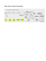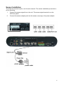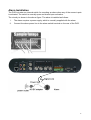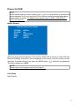
1
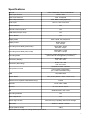
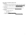
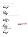
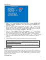
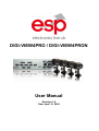
DIGI-VIEW4PRO / DIGI-VIEW4PRON
User Manual
Revision 1.8
Date: April 10, 2008
1
Introduction .......................................................................................................................... 6
Package Contents................................................................................................................ 6
Specifications ....................................................................................................................... 7
Three Steps to Install Surveillance Kit.................................................................................. 8
Installation and Exchange of HDD ....................................................................................... 9
Upload PC Player Program................................................................................................ 10
DVR Front Panel................................................................................................................ 12
DVR Rear Panel ................................................................................................................ 14
Video Input / Output Connection ........................................................................................ 15
Sensor Installation ............................................................................................................. 16
Alarm Installation ............................................................................................................... 17
Power On DVR .................................................................................................................. 18
Initial Screen ............................................................................................................... 18
Live View .................................................................................................................... 18
Display Mode ..................................................................................................................... 20
QUAD View................................................................................................................. 20
Picture in Picture (PIP) ............................................................................................... 20
Sequence View ........................................................................................................... 21
Single Channel View................................................................................................... 21
Record ............................................................................................................................... 22
Playback ............................................................................................................................ 23
Time Search ............................................................................................................... 23
Event Search .............................................................................................................. 24
Playback Operation .................................................................................................... 25
Advanced Playback Operation ................................................................................... 25
DVR Menu and Setup ........................................................................................................ 26
Camera Video Setup .................................................................................................. 26
Title Setup ........................................................................................................... 27
Color Setup.......................................................................................................... 27
Motion Detection.................................................................................................. 28
Status Select........................................................................................................ 29
NTSC/PAL Setup ................................................................................................. 29
Record Setup .............................................................................................................. 30
Record Mode Setup............................................................................................. 31
Continuous Record .............................................................................................. 31
Recording Duration.............................................................................................. 32
2
Motion Record ..................................................................................................... 34
Alarm Record....................................................................................................... 35
Backup Setup ............................................................................................................. 35
PC LINK .............................................................................................................. 36
FLASH DISK........................................................................................................ 37
TCP/IP SETUP (Only for DIGI-VIEW4PRON) ............................................................ 38
Peripheral Setup ......................................................................................................... 41
Buzzer Setup ....................................................................................................... 41
Alarm Setup ......................................................................................................... 42
Sequence Setup .................................................................................................. 43
Password Setup .................................................................................................. 44
VGA Setup (FOR VGA MODEL ONLY)....................................................................... 45
PTZ Setup .................................................................................................................. 46
Date Time Setup ......................................................................................................... 46
Hard Disk Setup.......................................................................................................... 47
Hard Disk Information .......................................................................................... 47
HDD Format ............................................................................................................... 48
HDD Record Mode ..................................................................................................... 48
Factory Setup ............................................................................................................. 49
PC Player Program ............................................................................................................ 51
Install PC Player Program .......................................................................................... 51
Connect DVR to Computer ......................................................................................... 51
Run PC Player Program ............................................................................................. 52
Interface and Operation Indication .............................................................................. 52
Open Video.......................................................................................................... 52
Play Video ........................................................................................................... 54
Audio and Volume ............................................................................................... 55
Save to JPG ........................................................................................................ 55
Save to AVI .......................................................................................................... 55
Turn On/Off Time and Channel Indications .......................................................... 56
Print Screen ......................................................................................................... 56
Internet Operation (Using IE Browser; ONLY FOR DIGI-VIEW4PRON) ............................ 57
Live Video ................................................................................................................... 58
Capture and Record ............................................................................................ 58
Playback .............................................................................................................. 58
Event List ............................................................................................................. 59
Network Setup ............................................................................................................ 60
3
Server .................................................................................................................. 60
Network ............................................................................................................... 61
DVR Setup .................................................................................................................. 63
System ................................................................................................................ 63
Record ................................................................................................................. 65
Auto Log Setup ........................................................................................................... 66
Auto Log Enable .................................................................................................. 67
Auto Log List........................................................................................................ 67
Central Management System (ONLY FOR DIGI-VIEW4PRON) ........................................ 68
Basic Controls ............................................................................................................ 68
DVR Management Panel ............................................................................................ 69
Recording and Capturing Panel.................................................................................. 70
Configuration Panel .................................................................................................... 70
Network Setup ..................................................................................................... 70
DVR Setup........................................................................................................... 73
Event Log ............................................................................................................ 79
CMS Setup .......................................................................................................... 80
About ................................................................................................................... 80
PTZ Panel................................................................................................................... 80
Playback ..................................................................................................................... 80
DVR Finder (ONLY FOR DIGI-VIEW4PRON) .................................................................... 82
DDNS (ONLY FOR DIGI-VIEW4PRON) ............................................................................ 83
Appendix ............................................................................................................................ 87
Troubleshooting .......................................................................................................... 87
4
Regulatory
FCC Certification
This equipment has been tested and found to comply with the limits for a class A digital
device, pursuant to Part 15 of the FCC rules. These limits are designed to provide
reasonable protection against harmful interference when the equipment is operated in a
commercial environment. This equipment generates, uses, and can radiate radio
frequency energy and, if not installed and used in accordance with the instruction manual,
may cause harmful interference to radio communications. Operation of this equipment in a
residential area is likely to cause harmful interference in which case the user will be
required to correct the interference a their own expense.
CE Mark
This product is marked with the CE symbol and indicates compliance with all applicable
EEC directives.
5
Introduction
This system is a professional and easy-installation surveillance and security system
designed for small offices, restaurants, and house owners. Connect any four DC 12V
powered CCTV cameras to the DVR (Digital Video Recorder) and enjoy various functions,
such as recording, retrieving, and network monitoring (only available for Network Model)
video images.
The professional DVR implements the latest smart recording technology, which enables
the DVR to determine the incoming signals of each channel/camera for recording purpose.
If there is no video signal coming from one channel, the DVR does not record that
channel's video; therefore, it does not waste HDD space. The DVR also allows users to
enable or disable recording of each channel. Its pre-recording function is capable of
catching the entire events without missing how the events are happening.
Through USB devices, the DVR provides very convenient methods to back up video
streams to USB flash disks and PCs (not compatible with Apple systems).
Package Contents
CCTV Surveillance System Kit
DVR / Network DVR ×1
IR Remote Control ×1
DVR Power Transformer ×1
DVR Video Output Cable ×1
BNC To RCA Connector ×1
USB Cable ×1
CD ×1
Color, Waterproof, Day & Night Cameras ×4
50 feet DIY cable ×4
(Items are subject to change)
6
Specifications
Item No.
DIGI-VIEW4PRO / DIGI-VIEW4PRON
Video Input Format
NTSC / PAL
Video Input Channel
4CH. Composite
Video Output Channel
2CH. BNC & VGA (Optional)
Audio Input
2CH. In, 2CH. Out; RCA
Motion Detector
Yes
Remote Control Interface
Yes
USB Serial Port (PC-Link)
Yes
Built-in Buzzer
Yes
Display Mode
Each, Quad, PIP, Sequence
Display Frame
NTSC 120 fps
PAL 100 fps
Recording Frame Rate (quad mode)
NTSC Max. 30 fps
PAL Max. 25 fps
Recording Frame Rate (each mode)
NTSC Max. 7.5 fps
PAL Max. 6.25 fps
Recording Mode
Continuous, Motion Detection, and Alarm Event
(All modes can be triggered by schedule.)
Resolution (Display)
NTSC 720 × 480
PAL 725 × 576
Resolution (Recording)
NTSC 704 x 480
PAL 704 x 576
Modified M-JPEG / MPEG4
Compression Format
H.244 Video Compression
(For H.264 DVR Model Only)
HDD
One HDD Rack
Search Mode
Time, Event (Motion, Alarm, Video Loss)
Network Protocol(DIGI-VIEW4PRON Only)
TCP/IP
Ethernet
RJ-45 10M / 100M
Browser
IE 5.0 or above version
OS
Windows 2000 / XP / Vista
Recording Software
Yes
Video Adjustment
Yes
Watch-dog Function
Auto Recovery Capability After Power Outage
Dimension
Weight (Without HDD)
290mm × 300mm × 56mm
3.8kg
Specifications are subject to change without prior notice.
7
Three Steps to Install Surveillance Kit
1. DVR Set Up
a. Decide where to locate the DVR (Please locate it close to TV or monitor if possible)
a. Install HDD if it is necessary (Please refer to Installation and Exchange of HDD)
b. Connect DVR to TV/Monitor (Please refer to Video Output Connection)
2. Camera Setup
a. Decide where to install camera and fix mounting bracket on the ceiling or roof
b. Connect Camera to DVR (Please refer to Video Input Connection)
3. DVR Setting
a. Determine and setup Video Format
i.
Europe Region PAL
ii.
USA NTSC
Please refer to NTSC/PAL Setup Sub Menu.
b. Upload PC Player program. Please refer to Upload PC Player Program.
8
Installation and Exchange of HDD
1.
Open the lid on the top cover.
2.
Loose the screws on the HDD rack.
3.
Connect power cable and transmission bus to the hard drive.
4.
HDD rack will rise. Put the hard drive on the rack and screw it to HDD rack.
5.
Push HDD rack to the bottom and screw it up.
Note: Please leave some space
between the fan and the HDD for
air circulation.
6.
Close the lid on the top cover.
9
Upload PC Player Program
After first installation of HDD or changing a new HDD, we need to upload PC Player
Program to DVR. DVR will automatically copy the PC Player to USB flash devices when
backing up through USB. This leads to review video anytime anywhere.
1.
Turn on the DVR by switching on the power on the back panel.
2.
Plug USB flash drive device to
3.
Go to Factory SETUP menu.
4.
In Factory Setup, highlight USB FORMAT, press “+” or “-” to change NO to YES. And
press “ ” to format USB.
plug on the DVR front panel.
FACTORY SETUP
1. LOAD FACTORY DEFAULT
2. USB FORMAT
3. LOAD PC PLAYER
4. FIRMWARE UPGRADE
ML204GK
:040
JAYS
:015
SKL
:075
[NO]
[YES]
[NO]
[NO]
ENTER: CONFIRM AND RUN
↑↓: SELECT FIELD
+-: CHANGE VALUE
MENU: EXIT
5.
Remove the USB flash drive from DVR and plug it to PC.
Note: Apple System is not applicable
6.
PC automatically detects the USB device. Please open the file window inside USB
flash drive and there are several files. Please delete “PLAYER.PAK” in the USB flash
drive.
.
10
7.
Insert the provided CD to PC, and open the file window. In this disc, there is a file,
called “PLAYER.PAK”. Please copy the file, “PLAYER.PAK”, and paste it to the flash
drive.
8.
Properly remove the flash drive from the PC and plug it to
front panel.
9.
In Factory Setup, highlight Load PC Player and press “+” or “-“ to change No to Yes.
port on the DVR
FACTORY SETUP
1 .LOAD FACTORY DEFAULT
2. USB FORMAT
3. LOAD PC PLAYER
4. FIRMWARE UPGRADE
ML204GK
:011
JAYS
:007
SKL
:040
[NO]
[NO]
[YES]
[NO]
ENTER: CONFIRM AND RUN
↑↓: SELECT FIELD
+-: CHANGE VALUE
MENU: EXIT
10. Press “
” to upload PC Player Program to DVR.
11
DVR Front Panel
I.
II.
III.
I.
Record Video
Quick Backup Video
Playback Video
Reverse Playback Video
Fast Forward Video
Rewind Playback Video
Pause Playback Video
Stop Playback Video
II.
Key Lock
Menu
(Press this button, the
system configuration key pads will be
locked. Users must enter password to
activate system configuration key
pads.)
Channel 1
Channel 2
Channel 3
Channel 4
Quad View
Picture in Picture Display
Sequence Display
USB Link to PC
USB for Flash Drive
III.
Enter
Infrared Receiver
Up
Down
Left
Right
Adjust Value
Adjust Value
12
Keypad Mapping
Button
Stop
Channel 1
Channel 2
Channel 3
Channel 4
Quad
PIP
Sequence
Pause
Reverse Playback
Number
0
1
2
3
4
5
6
7
8
9
13
DVR Rear Panel
Power Switch
Internet Plug
Audio Input / Output
Video Output to Monitor / TV
Power Output for the Camera
Video Input for the Camera
Alarm/Sensor/PTZ I/O Platform
VGA Output
DVR Main Power Input
14
Video Input / Output Connection
15
Sensor Installation
The DVR has 4 sensor inputs, one for each channel. The sensor Installation procedure is
as the following:
I.
Connect the sensor signal line to the unit. The sensor signal terminal is on the
DVR rear panel.
II.
Connect the sensor adaptor jack into the sensor, and plug in the power adaptor.
16
Alarm Installation
The DVR includes one internal switch for sounding an alarm when any of the sensor inputs
is activated. The switch is normally open and closed upon activation.
The circuitry is shown in the above figure. The alarm is installed as follows:
I.
The alarm requires a power supply, which is normally supplied with the alarm.
II.
Connect the alarm power line to the alarm switch terminal on the rear of the DVR.
17
Power On DVR
NOTE:
Factory default setting of video format (NTSC / PAL) is in accordance of the importing
country standard. If you are using this DVR in different video format standard areas,
please adjust the format. To adjust format, please refer to “NTSC / PAL SETUP”
section on Page 29.
Initial Screen
DIGITAL VIDEO RECORDER
SYSTEM
SYSTEM
HDD 1
HDD 1
NET
INITIAL
OK
DETECTING
READY
INITIAL
Above message window appears on the monitor when DVR is turned on. After DVR has
finished initializing, a quad live view is displayed on the screen. Key lock function is also
activated. To disable the key lock, press the MENU button “ ” and enter the password.
The default password is 0000.
NOTE:
Please refer to the keypad match list on Page 13.
Live View
QUAD Mode
18
98% FREE JPEG 30P R
A. DISK SPACE &
RECORD FPS
B. CHANNEL NAME &
RECORDING
STATUS
CAM1
CAM2
CAM3
CAM4
C. RECORDING
INDICATION
D. RECORDING MODE
REC CON
07/07/07 14:12:12
E. CURRENT DATE
AND TIME
A. DISK SPACE & RECORD FPS
98% FREE means HDD is still 98% empty. The number keeps going down if DVR
keeps recording. It shows 99% FREE when HDD is formatted. JPEG is the
recording format. 30P indicates the recording frame rate, and DVR records 30
frames per second (fps). The very last R means RECYCLE mode, and it shows O if
it is ONCE mode.
B. CHANNEL NAME & RECORDING STATUS
CAM2 is the name of this channel. A red dot appears when the channel is recording.
Users can change the name of each channel. Please refer to “TITLE SETUP” on
Page 27.
C. RECORDING INDICATION
REC appears when DVR is recording any channel.
D. RECORDING MODE
It indicates which recording mode is working. CON means Continuous Mode. MON
stands for Motion Detection Mode, and ALM means Alarm Event Mode. Users can
change the setting of each mode and modify the schedule of recording for each
mode. Please refer to “RECORD SETUP” for “RECORD MODE”, “CONTINUOUS
SETUP”, “MOTION SETUP”, and “ALARM SETUP” on Page 30.
E. CURRENT DATE AND TIME
It indicates current date and time. For adjustment, please refer to “DATE TIME
SETUP” on Page 46.
19
Display Mode
DVR provides four different live view modes: QUAD View, Picture in Picture, Sequence
View, and Single Channel View. Press Channel buttons, QUAD, PIP, and SEQ buttons on
the front panel to change the display mode.
QUAD View
Quad View is the default view mode when DVR is turned on.
98% FREE JPEG 30P R
CAM1
CAM2
CAM3
CAM4
REC CON
07/07/07 14:12:12
Picture in Picture (PIP)
PIP Mode allows users to view the primary channel and other three channels at the same
time. To select the primary channel, press “+” or “-“ buttons on the front panel.
PIP
98% FREE JPEG 30P R
CAM2
CAM3
CAM4
CAM1
REC CON 07/07/07 14:12:12
20
Sequence View
In Sequence View, the screen displays through available channels at a certain interval.
Please refer to “SEQUENCE SETUP” on Page 43.
SEQ
CAM1
98% FREE JPEG 30P R
REC CON 07/07/07 14:12:12
Single Channel View
Single Channel View shows one channel constantly.
98% FREE JPEG 30P R
CAM1
REC CON 07/07/07 14:12:12
21
Record
This DVR is equipped with an intelligent recording system, which automatically resumes
previous recording setup and starts recording once the DVR is recovered from electricity
blackout or rebooting. Default recording mode is continuous recording. To adjust record
mode, please refer to “RECORD MODE SETUP” on Page 31.
Press “●” button on the front panel to start recording. If record mode is not set up, a
message “SETUP RECORD” shows on the screen.
Press “■” on the front panel to stop recording. DVR will ask for the password to stop video
recording. The default password is 0000. To set up password, please refer to
“PASSWORD SETUP” on Page 44.
22
Playback
Users can press “ ” button on the front panel to enter playback mode. Below picture
appears on the screen when entering playback mode.
SEARCH
TIME SEARCH
EVENT SEARCH
↑↓:SELECT
ITEM
↑↓
ENTER:SELECT SUB MENU
MENU: EXIT
This DVR provides two playback search functions; they are “TIME SEARCH” and “EVENT
SEARCH”. Use “↑” or “↓” key to select playback function and press “ ” to enter each
function.
In playback mode, press “ ” to pause. Then, press “QC” to activate Quick Copy function
for backing up video to the flash drive. Quick Copy will back up two minute video from the
time point, or backup the whole event.
Time Search
TIME SEARCH
YEAR
MONTH
DAY
HOUR
MINUTE
BEGIN
END
[2007]
[07]
[15]
[02]
[52]
07-06-24 01:50
07-07-21 14:31
↑↓←→:
↑↓←→ SELECT FIELD
+-: CHANGE VALUE
ENTER: RUN MENU: EXIT
BEGIN is the time the DVR starts to record. END is the time that the DVR stops recording.
Use “↑” and “↓” key to select year, month, day, hour, and minute. Use “+” or “-” key to
cycle through all available values.
23
When the time is confirmed, press “
” to view the playback.
Press “■” to end the playback and return to LIVE VIEW.
Press “ ” (Menu Button) to start a new search.
Press “ ” to pause the playback.
Event Search
000
001
002
003
004
005
006
EVENT SEARCH PAGE 001
YY/MM/DD HH/MM/SS
07/08/11
11:15:20
M2
07/08/11
11:15:45
M2
07/08/11
11:17:02
M2
07/08/11
11:22:11
M2
07/08/11
11:33:12
L1
07/08/11
11:34:11
M2
07/08/11
11:35:55
A3
A. PAGE NUMBER
B. EVENT LIST
+-: SELECT ANOTHER PAGE
↑↓:SELECT FIELD
↑↓
ENTER: VIEW EVENT
MENU: EXIT
Press “+” or “-“ to go to other pages. Press “↑” or “↓” to select events, and use “
view the event.
” to
A. PAGE NUMBER
It represents the current page number. The DVR has a total of 143 pages.
B. EVENT LIST
It shows events. Use “↑” or “↓” button on the front panel to select the event. Each event
row shows the event time, event channel and event type. For example:
002 07/08/11 11:17:02 represents Event 2, on 11:17:02 on August 11, 2007.
L1 means Video Loss happening on Channel 1.
M2 means Motion Detection triggered on Channel 2.
A3 means Alarm Event triggered on Channel 3.
When the event is confirmed, press “
” to view the playback.
Press “■” to end the playback and return to LIVE VIEW.
Press “ ” (Menu Button) to start a new search.
Press “ ” to pause the playback.
NOTE:
This DVR is capable of storing more than 1000 events. Event records are deleted if
users format the HDD.
24
Playback Operation
When starting playback, DVR now is in playback mode and displaying. This DVR provides
different speeds of playback, fast backward, fast forward, and frame by frame play back.
CAM1
CAM2
CAM3
CAM4
Playback Indication
>PB 8X
PB END
07/07/07 14:12:12
When in playback mode, the left lower screen shows the operation type:
>PB means playing forward, while <PB means rewind.
8X shows the playing speed. Users can press button “ ” (“ ”) to do fast forward (fast
rewind) of the playback. Multiple press of the button can do fast forward (fast rewind) of
the playback at different speeds; the speed order is x2 x4 x8 x2 x4 x8 x2.
When reaching the end of the video, it shows “PB END” next to the operation type.
Advanced Playback Operation
This DVR provides an advanced playback function by playing back video stream frame by
frame and 1/2 speed playback.
1/2 speed playback
A. Press
B. Press “ ” to do 1/2 speed of playback. Or press “ ” to do 1/2 of rewinding playback.
Frame by frame playback
Press “ ”. Then press “ ” again to do frame by frame playback.
To do rewind frame by frame, users must set the DVR in rewind play and press “
press “ ” again to do frame by frame rewind.
”. Then
25
DVR Menu and Setup
Press “
” (Menu Button) to access main menu.
MAIN MENU
CAMERA VIDEO SETUP
RECORD SETUP
BACKUP VIDEO
TCP/IP SETUP
PERIPHERAL SETUP
DATE TIME SETUP
HARD DISK SETUP
FACTORY SETUP
Basic key indication:
Use “↑” and “↓” button to select each section. Press “
” to go to the section.
Press “ ” (Menu Button) to exit the last page or go to Live View mode. When exiting any
sections, DVR will save the changes.
NOTE:
TCP/IT SETUP option is only available for LAN model DVR
Camera Video Setup
Under CAMERA VIDEO SETUP, users are allowed to name their cameras, to adjust video
quality, to set up motion detection, to set up each camera recording option, to adjust video
format and to set up each camera visibility in live view mode.
CAMERA VIDEO SETUP
TITLE SETUP
COLOR SETUP
MOTION DETECTION
STATUS SELECT
NTSC/PAL SETUP
↑↓:
↑↓ SELECT ITEM
ENTER: SELECT SUB MENU
MENU: EXIT
26
Press “↑” or “↓” button to choose each section. Use “
” button to access the section.
Title Setup
TITLE SETUP
CAM1
CAM2
CAM3
CAM4
[CAM1]
[CAM2]
[CAM3]
[CAM4]
↑↓←→:
↑↓←→ SELECT FIELD
+-: CHANGE VALUE
MENU: SAVE AND EXIT
1.
2.
3.
4.
Use “↑”, “↓”, “→”or “←” button to select each character of cameras.
Press “+” or “-
-”button to cycle through available characters. (0~9, A~Z)
Each channel of camera can have four characters at maximum.
Press “ ” (Menu Button) to save changes and return to the previous page.
Color Setup
COLOR SETUP
CAM
BRIGHTNESS
CONTRAST
SATURATION
HUE
GAIN (1-63)
[01]
[32]
[42]
[38]
[32]
[32]
ADJUST QUALITY OF EACH CAMERA
↑↓:
↑↓ SELECT FIELD
+-: CHANGE VALUE
MENU: SAVE AND EXIT
1. Highlight CAM first to choose camera channel. Press “+” or “-” to select each
channel.
2. Use “↑” or “↓” button to each adjustable item and use “+” or “-” button to cycle
through available values. (Note: 01 Minimum ; 63 Maximum)
3. Press“ ” (Menu Button) to save all changes and go to the previous page.
27
Motion Detection
Under this section, users are allowed to adjust motion detection areas, sensitivity, and
relay in DVR.
The relay serves as a terminal of external alarm to other electrical devices, which is to
activate the alarm or the devices when motion is detected. For example, users may
connect a buzzer alarm to DVR (I/O: Out). When motion is detected by DVR and relay is
on, the buzzer alarm is triggered
Motion Detected
DVR
(Relay Out: ON)
External Alarm or
Electrical Device
MOTION DETECTION
AREA SETTING
SENSITIVITY
(1:MOST)
RELAY OUT
CAM[01]
[RUN]
[07]
[OFF]
ADJUST MOTION DETECTION
↑↓:
↑↓ SELECT FIELD
+-: CHANGE VALUE
MENU: SAVE AND EXIT
1. Highlight CAMERA AREA SETTING section and use “+” or “-
-” to choose each
camera channel. Once channel is confirmed, highlight “RUN” and press “ ” to start
area setting.
+: SELECT -:DIS-SELECT
ENTER: SELECT/ DIS-SELECT ALL
28
A 16 × 12 cell blocks pops out. Use “↑”, “↓”, “←”, and “→” key to select each cell and use
“+” or “-” button to enable or disable motion detecting block. A highlighted cell block
means the motion detection. Users may press “ ” button to select or deselect all cell
blocks.
2. To adjust sensitivity, use “↑” or “↓” key to highlight SENSITIVITY section and press “+”
or “-” key to cycle available sensitivity values, from 1 ~ to 7.
(Note: Value 1 is the most sensitive)
3. To activate relay function, use “↑” or “↓” button to highlight RELAY OUT and press “+”
or “-” button to turn it on or off.
NOTE:
When RELAY OUT is on, the relay in DVR will activate the external buzzer alarm
device which is connected to ALARM OUT on the alarm switch terminal.
4. Press“
” (Menu Button) to save all changes and go to the previous page.
Status Select
In this section, users can choose the channels of video to be visible or invisible in live view
mode.
STATUS SELECT
CH
CAM1
CAM2
CAM3
CAM4
VISIBLE
[ON]
[ON]
[ON]
[ON]
ON/OFF DISPLAY OF LIVE VIDEO
↑↓:
↑↓ SELECT FIELD
+-: CHANGE VALUE
MENU: SAVE AND EXIT
1. Press “↑” or “↓” key to highlight each channel of video.
2. Use “+” or “-” button to choose ON or OFF. ON means the channel is visible in Live
View display; OFF means the channel is invisible in Live View display.
3. Press“ ” (Menu Button) to save all changes and go to the previous page.
NOTE:
DVR still records the video even if the channel is invisible.
NTSC/PAL Setup
The default setting of video format is corresponding to the importing country. In case of
using the DVR in different video format zones, users may need to adjust video format in
this section.
29
NTSC/PAL SETUP
VIDEO SYSTEM
[NTSC]
PLEASE REBOOT DVR
TO APPLY CHANGE
+-: CHANGE VALUE
MENU: SAVE AND EXIT
1. Press “+” or “-” key to choose NTSC system or PAL system.
2. Press“ ” (Menu Button) to save all changes and go to the previous page.
3. Reboot DVR to activate the new setting.
Record Setup
Under this section, users are allowed to setup record mode and schedule, record video
quality and record rate. Use “↑” or “↓” key to choose each section and press “ ” to enter.
RECORD SETUP
RECORD MODE SETUP
CONTINUOUS RECORD
MOTION RECORD
ALARM RECORD
↑↓:
↑↓ SELECT ITEM
ENTER: SELECT SUB MENU
MENU: EXIT
30
Record Mode Setup
RECORD MODE
AM
PM
0--3--6--9-- 0--3--6--9-SUN
MON
TUE
WED
THR
FRI
SAT
CCCCCCCCCCCC
CCCCCCCCCCCC
CCCCCCCCCCCC
CCCCCCCCCCCC
CCCCCCCCCCCC
CCCCCCCCCCCC
CCCCCCCCCCCC
CCCCCCCCCCCC
CCCCCCCCCCCC
CCCCCCCCCCCC
CCCCCCCCCCCC
CCCCCCCCCCCC
CCCCCCCCCCCC
CCCCCCCCCCCC
↑↓←→:
↑↓←→ SELECT FIELD
+-: CHANGE VAULE
MENU: SAVE AND EXIT
1.
Use “↑”, “↓”, “→”or “←” key to select each time cell. Press “+” or “-” button to cycle
through available record modes. Available record modes are: C: Continuous, M:
Motion Detection Recording, A: Alarm/Sensor trigger recording, N: None.
2.
Users may do fast set up by pressing “ ” twice. For example, move the cursor to
Sunday row and choose any cell’s record mode to “M”. Press “ ” twice and the entire
time cells of Sunday become “M” record mode.
3.
Press“
” (Menu Button) to save all changes and go to the previous page.
NOTE:
DVR stops recording when DVR is backing up or linking to PC through USB
Continuous Record
CONTINUOUS RECORD
RECORD QUALITY
RECORD FPS
CAM1 RECORD:
CAM2 RECORD:
CAM3 RECORD:
CAM4 RECORD:
[SUPER]
[JPEG 30]
[ON]
[ON]
[ON]
[ON]
↑↓:
↑↓ SELECT FIELD
+-: CHANGE VALUE
MENU: SAVE AND EXIT
1.
Press “+” or “-” button to cycle through available values. They are: SUPER, HIGH,
31
NORMAL, STANDAR, where SUPER is the highest video quality, and STANDARD is
the lowest video quality.
2.
Use “↑” or “↓” key to highlight “RECORD FPS” and press “+” or “-” button to cycle
through available values. Users can choose compression format from MJPEG and
MPEG4. The available values of FPS for MJPEG are: 1, 2, 4, 8, 15, and 30. 30 is for
the most fluent recording and consumes HDD space the most. The available values of
FPS for MPEG4 are 2, 4, 8, 15, 30, and 60.
3.
Users can enable or disable continuous recording for each channel. Use “+” or “-” to
select “ON” or “OFF”. “ON” means enable the channel recording, and “OFF” means
disable the channel recording.
4.
Press“
” (Menu Button) to save all changes and go to the previous page.
Recording Duration
MJPEG Compression
Quality
Super
High
Normal
Standard
Size per frame (KB)
21
17.9
15.23
12.9
FPS
Size per hour (MB)
Hours for an 160GB HDD
1
74
2,167
2
148
1,084
4
295
542
8
591
271
15
1,107
144
30
2,215
72
1
63
2,543
2
126
1,271
4
252
636
8
503
318
15
944
170
30
1,888
85
1
54
2,988
2
107
1,494
4
214
747
8
428
374
15
803
199
30
1,606
100
1
45
3,528
2
91
1,764
4
181
882
8
363
441
15
680
235
30
1,361
118
32
MPEG4 Compression (Dual Codec Mode Only)
Quality
Super
High
Normal
Standard
Size per frame (KB)
7.0
6.0
5.1
4.3
FPS
Size per hour (MB)
Hours for an 160GB HDD
2
49
3,251
4
98
1,625
8
197
813
15
369
433
30
738
217
60
1,477
108
2
42
3,814
4
84
1,907
8
168
953
15
315
509
30
629
254
60
1,259
127
2
36
4,482
4
71
2,241
8
143
1,121
15
268
598
30
535
299
60
1,071
149
2
30
5,292
4
60
2,646
8
121
1,323
15
227
706
30
454
353
60
907
176
33
Motion Record
MOTION RECORD
RECORD QUALITY
RECORD FPS
EVENT RECORD TIME
PRE RECORD
[SUPER]
[JPEG 30]
[10] SEC
[ON]
↑↓:
↑↓ SELECT FIELD
+-: CHANGE VALUE
MENU: SAVE AND EXIT
1.
Press “+” or “-” button to cycle through available values. They are: SUPER, HIGH,
NORMAL, STANDAR. SUPER is the highest video quality, and STANDARD is the
lowest video quality.
2.
Use “↑” or “↓” key to highlight “RECORD FPS” and press “+” or “-” button to cycle
through available values. The available values of FPS for MJPEG are: 1, 2, 4, 8, 15,
and 30. 30 is for the most fluent recording and consumes HDD space the most. The
available values of FPS for MPEG4 are 2, 4, 8, 15, 30, and 60.
3.
Use “↑” or “↓” key to highlight “RECORD TIME” and press “+” or “-” button to cycle
through available times. They are: 10, 20, 30, 40, 50, and 60 seconds. A record time
of 10 seconds means DVR will record for 10 seconds after the motion is detected.
4.
Use “↑” or “↓” key to highlight “PRE RECORD” and press “+” or “-” button to turn ON
/ OFF the Pre-Record. Pre-record records around 4 sec video before the motion is
detected.
5.
Press“
” (Menu Button) to save all changes and go to the previous page.
34
Alarm Record
ALARM RECORD
RECORD QUALITY
RECORD FPS
EVENT RECORD TIME
PRE RECORD
[SUPER]
[JPEG 30]
[20] SEC
[ON]
↑↓:
↑↓ SELECT FIELD
+-: CHANGE VALUE
MENU: SAVE AND EXIT
1.
Press “+” or “-” button to cycle through available values. They are: SUPER, HIGH,
NORMAL, STANDAR. SUPER is the highest video quality, and STANDARD is the
lowest video quality.
2.
Use “↑” or “↓” key to highlight “RECORD FPS” and press “+” or “-” button to cycle
through available values. The available values of FPS for MJPEG are: 1, 2, 4, 8, 15,
and 30. 30 is for the most fluent recording and consumes HDD space the most. The
available values of FPS for MPEG4 are 2, 4, 8, 15, 30, and 60.
3.
Use “↑” or “↓” key to highlight “RECORD TIME” and press “+” or “-” button to cycle
through available times. They are: 10, 20, 30, 40, 50, and 60 seconds. A record time
of 10 seconds means DVR will record for 10 seconds after the alarm is triggered.
4.
Use “↑” or “↓” key to highlight “PRE RECORD” and press “+” or “-” button to turn ON
/ OFF the Pre-Record. Pre-record records around 7 sec video before the alarm is
triggered.
5.
Press“
” (Menu Button) to save all changes and go to the previous page.
NOTE:
For more details of alarm recording and ALARM MODE SETUP, please refer
to “ALARM SETUP” on Page 42.
To install alarms or sensors, please see “ALARM / SENSOR INSTALLATION”
on Page 16.
Backup Setup
This DVR provides two backup methods. Users can back up video to PC via USB port or
to USB memory storage devices. It also copy the player program to USB memory storage
devices, so users can play the video on any PC (Apple system is not supported) without
installing the player program.
PC Backup Note:
35
1. PC operating system must be Windows 2000 or above.
2. Install PC player program (provided in the disc) to the PC first. Do not
run the PC player program on the CD ROM.
3. Please use the USB port on the rear side of the PC as your platform.
Flash Disk Backup Note:
1. USB 2.0 is recommended.
2. USB memory storage device will be formatted in USB Master Backup.
Please back up all the files before using USB Master Backup.
3. Upload PC player program first. Refer to Page 10 for instructions of
uploading PC player to DVR.
BACKUP VIDEO
PC LINK
FLASH DISK
↑↓:
↑↓ SELECT ITEM
ENTER: SELECT SUB MENU
MENU: EXIT
PC LINK
PC LINK
PC LINK
[RUN]
INSTALL PC PLAYER BEFORE LINK
ENTER: CONNECT
MENU: EXIT
1.
Connect DVR to PC via USB cable provided in the package.
2.
Highlight “RUN” and press “
” to make the connection between PC and DVR. If DVR
36
is successfully connected to PC, you will see a USB mass storage connection icon on
the right and low side of PC screen. DVR screen also shows USB connection is ok.
3.
Double click PC Player icon on the PC to start.
4.
Refer to PC PLAYER Program on Page 51 for PC player operation.
5.
Press “■” to cancel the connection to the PC.
6.
Press“
” (Menu Button) to save all changes and go to the previous page.
FLASH DISK
FLASH DISK
HDD
BEGIN
END
YY/MM/DD HH:MM
07-08-12
09:11
07-08-16
10:22
USB BACKUP
BEGIN
07-08-12
END
07-08-16
09:11
10:22
1.
Use “↑”,“↓”, “←”, or “→” key to highlight USB backup begin & end date and time. Press
“+” or “-” key to cycle through available values.
2.
After confirming the USB backup recording period, press “
WARNING’ page.
3.
“USB MASTER WARNING” page appears on the screen. Press “ ” to format USB
Flash and begin backup. Press“ ” (Menu Button) to cancel and exit the warning
page.
” to enter “USB MASTER
Note:
When the flash drive is full, users can change a new flash drive and
press QC button to resume backing up. Otherwise, press “■” to stop.
37
USB MASTER WARNING
FORMAT USB FLASH DEVICE
USB FLASH DEVICE WILL BE FORMATTED
PRESS ENTER TO RUN
4.
When the backup is completed, press “■” to exit backup progress. Press “
exist and return to live view.
” key to
5.
Unplug the USB memory storage device and connect to any PCs (except Apple
system) to view the video.
6.
Refer to PC PLAYER Program on Page 51 for PC player operation.
NOTE:
When selecting the backup time, make sure the beginning time of video is
valid. If the beginning time of video is not valid, DVR will start from the
nearest time point.
TCP/IP SETUP (Only for DIGI-VIEW4PRON)
System Requirement: Microsoft Windows 2000 or above Operating System, Pentium 4 or
above CPU, 512 MB or above DRAM.
TCP/IP SETUP
TYPE:
PORT:
IP:
G/W:
MASK:
DNS:
MAC:
STATUS:
[STATIC]
[00080]
[192.168.001.002]
[192.168.001.254]
[255.255.255.000]
[192.168.001.001]
00-28-46-00-41-71
CONNECTED
↑↓←→:
↑↓←→ SELECT FIELD
+-: CHANGE VALUE
ENTER: RUN MENU: EXIT
38
Network function lets users to view live video and recorded video via the Internet. It also
supports DDNS function for users if they only have dynamic IP ADSL service from ISP.
Users may do network configuration in this section. The default IP address of the DVR is
192.168.1.1; port number is 80; Subnet mask is 255.255.255.0, and Gateway is
192.168.1.254.
1.
Use “↑” or “↓” to choose network type and its necessary items.
2.
Press “+” or “-” to cycle through available values.
3.
Highlight “APPLY” and press “
4.
Press“
” to apply the new setting.
” (Menu Button) to go to the previous page.
NOTE:
Before setting up, please identify the network connection of the DVR
STATIC IP
Public Static IP Connection
Private / Virtual IP Static IP Connection
Static IP is considered as a fixed IP assigned by ISP (Public IP) or IP share device (Virtual
IP). DVR connecting to static IP needs to be assigned IP address, Gateway, and Subnet
mask.
39
DHCP
The DHCP functions needs to be supported by a router or a cable modem network with
DHCP services. Please apply DDNS when use DHCP connection. For DDNS service,
please refer Page 83.
PPPoE
This PPPoE function needs to have one “username” and one “password” subscribed from
one ISP supplier. Please apply DDNS first when use PPPoE connection. For DDNS
service, please refer to Page 83. After applying DDNS, please also set up username and
password for PPPoE connection. (Refer to Page 61 for PPPoE password and username
setup.)
40
Peripheral Setup
PERIPHERAL SETUP
BUZZER SETUP
ALARM SETUP
SEQUENCE SETUP
PASSWORD SETUP
VGA SETUP
PTZ SETUP
ENTER: SELECT SUB MENU
↑↓:
↑↓ SELECT ITEM
MENU: SAVE AND EXIT
Buzzer Setup
Use “↑” or “↓” to select each buzzer option and use “+” or “-” to change the value.
BUZZER SETUP
KEY BEEP
POWER ON
VIDEO LOSS
ALARM EVENT
MOTION
TIME DURATION
[ON]
[ON]
[OFF]
[OFF]
[ON]
[01] SEC
↑↓:
↑↓ SELECT FIELD
+-: CHANGE VALUE
MENU: SAVE AND EXIT
1. When “KEY BEEP” is on, DVR beeps every time when users press any buttons on the
key pad.
2. When “POWER ON” is on, DVR beeps when it is turned on.
3. When “VIDEO LOSS” is on, DVR beeps when it detects video loss of any channels.
4. When “ALARM EVENT” is on, DVR beeps when external installed alarm/sensor trigger
is activated.
5. When “MOTION” is on, DVR beeps when it detects motion detection.
6. Users can select the length of buzzer time after the events. Press “+” or “-” key to
cycle through available values, from 1 ~ 60 seconds.
7. Press“
” (Menu Button) to go to the previous page.
41
NOTE:
TIME DURATION IS ONLY FOR “MOTION”, “ALARM”, AND “VIDEO LOSS”
EVENTS.
Alarm Setup
This DVR is capable of installing four external input alarm/sensor devices and one output
external alarm device. Use “↑” or “↓” key to choose each setup section and press “ ” to
enter it.
ALARM SETUP
ALARM INPUT
ALARM OUTPUT
ENTER: SELECT SUB MENU
↑↓:
↑↓ SELECT ITEM
MENU: EXIT
Alarm Input Setup
ALARM INPUT SETUP
ALARM IN
1
2
3
4
STATUS
[NO]
[NO]
[NO]
[NO]
OUT
[ON]
[ON]
[ON]
[ON]
FULL
[OFF]
[OFF]
[OFF]
[OFF]
FULL: CHANGE CHANNEL TO FULL
SCREEN WHEN TRIGGERED
↑↓←→
↑↓←→:
←→ SELECT FIELD
+-: CHANGE VALUE
MENU: SAVE AND EXIT
This DVR can accept four alarm/sensor inputs.
1. Press “↑”, “↓”, “→”or “←” to highlight each channel’s alarm setup options.
2. Use “+” or “-” key to cycle through available options.
42
3. Press“
” (Menu Button) to save all changes and go to the previous page.
STATUS
NO: Normal Open means the external alarm/sensor device is short circuit under normal
circumstances. When the circuit is completed, DVR starts to record.
NC: Normal Close means the external alarm/sensor device circuit is completed under
normal circumstances. When the circuit is short, DVR starts to record.
OUT
DVR supports one alarm out. ON means DVR activates the external alarm/sensor device
such as buzzer alarm when the input alarm of that channel is triggered. For example, if
you set Channel 2 ALARM OUT to “ON”, and the input alarm channel 2 is triggered, DVR
activates the external buzzer alarm. (Refer to ALARM/SENSOR Installation on Page 16.)
FULL
DVR displays certain channel of video in full screen if external alarm/sensor is triggered of
that channel. For example, when Alarm In 1 is set to ON, Channel 1 will switch to full
screen (Each Channel Mode) after the input alarm channel 1 is triggered.
Alarm Output Setup
This section allows users to decide the length of alarm output time.
ALARM OUTPUT SETUP
ALARM OUT
1
TIME
[30]
SET UP THE LENGTH OF
ALARM OUTPUT TIME
+-: CHANGE VALUE
MENU: SAVE AND EXIT
1. Cycle available values, 1 ~ 60 seconds, with “+” or “-” key.
2. Press“
” (Menu Button) to save all changes and go to the previous page.
Sequence Setup
Users are able to adjust the interval of displaying each channel in Sequence Display Mode.
43
SEQUENCE SETUP
FULL SCREEN
[01] SEC
SET TIME LENGTH TO CYCLE
THROUGH EACH CHANNEL
+-: CHANGE VALUE
MENU: SAVE AND EXIT
1. Cycle available values, 1 ~ 60 seconds, with “+” or “-” key.
2. Press“
” (Menu Button) to save all changes and go to the previous page.
Password Setup
This DVR allows users to input 4 numerical digits as the system password. DVR asks for
password when users try to release KEY LOCK function and stop recording. The factory
default password is 0000.
PASSWORD SETUP
NEW
CONFIRM
****
****
SELECT NUMBER: 0-9
PASSWORD IS APPLICABLE TO STOP
RECORDING AND DISABLE KEY LOCK
MENU: EXIT
ENTER: SAVE
1. Press Key Pad to set the password. (Refer to the following table.)
2. Use “←” to move backward to correct.
3. Type in both NEW and CONFIRM fields.
4. Press “
” to validate the new password.
5. Press“
” (Menu Button) to validate the new password and go to the previous page.
44
Key Pad Indication
■ -> 0
QUAD -> 5
CH1 -> 1
PIP -> 6
CH2 -> 2
SEQ -> 7
CH3 ->3
∥-> 8
CH4 -> 4
-> 9
NOTE:
The universal password is: QUAD, SEQ, ∥(Pause), QUAD. (5785)
VGA Setup
VGA OUTPUT SETUP
VGA RESOLUTION
[1024X768/60HZ]
+-: CHANGE VALUE
ENTER: APPLY CHANGE
MENU: SAVE AND EXIT
1. Use “+” or “-” key to cycle through available values: 640*480/60Hz, 640*480/75Hz,
800*600/60Hz, 800*600/75Hz, 1024*768/60Hz, and 1024*768/75Hz.
2. Press “
” to apply change.
3. Press“
” (Menu Button) to save all changes and go to the previous page.
45
PTZ Setup
PTZ SETUP
ID
PROTOCOL
BAUD RATE
[01]
[PELCO-D]
[2400]
↑↓:
↑↓ SELECT FIELD
+-: CHANGE VALUE
MENU: SAVE AND EXIT
PTZ supports PELCO-D and PELCO-P protocols. Baud Rate supports 2400, 4800, and
9600.
Date Time Setup
Users can adjust date and time settings in this section.
DATE TIME SETUP
FORMAT
YEAR
MONTH
DAY
HOUR
MINUTE
SECOND
[YY/MM/DD]
[2007]
[07]
[06]
[17]
[16]
[24]
↑↓:
↑↓ SELECT FIELD
+-: CHANGE VALUE
MENU: SAVE AND EXIT
1.
Press “↑”, “↓”, “→”or “←” to select each field to modify.
2.
Use “+” or “-” key to cycle through available options.
3.
After adjustment, press“
page
” (Menu Button) to save all changes and go to the previous
Format is the date format that shows on the live view. Available values are YY/MM/DD,
MM/DD/YY, and DD/MM/YY.
46
Hard Disk Setup
Users are allowed to view HDD information, format HDD, and choose HDD recording
mode. Use “↑” or “↓” key to choose each section and press “ ” to enter.
HARD DISK SETUP
HARD DISK INFORMATION
HDD FORMAT
RECORD MODE: [RECYCLE]
RECYCLE: OVERWRITE HDD
ONCE: STOP RECORDING WHEN HDD FULL
ENTER: SELECT SUB MENU
↑↓: SELECT FIELD
↑↓
+-: CHANGE VALUE
MENU: SAVE AND EXIT
Hard Disk Information
It shows HDD model number and size.
HDD INFORMATION
HDD1: MASTER
MODEL: ST34016A
SIZE: 160.0 GBYTES
Press “
” (Menu Button) to go to the previous page
47
HDD Format
HDD FORMAT
SELECT HDD
CONFIRMATION
[01]
[NO]
SELECT YES AND PRESS ENTER TO
FORMAT HDD
↑↓:
↑↓ SELECT FIELD
+-: CHANGE VALUE
MENU: EXIT
1.
Change NO to YES and press “
” key to format the HDD.
2.
On the screen, it shows the percentage of the progress.
3.
After formatting HDD, DVR goes back to the live view.
HDD Record Mode
HARD DISK SETUP
HARD DISK INFORMATION
HDD FORMAT
RECORD MODE: [RECYCLE]
RECYCLE: OVERWRITE HDD
ONCE: STOP RECORDING WHEN HDD FULL
ENTER: SELECT SUB MENU
↑↓:
↑↓ SELECT FIELD
+-: CHANGE VALUE
MENU: SAVE AND EXIT
1. Press “+” or “-” button to cycle through available modes. Available modes are
RECYCLE and ONCE.
2. Press“ ” (Menu Button) to save change and go to the previous page.
RECYCLE DVR overwrites the HDD when HDD is full.
ONCE DVR stops recording when HDD is full.
48
Factory Setup
Users are able to set DVR to factory default setting, format USB, upload PC player to DVR
HDD, and upgrade the firmware of DVR in this section.
FACTORY SETUP
1. LOAD FACTORY DEFAULT
2. USB FORMAT
3. LOAD PC PLAYER
4. FIRMWARE UPGRADE
ML204GK :012
JAYS
:008
SKL
:044
[NO]
[NO]
[NO]
[NO]
ENTER: CONFIRM AND RUN
↑↓:
↑↓ SELECT FIELD
+-: CHANGE OPTION
MENU: EXIT
1. Load Factory Default allows to restore DVR to its factory default setting. Press “+” or
“-” to choose YES. Press “ ” to run the loading.
2. USB Format allows users to format USB before uploading player to HDD and
upgrades firmware to DVR.
a. Connect Memory Storage device to DVR USB Master Host plug.
b. Press “+” or “-” to choose YES.
c. Press “
” to run the formatting.
3. Load PC Player allows users to backup video files to USB memory storage device and
writing PC player program to it at the same time.
a. Format USB (Note: Users must format USB first.)
b. Remove USB from DVR Master Host plug and connect to PC USB plug.
c. Insert the CD provided in the package.
d. Open Both USB storage and CD ROM discs.
e. Replace player program, called “PLAYER.PAK” in the USB with “PLAYER.PAK” in
the CD ROM disc.
f. Remove USB memory stick from PC properly and connect to DVR USB Master
Host plug.
g. Use “↑”or “↓” to highlight “Load PC Player” section and press “+” or “-” to choose
YES.
h. Press “
i.
” to run the loading.
After the loading is completed, press “■”to exit.
4. Firmware Upgrade: When there is available firmware released, users can update DVR
firmware via USB. Please contact your local distributor for the updated firmware. (Note:
To avoid further confusions, we name the firmware “ROMCODE.ISO”.)
49
Save the firmware temporarily in the PC and follow below steps:
a.
b.
c.
d.
e.
f.
g.
h.
i.
Format USB (Note: Users must format USB first.)
Remove USB from DVR Master Host plug and connect to PC USB plug.
Open Both USB storage device.
Locate the updated firmware saved on the PC, usually called “ROMCODE.ISO”
Replace firmware file, called “ROMCODE.ISO” in the USB drive with
“ROMCODE.ISO” saved on the PC. (Or delete ROMCODE.ISO in the USB drive,
and paste the updated firmware file to the USB drive.)
Remove USB memory stick from PC properly and connect to DVR USB Master
Host plug.
Use “↑”or “↓” to highlight “Firmware Upgrade” section and press “+” or “-” to
choose YES.
Press “ ” to run the upgrading.
After the loading is completed, press “■”to exit.
50
PC Player Program
DVR Player supports DVR series from 4CH to 16CH. It plays videos recorded on the DVR,
takes screenshots, and prints screen through a printer.
Install PC Player Program
1. Insert the CD provided in the package to the CD-ROM.
2. Click DVR PC Player on the menu to install.
(Recommended Screen Resolution: 1024x786)
3. Select your destination directory and click OK.
Connect DVR to Computer
1. Use the USB cable provided in the package to connect DVR and the computer.
2. Plug one end of the USB cable to the PC port on DVR and the other end to the USB
port on PC.
51
PC LINK
PC LINK
[RUN]
INSTALL PC PLAYER BEFORE LINK
ENTER: CONNECT
MENU: EXIT
3. On DVR, select Backup Video USB Slave. Press “
4. When connection is established, a new hardware icon
area on the screen (lower right corner).
” key to establish connection.
is shown in the notification
Run PC Player Program
1. After installation, there is a GKBPlayer icon on the desktop. Double click it to run.
2. The main screen of PC Player is shown.
Interface and Operation Indication
Open Video
1. Click
to open “Open File List” dialog box.
2. Press
and select the DVR disk. Select any *.dvr file and click Open.
All the records are shown on the list.
52
3. Select one of the record and press Open to view the video.
4. Users can directly copy the records to PC without opening them. Press
and a “Copy file to PC” dialog box is shown. Select the
destination path by pressing
. Type the file name and draw the time bar to
set Start Time and End Time. Finally, press
to finish copying.
5. Users can also copy event videos to PC without opening them.
Press
or
shown on the list. Click any one of the events and press
, and the events will be
.
53
Select the destination path, file name, pre-record, post-record time, and press
to copy the event file to PC.
Play Video
After opening the video, the video information is shown on the lower left corner. It shows
the format, Start Time, and End Time of the video.
On the lower right corner, there shows playing statuses, including playing speed, date, and
time.
Operation Buttons:
Start to play
Stop
Reverse playback
Pause / Play frame by
frame
Rewind at 2x, 4x, or 8x
Forward at 2x, 4x, or 8x
Reverse playback at 1/2x
Playback at 1/2x
Go to the beginning
Go to the end
Time Bar: Quick search to certain time point
54
Channel / Display Buttons:
Select certain channel for viewing
Quad View
Nine Channel View
Sixteen Channel View
Audio and Volume
If users use audio in with the DVR, they can adjust the audio channel and volume.
1. Click the buttons of Audio Select to select audio channels.
2. Draw the volume bar to adjust the volume.
pressing the mute button
Users can mute the audio by
.
Save to JPG
Users can save the video screen to a JPG file.
1. Click
, and it shows a “Save as” dialog box.
2. Select destination path and type the file name.
3. Press Save button to save the picture.
Save to AVI
Users can save any certain period of the video to an AVI file.
Click
, and there shows a Time Selecting Dialog.
55
1. Select the channel to record.
2. Draw the time line bar to the time point you want to begin, and press
Start Time.
3. Draw the time line bar to the time point you want to end, and press
End Time.
to set
to set
4. Choose the image quality you like by drawing the slider.
5. Select output mode: an AVI file, or JPEG files by 6 pictures per second.
6. Click
, choose the destination directory.
7. Type the file name for output.
8. Press
to proceed.
Turn On/Off Time and Channel Indications
Press
to turn on or off the Time and Channel Indications on the screen.
Print Screen
Users can print the screen through a printer by pressing
.
56
Internet Operation (Using IE Browser)
After setting the network function for DVR (please refer to TCP/IP SETUP at Page 38),
users can manage / monitor through the IE browser.
Because the application developed for IE is using ActiveX, please install the ActiveX file in
the CD. Click Active-X Plug-in Package to install.
To manage / monitor through the IE browser, please follow the steps:
1. Open IE.
2. Type DVR’s IP address in URL. (If DHCP is used, please refer to CMS at Page 68 to
find DVR’s IP.)
3. An authorizing window pops up. Type username and password (Default: root/root).
Note:
If the DVR is in MENU pages,
the changes of settings on IE
browser will NOT be applicable
to the DVR.
4. A multi management page is shown. Click Link button on the first cell.
5. DVR’s web management interface shows up as below picture.
57
Live Video
In Live Video page, users can see the live view, snap image, record video, and view
playback.
Capture and Record
As soon as entering Live Video page, it displays the live view on DVR.
Channel: Users can change to see different channel or Quad mode by click the buttons
Display: Users can change the solution of the live view. L is the largest, where S is the
smallest.
Capture: Users can snap images from the live view to the computer. Type the destination
path and click Set to apply. And click Capture to save images to the path.
Record: Like Capture, Record saves the live view as video files to the computer. Type the
destination path and click Set to apply. And click Record to save videos to the path.
Playback
In Playback, users are able to review videos saved in HDD of DVR.
58
Channel: Users can change to see different channel or Quad mode by click the buttons
Display: Users can change the solution of the live view. L is the largest, where S is the
smallest.
Search Time: Users can review video at a specific point. Click Run to review.
Star Time: It indicates the very beginning of the recording. Click Run to review it.
End Time: It indicates the end of the recording. Click Run to review it.
Control Buttons: In the bottom row, there are control buttons to operate fast rewind, rewind,
pause, forward, fast forward, and stop. Click STOP to exit playback mode.
NOTE:
When starting Playback, DVR will stop recording and enter playback mode
synchronously.
Event List
The table here lists event recordings on DVR. Users can examine the event happening
previously. Press the button on each event to start the playback.
59
Network Setup
Server
In this section, users can manage network accounts, upgrade DVR firmware, and set up
email notification.
Account
Users can setup maximum five administrator accounts and five user accounts.
Administrators can see the live view, record video to local computers, and change DVR
settings.
Users can only see the live view from the multi management page.
System
In System page, users can do the following operations:
1. Change DVR’s name.
2. Return Network Setting to Factory Default.
3. Upgrade Network Module Firmware.
a. Select firmware from the local computer.
b. Click UPLOAD to upload firmware and upgrade. (Then, click YES on popup
window)
c. Click REBOOT to reboot DVR to complete upgrading procedure.
E-Mail
Users can enable the email notification function by fill the table shown below.
60
DVR will send notification emails when the following situations happen:
1. DVR’s IP or network type is changed.
2. HDD fails.
3. Video loss occurs.
4. Video recovery occurs.
5. Motion detection occurs.
Network
In network section, users can change network settings and DDNS setup. This section
corresponds with TCP/IP SETUP in DVR. (Please refer to TCP/IP SETUP at Page 38)
Type
DVR supports Static IP, DHCP (Dynamic IP), and PPPoE protocols.
If your network environment uses Static IP, please select STATIC IP.
61
In DHCP network environment, please select DHCP CLIENT. Choose ON and click Set to
enable setting.
If PPPoE is used, please select PPPoE. Choose ON and fill in user ID and password
subscripted from your ISP. Then, click Set to enable setting.
DDNS
If a dynamic IP or PPPoE service is used and users want to use DDNS to get access to
DVR, please choose ON and fill Name, ID, and Password. Click Set to enable DDNS for
62
DVR.
To apply for DDNS service, please refer to Page 83.
DVR Setup
System
Here the settings of Time, Camera, HDD, etc. can be modified in this page.
Time
Choose each field to current time and click Set to apply change. Get DVR Time is used to
retrieve DVR’s time setting.
Camera
Each Camera/channel’s setting can be changed here, including Tile, Brightness, Contrast,
Saturation, and Hue.
The button at the top part is used to select channel. Users can drag the red triangles to
change values for each attribute.
63
Reload button is clicked to load the setting before dragging from DVR. Press SET to apply
changes, and Load System Default is clicked to return to factory default setting.
HDD
Here shows the information on HDD in DVR. Users can change Record Mode to Once or
Recycle. Click Set to apply change, and press Get Current Settings to retrieve current
value for it from DVR.
Alarm Input
If users have alarms inputs set up, the settings can be modified in this section. Click Set to
apply changes, and press Get Current Settings to retrieve current values from DVR.
Alarm Output
When alarm output is used, the settings can be modified here. Click Set to apply changes,
and press Get Current Settings to retrieve current values from DVR.
Password
Users can change DVR’s password in this section. Please note ONLY numerals can be
used for password. And four digits must be keyed in at one time.
Version
64
Version shows the current firmware version of DVR.
Factory
Load Factory Default button is clicked to return DVR to original factory default settings.
Record
Record settings, such as Mode, Continuous, Alarm, and Motion, can be changed here.
Mode
This is the recording schedule. Users can set every hour in each of seven days. C is for
Continuous, M is for Motion Detection, A is for Alarm, and N is for None Recording.
Click Set to apply changes, and press Get Current Settings to retrieve current DVR
settings.
Continuous
Users can adjust recording video quality and frame rate in this page.
Click Set to apply changes, and press Get Current Settings to retrieve current DVR
settings.
65
Alarm
In this page, users can adjust the options for Alarm Mode, including Recording Quality,
Recording Frame Rate, Recording Time, and Pre-Record.
Click Set to apply changes, and press Get Current Settings to retrieve current DVR
settings.
Motion
In this page, users can adjust the options for Motion Detection, including Recording Quality,
Recording Frame Rate, Recording Time, and Pre-Record.
Click Set to apply changes, and press Get Current Settings to retrieve current DVR
settings.
Auto Log Setup
In this section, users can set Auto Log Setup for DVR to keep records of Motion Detection,
Alarm Input, Power On, and Record On, etc.
66
Auto Log Enable
Users can enable / disable each option. Click Get Current Settings to retrieve current DVR
settings, and Press Set to apply changes.
Auto Log List
The log of DVR operations will be kept in this page.
67
Central Management System (Only For DIGI-VIEW4PRON)
CMS is the software that manages up to four DVRs in one screen at the same time. The
installation file of CMS is in the CD provided with DVR. Click CMS (Central Management
System) on the menu to run installation procedure.
After installation, double click CMS icon to run it.
A login window will pop up and ask for Account and Password. The default account and
password is root/root.
When correct account/password is entered, the main screen of CMS will show up.
Basic Controls
The time box at the top right corner displays current system time.
buttons at the top left corner control respectively Exit CMS, Full Screen, and
Minimize to Toolbar.
In the middle of the screen shows the live view of each DVR.
68
At the button of the screen, it is a message panel. Event messages will show here.
DVR Management Panel
Click
buttons to select each DVR or Quad mode.
shows current DVR’s IP and name.
Click
view to achieve it.
to add or delete DVR from CMS. Or right click on the live
An Add DVR window will pop up. Fill the correspondent blanks and click OK to add a DVR.
(Default Name and Password is root/root)
If the DVR and your computer are in the LAN (Local Area Network) environment, use
to search the DVR. After searching, double click on the DVR to add it.
69
Channel buttons are used to change different channels or split
display.
Recording and Capturing Panel
CMS records video immediately when this button is pushed.
CMS uses time table to record video.
Press this button to see the time table and arrange recording schedule.
Press this button to snap an image.
Set the destination path for recording and capturing images. (The folder will be
STORAGE.)
Configuration Panel
Note:
If the DVR is in MENU pages,
the changes of settings on CMS
will NOT be applicable to the
DVR.
In this panel, users can change settings for DVR, including Network Setup, DVR Setup,
and CMS Setup.
Network Setup
In network setup section, remote DVR’s network relevant settings can be changed. Please
refer to TCP/IP Setup at Page 38.
70
Users can change the connection types, IP address, mask address, and so on for DVRs.
If DHCP is applicable in the network environment, users can check DHCP Enable box and
push Active New Setting button to set DVR using DHCP.
If the network environment is using PPPoE, users can enter the ID and password in the
PPPoE setting page. To apply settings, check PPPoE Enable box and press Active New
Setting button.
71
In DDNS page, users can set up DDNS for the DHCP (dynamic IP) environment. (Please
refer to DDNS Setting at Page 83.)
In Server page, users can set administrator and user account in the Set User page,
upload firmware and reset default setting in the Set System page,
72
and set email address for notification in the Set E_Mail page.
DVR Setup
In this section, users can see several pages and are able to change the options for DVRs.
Time
DVR date / time can be changed here.
73
Camera
Users can modify each channel’s title, brightness, contrast, saturation, and hue. By
clicking Default, all settings in this page return to factory default values.
Buzzer
Users can enable/disable buzzer for key beep, motion detection, power on, alarm trigger,
and video loss. The beeping length can be changed as well.
HDD
HDD shows the information on the hard drives in DVR. The recording mode can be
changed to either Recycle or Once.
74
Alarm In
In this page, users can change the settings for the alarm input.
Alarm Out
Users can set the settings for alarm output.
75
Sequence
Sequence is the interval between cycling each channel. The available values are from 1
second to 60 seconds.
Password
Users can change the key-lock password for the DVR. Please note that only digits are
acceptable. The password length should be 4 digits.
76
Information
Information page shows the firmware version of the DVR, and users can click Set DVR to
Default to have the DVR return to factory default settings.
Record
Users are able to adjust the compression format, recording frame rate, quality and
recording length. Options to enable/disable pre-record for motion detection and alarm
trigger are available.
77
Message Type
Users can choose which messages will be sent to the email account when it’s triggered.
Event
This page displays the event log on the DVR.
78
Schedule
Recording schedule can be arranged in this page. Click any cell and type C, M, A, or N to
assign value. C is for Continuous, M for Motion Detection, A for Alarm, and N for None.
Event Log
Event log keeps all records happening on DVRs.
79
CMS Setup
CMS login account can be changed here by filling Account, Password, and Confirm.
About
About shows the version and released date of CMS.
PTZ Panel
When the cameras support PTZ control, users can manage them in this panel.
are used to pan,
and zoom out.
are used to tilt, and
are used to zoom in
Playback
Users can review the playback with CMS. Right click on any channel of the live view, and it
shows the menu. Choose Playback to proceed.
80
There is a popup window of operating panel for playback.
1. Search Time: Scroll to a specific time point.
2. Run (under Search Time bar): Start to play playback of the specific time point.
3. Run (Start Time): Play playback from the very beginning of the recording.
4. Run (End Time): Play playback from the end of the recording.
5. <<: Change rewinding speed from 2x, 4x, and 8x.
6. <: Rewind at normal speed.
7. Stop: Stop playback and show the live view.
8. ||: Pause.
9. >: Play playback at normal speed.
10. >>: Change playing speed from 2x, 4, and 8x.
11. 1, 2, 3, …,16: Select certain channel for playback.
12. ALL: See all channels.
13. Cancel: Stop playback and return to the live view. Quit the popup window.
81
DVR Finder (Only for DIGI-VIEW4PRON)
DVR Finder is a program that searches all the DVRs in the LAN. Please insert the CD
provided with the pack, and click DVR Network Finder to install.
Click DVRFinder icon on the desktop to run the program.
After pressing Search DVR button, it shows all the DVRs found in the LAN.
Users can select any DVR in the table, and press Connect DVR button to connect to the
DVR by the IE browser.
Users are able to change the network settings by pressing Edit DVR button.
Clear button is to clear the table of all DVRs found in the LAN.
About button shows the version of DVR Finder.
Exit button is clicked to close the program.
82
DDNS (Only for DIGI-VIEW4PRON)
DDNS (Dynamic DNS) provides dynamic domain names for dynamic IP users. It translates
domain names to dynamic IP address. Dynamic IP users can use DDNS to get access to
their computers without memorizing the IP.
This DVR supports DynDNS (http://www.dyndns.com/) DDNS service.
To use DDNS service, we have to create an account first. Click Create Account under the
Login button.
83
Complete the form and click Create Account button at the bottom to finish the process.
DynDns will send an email to you. Click the link in the email and account creation process
is complete.
Login with your account and go to Services page. Click Dynamic DNS link.
In this page, it shows the description of Dynamic DNS. After reading the information, click
Get Started to set up a Host Name for your IP address.
84
Type the hostname you like, and choose a domain name. Click Use auto detected IP
address link, it fills your current IP automatically.
Finally, press Create Host to finish the process.
85
Now you are able to access your IP by using Hostname.domain. In this example,
digiview.dvrdns.org is mapped to 220.130.57.66.
In DVR Internet Operation (Please refer to Page 61), go to Network Setup->Network.
Choose DDNS and fill the following form. After setting, you can use the domain name to
get to DVR.
86
Appendix
Troubleshooting
1. The DVR cannot detect the hard disk drive (the screen shows HDD NOT FOUND).
Make sure the IDE cable and power cable are connected properly to the hard drive.
Turn on the DVR without connecting CCTV Cameras first. It may caused by consuming
too much power and leads to malfunction of the HDD.
2. There is no image from the cameras.
Make sure the cameras are working all right by connecting them to a CRT monitor
directly. The DVR can only provide at total 2A current to the cameras. If the camera
consumes too much power, please use an individual power for it.
3. The image is incorrect (twisted or flickering).
Make sure the NTSC/PAL setting is set in accordance with the local power system. Go
to MAIN MENU->CAMERA VIDEO SETUP->NTSC/PAL SETUP to adjust.
4. There is no image on the IE browser when connected to the DVR.
Please install the ActiveX plug-in AVMonitor for IE. It can be found in the CD provided
with the pack.
5. When connected to the DVR, the IE browser / CMS shows “disconnect” directly.
The DVR supports maximum four connections at the same time. When the connection
is full, the IE browser or CMS will show “disconnect” directly.
6. I forget the password of the DVR.
The universal password is 5785 (Quad, SEQ, Pause, Quad).
Use the universal password to enter, and change the password right away.
7. I forget the ID/password for the IE / CMS connection.
The universal ID/password the IE/CMS login is 1111/1111.
8. The remote control does not work.
The operating distance from the DVR to the remote control is around five meters.
Please use it within five meters away from the DVR.
If it does not work within the distance, the remote control is out of battery. Please
change a new battery.
9. I am using a router to share network, but the DDNS function does not apply.
The DDNS function is used with DVR connecting to PPPoE or public dynamic IP
directly. If the DVR is working under a router, the DDNS settings should be applied in
the router.
10. What is the default password for the DVR?
The default password for the DVR is 0000 (press ■ four times).
The default ID/password for network administrator is root/root, for users is user/user.
87
Technical Support
0121 7861881
ELECTRONICS LINE UK LTD (ESP)
ADDRESS: UNIT 7 LEVISS TRADING ESTATE, STATION ROAD,
STECHFORD, BIRMINCHAM, B33 9AE, UK
TEL: 0121 7898111
FAX: 0121 6030333
www.espuk.com
CR300000271
88