1
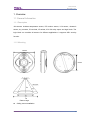
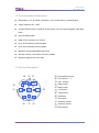
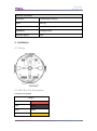
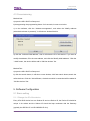
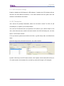
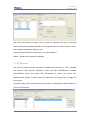
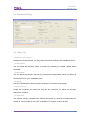
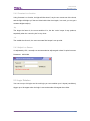
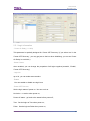
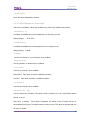
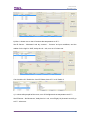
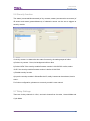
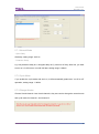
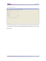
User manual Multi function Sensor SB-CMS-12 in1 www.hdlautomation.com User Manual SB-CMS-12in1 INDEX 1. Overview ....................................................................................................................... 1 1.1 General Information ............................................................................................. 1 1.1.1 Description ................................................................................................. 1 1.1.2 Mounting .................................................................................................... 1 1.2 Functionnalities Description ................................................................................. 2 1.3 Device Description ............................................................................................... 2 2. Safety Instructions......................................................................................................... 3 3. Technical Data ............................................................................................................... 3 4. Installation ..................................................................................................................... 4 4.1 Wiring ................................................................................................................... 4 4.2 HDL Bus Pro Description ..................................................................................... 4 4.3 Commissioning .................................................................................................... 5 5. Software Configuration .................................................................................................. 5 5.1 Basic setting......................................................................................................... 5 5.1.1 Change the ID of the device ...................................................................... 5 5.1.2 LED Indicators Settings ............................................................................. 6 5.2 IR Transmitter ...................................................................................................... 6 5.3 IR Receiver .......................................................................................................... 7 5.4 Sensors setting .................................................................................................... 8 5.4.1 Basic Info ................................................................................................... 8 5.4.2 Constant Lux function ................................................................................ 9 5.4.3 Adjust Lux Sensor ...................................................................................... 9 5.5 Logic Relation ...................................................................................................... 9 5.5.1 Logic Information ..................................................................................... 10 5.5.2 Further Settings of Current Logic .............................................................. 11 5.5.3 Relation.................................................................................................... 12 5.5.4 Trigger targets .......................................................................................... 12 5.5.5 Application ............................................................................................... 13 5.6 Security function ................................................................................................ 16 5.7 Relay Settings .................................................................................................... 16 5.7.1 NormalMode ............................................................................................ 17 5.7.2 Cycle Mode .............................................................................................. 17 5.7.3 Change Modes......................................................................................... 17 5.8 Simulate Test ..................................................................................................... 18 6. NOTES ............................................................................................ 错误!未定义书签。 Multi function Sensor–User Manual User Manual SB-CMS-12in1 1. Overview 1.1 General Information 1.1.1 Description 12in1sensor includes temperature sensor, PIR motion sensor, LUX sensor, ultrasonic sensor, dry contacts, IR received, IR emitter, 2CH 5A relay output and logic block. The logic block can combine all sensors for different applications. It supports HDL security function. 1.1.2 Mounting 110mm 34mm 85mm Detect range Celling mount Installation Multi function Sensor–User Manual 1 User Manual SB-CMS-12in1 1.2 Functionnalities Description Temperature, Lux, IR motion, Ultrasonic, 2 dry contact input, 2 external inputs 2 logic relations: OR、AND 24 logic blocks function, maximum 9 logic inputs, up to 20 control targets in each logic block 2CH 5A Relay output Build PID for constant LUX control Up to 40 IR receiving control targets Up to 240 IR sending control targets Maximum 24 programmable logic blocks Security function, work with the security module Supports upgrade from HDL BUS 1.3 Device Description f ○ b c ○ ○ a ○ j ○ g ○ i h ○ ○ d l e ○ ○ ○ Multi function Sensor–User Manual k ○ a . Programming button ○ b . Dry contact 1、2 ○ c . HDL - Buspro ○ d . Relay output ○ e . Relay output ○ f . LUX sensor ○ g . Temp sensor ○ h . IR Emitter ○ i . PIR sensor ○ j . Ultrasonic sensor ○ k . Ultrasonic sensor ○ l .LED indicator ○ 2 User Manual SB-CMS-12in1 2. Safety Instructions Screw down strength is less than 0.1Nm. Do not make wrong connection on Bus interface, it will damage the Bus interface of thismodule. Do not get AC power into Bus wire, it will damage all devices in the system. Avoid contact with liquids or corrosive gases. 3. Technical Data Electric Parameters: BUS power supply DC12-30V Static power consumption 40mA/DC24V Dynamic power consumption 90mA/DC24V Range of temperature sensor -20℃to 60℃ IR transmit frequency 38KHz IR emission distance 4m Illumination detection range 0-5000Lux PIR sensing range in diameter 6m (install height-3m) Ultrasonic sensor in diameter 8m Environmental Conditions: Working temperature 0℃~45℃ Working relative humidity 40%~98% Storage temperature -20℃~+60℃ Storage relative humidity 10%~93% Approved CE RoHS Multi function Sensor–User Manual 3 User Manual SB-CMS-12in1 Production information: Dimensions 110(Diameter)×33(mm) Weight 206.7(g) Housing material Lens, ABS Installation Ceiling mount Protection degree IP20 4. Installation 4.1 Wiring HDL Buspro 4.2 HDL Bus Pro Description Connector Information buspro DC24V Red COM Black DATA - White DATA + Yellow Multi function Sensor–User Manual 4 User Manual SB-CMS-12in1 4.3 Commissioning Method One: a) open the HDL-BUS Pro Setup tool. b) keep pressing the programming button for 3 seconds, it turns to red color. c) on the software, click the “Address management”, and select the “Modify address (when device button is pressed)”, it will show a window like this: d) click the “Indicate initial address”, then it will show the ID of this device. If you want to modify the address, fill in the new address, and click the “Modify initial address”. Click the “+Add” button, the device will be add in “ON-line devices” list. Method Two: a) open the HDL-BUS Pro Setup tool. b) click the search button, it will show a new window, click fast search button,search the online devices. Click the “Add all”button, the devices which be searched will be added in “ON-line devices” list. 5. Software Configuration 5.1 Basic setting 5.1.1 Change the ID of the device Every HDL-BUS device has one Subnet ID and one Device ID, the Device ID should be unique in its subnet and the Subnet ID should be kept consistent with the Gateway (typically the SB-DN-1IP or HDL-MBUS01IP.431). Multi function Sensor–User Manual 5 User Manual SB-CMS-12in1 5.1.2 LED Indicators Settings Enable or disable the PIR/Ultrasonic LED indicator. If enable, the LED indicator will turn red when the PIR detects movement, or the same indicator will turn green when the ultrasonic sensordetects movement. 5.2 IR Transmitter 12in1 has an IR (infrared) Transmitter, which can be used to control TV, DVD, AC (IR controlled) etc, to replace your normal remotes. You need an IR learnerto learn and upload the IR codes of your normal remote to the 12in1, also there are some codes have been stored in the HDL BUS setup tool, can view them in „All IR Codes‟ window. If now you want to upload some codes to the 12in1, e.g.HDL8 keys code, can follow these steps: a) input a range for the IR code ID, here is 1 to 8, click „Confirm‟ b) select „HDL8 Keys‟ in„All IR Codes‟ window, click „Upload‟, these codes will be shown in „IR codes stored in the hardware‟ list, and the key status will change to „IR-Assigned‟. Multi function Sensor–User Manual 6 User Manual SB-CMS-12in1 Tips: when use buttons to control 12in1 to send out codes,set „key type‟ as universal switch and set the parameter1(Switch no.) correspond to the UV switch number in 12in1, and the parameter2(Switch Status) is ON. Format IR Codes:All the IR codes in the 12in1 will be deleted. Delete:Delete the IR code that is selected. 5.3 IR Receiver Can send UV switch 249 „ON‟ command to enable the IR Receiver, or „OFF‟ to disable from panel or other devices. Generally it works with HDL‟s IR/RFRemote Controller (HDL-MTIRW), which has built-in HDL self-defined IR codes, can control HDL panels/sensors directly, no need to learn IR codes.12in1 can support up to 5 pages, 40 keys in total. For below setting, when press the first button in page 1, it will trigger the dimmer/relay(1-6) to turn on/off channel1. Multi function Sensor–User Manual 7 User Manual SB-CMS-12in1 5.4 Sensors setting 5.4.1 Basic Info - Remarks of dry contacts Remarks are recommended, you may make remarks according to the installation places - On-Site Status You can check the real-time values of sensors by refreshing or enable „Update status automatic‟ - Compensation You can adjust the temp/lux sensors by giving them compensation values, according to the environment of your installation place. - Sensitivity Give the PIR/Ultrasonic sensors proper sensitivity to avoid the wrong trigger - Other Functions Enable the conditions you need here, they are: dry contact1/2, UV switch 1/2 and logic status as a condition - UV Switch ID The sensors and dry contacts have different UV switch ID, send the corresponding UV Switch ID „ON‟ to enable it, and „OFF‟ to disable it from panel or other devices. Multi function Sensor–User Manual 8 User Manual SB-CMS-12in1 5.4.2 Constant Lux function Using Constant Lux function, the light will dim down if, say the sun comes out of the cloud, and the light will bright up if the sun hides behind the cloud again, in a word, you can get a constant brightness(lux). -Kp The larger the factor is, the more sensitive it is, but the „ruder‟ output it may produce, especially when the „control cycle‟ is very short. - Ki The smaller the factor is, the more accurate final output it can provide. 5.4.3 Adjust Lux Sensor It‟s adjusted by HDL, normally not recommended to adjust again unless it‟s quite incorrect. Password:85521566 5.5 Logic Relation You can set up to 24 logics and in each logic you can combine up to 9 inputs (conditions), trigger up to 20 targets when the logic is true and another 20 targets when false. Multi function Sensor–User Manual 9 User Manual SB-CMS-12in1 5.5.1 Logic Information - Power On Delay(0-120s) This parameter is specially designed for „Power OFF Recovery‟ (if you select „true‟ in the „Power OFF Recovery‟, you may get jam on the bus when initializing. you can set „Power On Delay‟ to avoid this.) -Same Column when enabled, you can change the properties of all logics together(„remarks‟, „Enable‟, „Power OFF Recovery‟) -Logic No. up to 24, you can make some remarks -Enable You can enable or disable one logic here -Power OFF Recover Set the logic status of power on. You can set it as: No Action:no action when power on; Power-off status:go back to the status before power off; True:Set the logic as True when power on; False:Set the logic as False when power on; Multi function Sensor–User Manual 10 User Manual SB-CMS-12in1 - On-Site Status Show the value detected by sensors 5.5.2 Further Settings of Current Logic There are 9 conditions, select the conditions you need. The details are as follows. -Temperature(°C) Condition is satisfied when the temperature is in the range you set. Setting Range:-20°C~60°C - Brightness(Lux) Condition is satisfied when the brightness is in the range you set. Setting Range:0~5000 -IR sensor can set „movement‟ or „no movement‟ as a condition. -Ultrasonic sensor can set „present‟ or „absence‟ as a condition. - Dry Contact 1 Use the dry contact 1 as a condition. Disconnect:Take open circuit as a satisfied condition. Connect:Take short circuit as a satisfied condition. -Dry Contact 2 Use the dry contact 2 as a condition. -UV switch(201-248) Use UV switch as a condition. The range of the UV switch no. is 201-248, and the status can be on or off. Auto OFF(0~3600S):If this option is selected, the status of the UV switch will go off automatically every time it is satisfied after the time you set. The range of the time that can be set is 0~3600S. Multi function Sensor–User Manual 11 User Manual SB-CMS-12in1 -Logic You can take the status (true of false) of other logic as a condition.(can‟t be the logic of itself) 5.5.3 Relation If more than one conditions are selected, you can set the logic relationship between them as „AND‟ or „OR‟. - AND Only when all the conditions are satisfied, the logic is „true‟; -OR Once one condition is satisfied, the logic is „true‟. 5.5.4 Trigger targets No matter the logic is true or not, you can trigger the targets you want. -Logic true delay When the logic is true, you can choose to delay some certain time before triggering targets. - Trigger targets when true you can set up to 20 targets to trigger. - Logic false delay When the logic is false, you can choose to delay some certain time before triggering targets. -Trigger targets when false When the logic is false, you can set up to 20 targets to trigger. Multi function Sensor–User Manual 12 User Manual SB-CMS-12in1 5.5.5 Application - Application1 Turn on light when detects movement, and turn it off when no movement after 10s. a) Enable logic No.1, set IR Sensor - Movement as the condition b) Logic true delay is 0s, in „trigger target when true‟ window, input dimmer/relay ID, here is 1-6, parameter 1 is channel 2, parameter 2 is 100. c) Logic false delay is 10s, in „trigger targets when false‟ window, turn off corresponding device channel 2. - Application2 a) When people open the door and come into the meeting room, turn on the lights automatically: Set IR Sensor - „Movement‟ and dry contact1(Suppose dry contact 1 has been connected with a magnetic contact and used to detect the door status) - „Disconnect‟ as input conditions, and the relation for the logic is „AND‟, turn on dimmer(1-6) channel1 when true. Multi function Sensor–User Manual 13 User Manual SB-CMS-12in1 b) After 1 minute turn on the AC and set the temperature as 25℃: Set IR Sensor - „Movement‟ and dry contact1 - „Connect‟ as input conditions, and the relation for the logic is „AND‟, delay time is 1 min, turn on AC when true. Can check the UV Switch No. from IR Emitter, here 25℃ is UV Switch 3. c) 1 minute after people left the room, turn off the lights and set temperature as 27℃: Set IR Sensor - „No Movement‟, delay time is 1 min, turn off light(1-6) channel1 and AC go to 27℃ when true. Multi function Sensor–User Manual 14 User Manual SB-CMS-12in1 Can check the UV Switch No. from IR Emitter, here 27℃is UV Switch 5. d) 3 minutes after people left the room, turn off the AC automatically Set IR Sensor - „ No Movement‟, delay time is 3 min, turn off AC when true. Can check the UV Switch No. from IR Emitter, here OFF is UV Switch 2. Multi function Sensor–User Manual 15 User Manual SB-CMS-12in1 5.6 Security function The states (connected/disconnected) of dry contacts, states (movement/no-movement) of IR sensor and states (present/absence) of ultrasonic sensor can be set as triggers to security module. If use dry contact 1 to detect the door state for security, the setting steps as follow: a) Select „dry contact 1‟ here, its background will turn blue b) Select „NEW‟ if the security module firmware version is 2012/07/05 or after, select „OLD‟ if the security module firmware version is before 2012/07/05. c) Enable security function d) Input the security module‟s Subnet/Device ID, totally 8 areas can be selected, here is area 1. For further configuration, please turn to security module‟s user manual. 5.7 Relay Settings There are 2 relay channels in 12in1, and each channel has 2 modes , Normal Mode and Cycle Mode. Multi function Sensor–User Manual 16 User Manual SB-CMS-12in1 5.7.1 Normal Mode - Open Delay ON delay, setting range: 0-25.0s. - Protection Delay e.g. Set protection delay as 1 min(open delay as 0), now turn off relay, after 25s, you want to turn on it, it will not turn on until 35s later; setting range: 0-60min. 5.7.2 Cycle Mode If you enable the cycle mode and set it on, it will automatically produce an “on-off-on-off” operation; setting range: 1-3600s. 5.7.3 Change Modes Channel 3 and channel 4 are virtual channels, they are used to change the normal mode and cycle mode for channel 1 and channel 2: Multi function Sensor–User Manual 17 User Manual SB-CMS-12in1 5.8 Simulate Test You can simulate the logic you have set up by giving the sensors values or status. (When in simulate state, the real-time values will be bypassed and replaced by values you have given to them) Multi function Sensor–User Manual 18 User Manual SB-CMS-12in1 6. Note ………………………………………………………………………………………………………. ……………………………………………………………………………………………………… ……………………………………………………………………………………………………… ……………………………………………………………………………………………………… ……………………………………………………………………………………………………… ……………………………………………………………………………………………………… ……………………………………………………………………………………………………… ……………………………………………………………………………………………………… ……………………………………………………………………………………………………… ……………………………………………………………………………………………………… ……………………………………………………………………………………………………… ……………………………………………………………………………………………………… ……………………………………………………………………………………………………… ……………………………………………………………………………………………………… ……………………………………………………………………………………………………… ……………………………………………………………………………………………………… ……………………………………………………………………………………………………… ……………………………………………………………………………………………………… ……………………………………………………………………………………………………… ……………………………………………………………………………………………………… ……………………………………………………………………………………………………… ……………………………………………………………………………………………………… ……………………………………………………………………………………………………… ……………………………………………………………………………………………………… ……………………………………………………………………………………………………… ……………………………………………………………………………………………………… ……………………………………………………………………………………………………… Multi function Sensor–User Manual 19