1
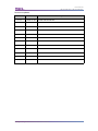
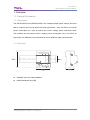
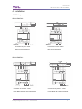
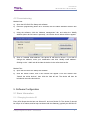
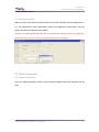
User Manual Intelligent Digital Power Meter SB-DN-PM1P03 SB-DN-PM3P01 www.hdlautomation.com User Manual SB-DN-PM1P03 / SB-DN-PM3P01 Document updates: Version Date V1.0 2015.01.23 Description Finish new document Intelligent Digital Power Meter–User Manual User Manual SB-DN-PM1P03 / SB-DN-PM3P01 INDEX 1. Overview........................................................................................................................................1 1.1 General Information.......................................................................................................... 1 1.1.1 Description...............................................................................................................1 1.1.2 Mounting.................................................................................................................. 1 1.1.3 Serial Numbers.......................................................................................................2 1.2 Functions.............................................................................................................................2 1.3 Device Description.............................................................................................................3 2. Safety precautions....................................................................................................................... 3 3. Technical Data.............................................................................................................................. 4 4. Installation..................................................................................................................................... 4 4.1 Wiring...................................................................................................................................5 4.2 Commissioning...................................................................................................................5 5. Software Configuration............................................................................................................... 6 5.1 Basic Information...............................................................................................................6 5.1.1 Changing the device ID.........................................................................................6 5.1.2 Setting the date...................................................................................................... 6 5.2 Status Information............................................................................................................. 7 5.2.1 Status Information..................................................................................................7 5.2.2 Other Information................................................................................................... 7 5.3 Logic functions................................................................................................................... 8 5.3.1 Logic information....................................................................................................9 5.3.2 Logic Settings......................................................................................................... 9 5.3.3 Relation..................................................................................................................10 5.3.4 Trigger targets...................................................................................................... 10 5.3.5 Application............................................................................................................. 11 5.4 View Power Consumption..............................................................................................12 5.5 Adjust Power Meter.........................................................................................................13 6. Note..............................................................................................................................................14 Intelligent Digital Power Meter–User Manual User Manual SB-DN-PM1P03 / SB-DN-PM3P01 1. Overview 1.1 General Information 1.1.1 Description The SB-DN-PM1P03 and SB-DN-PM3P01 are intelligent digital power meters, which are able to measure and record various electrical parameters. They are able to record the power consumption for 1 year, as well as the current, voltage, power, and power factor. The modules can also accept current, voltage, power consumption, time, UV switch, as logic inputs. An additional current transformer can be added for high power detection. 1.1.2 Mounting Standard 35mm Din Rail Installation Inside Distribution Box (DB) Intelligent Digital Power Meter – User Manual 1 User Manual SB-DN-PM1P03 / SB-DN-PM3P01 1.1.3 Serial Numbers SB-DN-PM1P03 SB-DN-MP3P01 Single phase Triple phase 3 Separate Channels 1 Channel per Phase Max. 16A per channel Max. 10A per channel 1.2 Functions Can measure the voltage, current, power, active power, reactive power, apparent power, power factor, etc. 24 Logic Blocks: The Phase voltage, current of each channel, time, channel electric degree in specified time interval, and Universal Switch can be used as logic inputs to trigger the control targets. The logic relation can be AND&OR. Recorded data can be stored for one year. The record can be checked by month, day, hour, or minute from the application software. Intelligent Digital Power Meter – User Manual 2 User Manual SB-DN-PM1P03 / SB-DN-PM3P01 1.3 Device Description a Live/Neutral line ○ b Current IN/OUT Port ○ c LED Indicator ○ d Programming Button ○ e HDL Buspro ○ f 5A Relay Output ○ 2. Safety precautions Screw down strength is less than 0.4Nm Installation Position: Distribution Box (DB ) Do not make wrong connection on Bus interface, it will damage the Bus interface of this module Never let liquids get into the module, it will damage this device Do connect the module to AC power as this will irreversibly damage all devices in the system. Avoid contact with liquids and aggressive gas Intelligent Digital Power Meter – User Manual 3 User Manual SB-DN-PM1P03 / SB-DN-PM3P01 3. Technical Data SB-DN-PM1P03 SB-DN-PM3P01 Electric Parameters Working voltage DC12~30V BUS power consumption 60mA/DC24V Measuring voltage AC 100~250V Maximum current in each channel 16A 10A Environmental Conditions Working temperature Working relative humidity Storage temperature Storage relative humidity 0℃~45℃ Up to 90% -20℃ to +60℃ Up to 93% Approved: CE RoHS Production Information: Dimensions Housing material Installation Protection degree 72×90×66 (mm) Nylon, PC 35mm DIN rail installation IP20 Intelligent Digital Power Meter – User Manual 4 User Manual SB-DN-PM1P03 / SB-DN-PM3P01 4. Installation 4.1 Wiring SB-DN-PM1P03: Connection for power meter Connection for power meter without current transformer with current transformer SB-DN-PM3P01: Connection of 3 Phase – 4 wire Connection of 3 phase – 4 wire Power Meter without current transformer Power Meter with current transformer Intelligent Digital Power Meter – User Manual 5 User Manual SB-DN-PM1P03 / SB-DN-PM3P01 4.2 Commissioning Method One: a) Open the HDL-BUS Pro Setup tool software. b) Press the programming button for 3 seconds, the LED status indicator will then turn red. c) Using the software, click the “Address management” tab, and select the “Modify address (when device button is pressed)”, the window shown below will then appear: d) Click on “Indicate initial address”, the device ID will then be shown. If you wish to change the address, enter your modification and click “Modify initial address”. Clicking on the “+Add” tab will include the device in the online devices list. Method Two: a) Open the HDL-BUS Pro Setup tool software. b) Click the search button, and a new window will appear. From this window click “Search the online devices”, then click the “Add all” tab. The device will then be included in the online devices list. 5. Software Configuration 5.1 Basic Information 5.1.1 Changing the device ID Every HDL Buspro device has one Subnet ID, and one Device ID. The device ID should be unique in its subnet, and be kept consistent with the Gateway (typically the SB-DN-1IP Intelligent Digital Power Meter – User Manual 6 User Manual SB-DN-PM1P03 / SB-DN-PM3P01 or HDL-MBUS01IP.431). 5.1.2 Setting the date With the built in clock chip, the date and time can be set manually or automatically from a PC. The password to save modifications made to the date/time is 85521566. The time signal can also be broadcast to the system. Warning: It is recommended that the time is set before the system is used. If changes are made while the system is in use the recorded data may be corrupted. 5.2 Status Information 5.2.1 Status Information From the status information window, all of the data collected from the channels can be seen. Intelligent Digital Power Meter – User Manual 7 User Manual SB-DN-PM1P03 / SB-DN-PM3P01 5.2.2 Other Information - Setting Detect Interval Time The interval time to refresh the information has a range from 1-60 seconds. - Clear the Electricity Degree Clear the active and inactive electricity degree to 0, a user must wait at least 13 seconds to ensure effective clearing. Column 1: Clear channel1’s active and inactive electricity degree to 0 Column 2: Clear channel2’s active and inactive electricity degree to 0 Column 3: Clear channel3’s active and inactive electricity degree to 0 Clear total: Clear all of the channels’ active and inactive electricity degree to 0 -Current and Power rate When using a current transformer, the transformer should be connected as shown below: If the current transformation ratio is 10, then the detected current of power meter can reach 10*16A=160A . Intelligent Digital Power Meter – User Manual 8 User Manual SB-DN-PM1P03 / SB-DN-PM3P01 When there is no current transformer, the rate should be 1. 5.3 Logic functions A user can set up to 24 logics, and in each logic 7 inputs (conditions) can be combined. From this 10 targets can be triggered when the logic is true, and another 10 when false. 5.3.1 Logic information - Logic No. Up to 24 logic blocks - Remark A comment can be made for each logic block - Current Status The current logic can be set to be valid or invalid 5.3.2 Logic Settings There are 7 conditions available, allowing a user to select the ones required. The details of the conditions are as follows: - Voltage (V) This condition is satisfied when the voltage is in the range you set. Intelligent Digital Power Meter – User Manual 9 User Manual SB-DN-PM1P03 / SB-DN-PM3P01 - Chn 1 Current (A) This condition is satisfied when chn 1 current is within the range set by the user. - Chn 2 Current (A) This condition is satisfied when chn 2 current is within the range set by the user. - Chn 3 Current (A) This condition is satisfied when chn 3 current is within the range set by the user. - Time Setting A different time type can be set as a condition, some of these conditions allow the combination of channels and the measuring of their power consumption. - Days of the Week Each day of the week can be set as a condition. - UV switch This allows a UV switch to be used as a condition, the setting range is 1-254 and the status can either be on or off. 5.3.3 Relation If more than one condition has been selected, the logic state between them can either be ‘AND’ or ‘OR’. - AND When all the conditions are satisfied, the logic is ‘true’. - OR When only one condition is satisfied, the logic is true. 5.3.4 Trigger targets Regardless of if the logic is true or not, you can trigger the desired targets. - Logic True Delay When the logic is true, a user can choose to delay the triggering of targets. The delay range is 0-36000s. - Trigger when True Intelligent Digital Power Meter – User Manual 10 User Manual SB-DN-PM1P03 / SB-DN-PM3P01 When the logic is true, a user can trigger up to 10 targets. - Logic False Delay If the logic is false, a user can choose to delay the triggering of targets. The delay range is 0-36000 seconds. - Trigger when False When the logic is false, a user can trigger up to 10 targets. 5.3.5 Application One button can be used to enable or disable power saving mode. When in power saving mode and channel A’s detected current is between 10A to 16A during weekend, lights and AC can be turned off. a) One button can be used to send out the UV switch (No.20) to the power meter, this is for enabling/disabling the power saving mode, key mode ’single on/off’, and the parameter1 ‘20’, parameter2 ‘ON’. b) Change the current of channel 1 from 10 A to 16A, then select both ‘Sunday’ and ‘Saturday’. Then click on the UV switch box, and enter 20 as the switch number. Intelligent Digital Power Meter – User Manual 11 User Manual SB-DN-PM1P03 / SB-DN-PM3P01 c) Select the logic relation as ‘AND’, it is advised to set a delay, the delay set here is 10 seconds. d) Turn off the channel 1 and channel 2 relay modules, then turn off the AC in the ‘Trigger when true’ window. Intelligent Digital Power Meter – User Manual 12 User Manual SB-DN-PM1P03 / SB-DN-PM3P01 5.4 View Power Consumption Each channel’s power consumption can be checked every 5 minutes, every hour, every day, every month, and every week using the HDL BUS setup tool. (The consumption can also be checked from the iLife application.) To check the daily power consumption from the 2014-09-01 to 2014-09-04, the following steps must be taken: a) Select Channel No.1 b) Select ‘Query by Day’ in the ‘Format Select’ line c) For the start time select 2014-09-01, and for the end time select 2014-09-04. d) Click ‘Read’ e) View the power consumption of channel 1 on the TChart, the total power consumption can also be seen on the TChart. 5.5 Adjust Power Meter Use a special equipment to adjust the parameters, do not allow to modify them when the power meter is in use. The password is: 85521566. Intelligent Digital Power Meter – User Manual 13 User Manual SB-DN-PM1P03 / SB-DN-PM3P01 6. Note ………………………………………………………………………………………………………. ……………………………………………………………………………………………………… ……………………………………………………………………………………………………… ……………………………………………………………………………………………………… ……………………………………………………………………………………………………… ……………………………………………………………………………………………………… ……………………………………………………………………………………………………… ……………………………………………………………………………………………………… ……………………………………………………………………………………………………… ……………………………………………………………………………………………………… ……………………………………………………………………………………………………… ……………………………………………………………………………………………………… ……………………………………………………………………………………………………… ……………………………………………………………………………………………………… Intelligent Digital Power Meter – User Manual 14 User Manual SB-DN-PM1P03 / SB-DN-PM3P01 ……………………………………………………………………………………………………… ……………………………………………………………………………………………………… ……………………………………………………………………………………………………… ……………………………………………………………………………………………………… ……………………………………………………………………………………………………… ……………………………………………………………………………………………………… ……………………………………………………………………………………………………… ……………………………………………………………………………………………………… ……………………………………………………………………………………………………… ……………………………………………………………………………………………………… ……………………………………………………………………………………………………… ……………………………………………………………………………………………………… ……………………………………………………………………………………………………… ……………………………………………………………………………………………………… Intelligent Digital Power Meter – User Manual 15