1
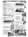
VES Ref I.D. 172
Issue D
Oct 2007
®
USER MANUAL
For the
Weathermaster
and
Extract Fan Models
WM-W, WM-E, WS, WE.
This manual must be read in full before installation, operation and
maintenance of the units supplied.
PLEASE ENSURE THAT THIS INSTRUCTION DOCUMENT
IS PASSED ON TO THE USER OF THE UNIT
A
VES Andover Ltd.
Eagle Close
Chandlers Ford Ind. Est.
Chandlers Ford
Eastleigh
Hampshire
SO53 4NF
Tel.: 08448 15 60 60
Fax: 02380 275696
E-mail: [email protected]
www.ves.co.uk
B
WEEE Directive
At the end of their useful life the packaging and product
should be disposed of via a suitable recycling centre.
Do not dispose of with normal household waste.
Do not burn
©VES Andover Ltd. 2007
No part of this publication may be photocopied or otherwise reproduced
without the prior permission in writing of VES Andover Ltd.
INDEX
INSPECTION ON RECEIPT OF GOODS
3
SAFETY
3
INSTALLATION
4
UNITS WITH HOT WATER COILS
5
ELECTRIC HEATER UNITS
7
MAINTENANCE
8
SPARES
9
AFTER SALES SERVICE
9
DECLARATION OF CONFORMITY
10
WARRANTY
11
All details correct at time of going to press.
We reserve the right to alter specifications without notice. E.&.0.E.
Page 2
INSPECTION ON RECEIPT OF GOODS
Immediately on receipt of any unit check carefully for possible
damage in transit, paying particular attention to heating coil
connections, motor shaft and impeller, and flexible
connections. Please also check unit to ensure that ancillary
items are included, these will normally be packaged inside the
unit.
In the event of any damage having occurred or any item is
found to be missing, it is essential to inform VES Andover Ltd.,
WITHIN 7 DAYS of delivery, quoting S.O. No. and unit type from
its nameplate. After this period we will be unable to accept any
claim for damaged or missing goods.
SAFETY
When installing or using our products the following precautions must be
taken.
Electrical Wiring - All electrical connections to any unit must be carried out
in accordance with the current edition of the I.E.E. Regulations and only
competent electricians should be allowed to effect any electrical work to our
units.
1.
2.
3.
4.
Before attempting to carry out any maintenance work or repair work
on our units, the unit MUST BE COMPLETELY ISOLATED from its
electrical supply. This is particularly important for units with an
electric heater battery. Once the access panels have been removed
there is danger from exposed live elements.
If it is necessary to carry out any assembly operations before
installing the unit, ensure that all fastenings are tightened securely.
The security of fastenings and the integrity of components should be
checked regularly as part of the routine maintenance operation.
Particular attention should be paid to the impeller fixing to the shaft.
Where a unit is installed so that a failure of components could result
in injury to personnel, precautions should be taken to prevent such
an injury.
It is the responsibility of the installer to ensure that the installation complies
with the legal regulations and the current Health and Safety at Work Act.
Page 3
INSTALLATION
The Weathermaster units and silencers are designed to fit
directly to propriety 20/30 mm Mez Flanges. Silencers are supplied loose. Ensure that they are fitted the right way round. Channel bases with AV’s and feet are supplied fitted, all other components are supplied loose, but are easily assembled using the
fastenings supplied.
Access: The lids of all WM units are removable to allow access for installation and servicing.
Voltage: Do not connect any unit to an electrical supply
voltage outside of that indicated on the motor or fan unit name
plate.
Duct Connection: Do not support
ductwork from any Weathermaster
unit.
Rotation
Airflow
Direction of Rotation: Proper
performance will occur if the
impeller is rotating in the correct
direction.
Refer to the diagram for appropriate
fan to ensure correct working details
which then result in the correct
direction of rotation.
Page 4
Motor
Direction of Rotation
for centrifugal fans
UNITS WITH HOT WATER COILS
The Weathermaster WM-W units contain hot water coils with
two rows of copper tubes expanded into aluminium fins. They
are suitable for low pressure hot water at 82°C flow, 71°C
return temperatures, unless otherwise specified and supplied.
Winter Conditions - It is important that water coils are protected against damage from frost during winter. A frost stat
should be installed before the coil to instigate hot water flow
through the coil, or shut the inlet damper if one is fitted.
Air vents and drains are not supplied fitted to the coils. These
should be fitted during installation in the pipework adjacent to
the coil. Should the coil be at a high point in the system it
should be regularly vented, as air locking will progressively
reduce the coil output.
Overheating - It is esential that a run on timer is installed for
the fan so that when the system is shut down the residual heat
radiated by the heating coil is dissipated to avoid damage to
the motor. The hot water supply should be piped to flow to the
bottom connection and outlet via the top connection.
Return
Airflow
Page 5
Flow
Steam Coils - Steam coils are suitable for use with saturated
steam up to 100 psi. The pipework shall be so arranged to
provide adequate drain lines with suitable strainer and steam
trap. All steam and drain lines should be lagged. The supply
shall be taken from the top of the steam main to avoid the
introduction of moisture or air into the coil. The pipe shall be so
arranged so that it does not interfere with coil expansion.
Where steam coils are fitted it is essential that a time delay is
installed in the fan starter control circuit. The fan shall be kept
running for at least two minutes after the coils have been shut
off so that the residual heat is dissipated.
If the pipe run is unduly long and prone to water logging, it
should be properly trapped just before the coil. If the steam is
from a high pressure steam main, it is essential to have a
working pressure valve on the low side to ensure that dangerous
overheating of the air and excessive pressure cannot occur.
DX and Condenser Coils - These must be connected to the
systems in accordance with accepted refrigeration codes of
practice and if fitted upstream to steam or water coils, care
must be taken to ensure that the air temperature does not drop
to below 0°C.
STEAM COIL
DIRECT EXPANSION COIL
Steam In
Liquid In
Gas Out
Airflow
Airflow
Condense Out
Page 6
Drain
ELECTRIC HEATER UNITS
WM-E units contain electric heater batteries and the following
should be checked:
1.
2.
3.
4.
Supply to the heater should be 1ph or 3ph with separate
neutrals, refer to name plate.
Cables should be silicone ruber, fibreglass or similar high
temperature insulated type and be installed to current
I.E.E. Regulations.
The heater is fitted with manual reset high temperature
cutout which has N/C (normally closed) terminals. This
must be connected in series to the main contactor coil
circuit, to isolate the heater in the event of over
temperature (i.e. air flow fialure).
Ensure that there is sufficient earth connection to the
terminal provided.
The minimum air volume as stated on the unit name plate
must be maintained or the thermal overload will trip and will
have to be reset manually.
To remove the electric heater battery, first remove the terminal
box cover, this will give you access to the set screws holding
the main battery.
Speed controllers - If a speed controller is fitted to the system, it
must not switch off the fan independent of the control system, or
allow the air flow to fall below the stated volume on the electric
heater battery.
Thermal Cutout - Every heater is fitted with a thermal cutout
which will break contacts when the duct temperature rises
above 130°C (see checking notes above). This type is
provided to comply with M & E specifications and will require
removal of the terminal box cover to reset. (Supply must be
isolated before removing cover). Maximum switching 12A
single pole.
Page 7
Control System:
A suitable control system should be provided and should include
a timer to keep the fan running for two minutes after the system
has been shut off. The standard VES Andover CPEH panels are
designed for easy operation and connection to all VES electric
heater batteries. Standard heaters are suitable for 1ph or 3ph
control with neutral connection.
Connections:
A 20mm conduit hole is provided in the electric heater terminal
box.
N.B. Terminal pillars are fitted to element studs and care should
be taken not to strain studs which could damage the element
permanently. Always fit an isolator for maintenance of heater.
MAINTENANCE
In general this series of units require very little maintenance.
All fan bearings are supplied fully greased and lubricated.
In the unlikely event of failure, then a new motor kit should be
fitted. We would however advise the following periodic checks:Filters: Filters should be inspected regularly every three months.
If they are found to be heavily soiled or damaged they should be
replaced. Spares for all units are held in stock at the VES factory.
Impellor cleaning: At approximately six monthly intervals, the
impellor should be cleaned using a vacuum cleaner and a soft
brush. Failure to clean the fan from time to time will result in a
loss of performance or cause it to become out of balance.
Dampers: Clean blades, cogs and frames and lubricate with a
PTFE aerosol lubricant or equivalent. Failure to keep dampers
clean, could result in the damper becomming jammed.
Paint Finish: Every twelve months check all painted surfaces to
ensure they have not deteriorated, particularly where adverse
environmental conditions prevail. Repaint if necessary to the
required standard.
Page 8
SPARES
Spares (or direct replacements using improved components) are
normally “off the shelf” and will be held in stock for all units in the
series for a minimum of 10 years.
We would recommend that a spare motor pack be held for
those units which are installed in critical areas or for units that
have to run on a continuous basis.
To obtain a spare motor kit please advise our Sales
Department of the type of unit for which the kit is required. This
can be obtained from the unit name plate.
Recommended Spares: A list of spares recommended to be
held for a specific unit is available if required. Please contact our
Sales Department quoting the unit type and S.O. No., both of
which are obtainable from the unit name plate.
Filters: Replacment filters are available “off the shelf”. These are
sold in boxes of 10. Contact our Sales Department.
AFTER SALES SERVICE
The VES Customer Service Department can undertake a
maintenance check on air handling units as follows:
Replace:
Replace filters
Flexible connections
Check operation of A.V. mounts
Replace missing fasteners
Report:
Prepare a report on the the condition of fan and motor bearings,
cleanliness of coils, condition of A.H.U. case with special regard
to leakage and corrosion.
Please contact the VES Service Manager for scale of charges.
Page 9
Declaration of Conformity
Date:
27 Nov 2002
Product:
Weathermaster and Extract Fan models
Type:
WM-W, WM-E, WS, WE.
Manufacturer: VES Andover Limited
The product above is produced in accordance with EC Council Directives:
89/392/EEC in the version 93/44/EEC (Machinery Directive)
89/336/EEC and amendment 92/31/EEC (Electromagnetic Compatibility
Directive)
73/223/EEC and amendment 93/68/EEC (Low Voltage Directive)
The European Harmonised Standards applied are:
EN 292-1, EN 292-2, EN 294, EN 50082, EN 60204-1
The National Standards applied in particular are:
BS 848 Part 1
Basis of self attestation:
Quality Assurance to ISO 9001-2000, BSI Reg. Firm Cert. No. Q5375
Signature of Manufacturer:
Position of Signatory:
A
Technical Director
Page 10
Warranty
Extended Warranties
All VES Andover Products come with a one year guarantee from date of dispatch,
which covers parts and labour.
You can now extend this with the following options:
Option 1.
FREE extended Warranty
We can offer you a maintenance agreement that keeps this equipment in tip-top
condition.
If you take out this agreement, we will extend the warranty free of charge for up
to 5 years, providing the regular maintenance agreement remains in place.
Option 2.
12-24 Month Extended Warranty
12-24 months from the date of dispatch. This can be covered at a cost of just 3%
of order value. (minimum charge £50.00).
Option 3.
12-36 Month Extended Warranty
12-36 months from date of dispatch. For this cover, the charge is 6% of order
value (Minimum charge £80)
Please State which option you require when you place your order. A transferable
certificate will then be issued to you.
Please note, this offer excludes condensing units. We would be happy to quote
you for these separately.
Register for separate spares reminders and get a 10% discount
Register for this free service and we will automatically send you a regular reminder detailing the consumable spares for this unit, together with their current
list prices.
You will then be entitled to a 10% discount off any spares.
To arrange any of these options.
or
Phone:
Email:
08448 15 60 60
[email protected]
Stating the sales order and reference number from the unit.
Page 11