1
Magellan Weather Station
1
________________________________________________________________________
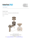
Magellan Weather Station™
User Manual
Version 2.03
Serial Number: __________________
Date Purchased: ________________
All specifications subject to change without notice.
Printed in U. S. A.
Columbia Weather Systems, Inc.
2
Magellan Weather Station
________________________________________________________________________
© Copyright 2005 - 2015 Columbia Weather Systems, Inc. All Rights
Reserved.
Proprietary Notice: Magellan Weather Station, Magellan Portable
Weather Station, Magellan Vehicle-Mount Weather Station,
WeatherMaster software, Weather MicroServer, and Weather Display
Console are trademarks of Columbia Weather Systems, Inc. The
information and drawings contained herein are the sole property of
Columbia Weather Systems, Inc. Use of this publication is reserved
exclusively for customers of Columbia Weather Systems, Inc. and their
personnel. Reproduction of this material is forbidden without the express
written consent of Columbia Weather Systems, Inc.
Columbia Weather Systems, Inc.
Magellan Weather Station
3
________________________________________________________________________
Welcome!
Congratulations on your purchase of a Magellan Weather Station.
Please read this manual completely prior to installation.
Columbia Weather Systems, Inc.
4
Magellan Weather Station
________________________________________________________________________
Important Notice: Shipping
Damage
BEFORE YOU READ ANY FURTHER, please inspect all system
components for obvious shipping damage. The Magellan is a high
precision instrument and can be damaged by rough handling. Your unit
was packaged to minimize the possibility of damage in transit. Please
save the shipping container for any future shipment of your Magellan
sensor.
In the event your order arrives in damaged condition, it is important that
the following steps be taken immediately. The title transfers automatically
to you, the customer, once the material is entrusted to the transport
company.
NOTE: DO NOT RETURN THE INSTRUMENT TO COLUMBIA
WEATHER SYSTEMS until the following steps are completed. Failure to
follow this request will jeopardize your claim.
1. Open the container and inspect the contents. Do not throw away
the container or any damaged parts. Try to keep items in the
same condition as originally received.
2. Notify the transport company immediately.
3. Request the transport company’s representative inspect the
shipment personally.
4. After inspection, request a Return Materials Authorization (RMA)
from Columbia Weather Systems by calling (503) 629-0887.
5. Return approved items to us at the following address:
Columbia Weather Systems, Inc.
5285 NE Elam Young Parkway, Suite C100
Hillsboro, OR 97124
6. After a repair evaluation, an estimate of the cost of repair will be
sent to you.
Columbia Weather Systems, Inc.
Magellan Weather Station
5
________________________________________________________________________
ESD Protection
Electrostatic Discharge (ESD) can cause immediate or latent damage to
electronic circuits. The Magellan is adequately protected against ESD for
its intended use. However, it is possible to damage the product by
delivering electrostatic discharges when touching, removing, or inserting
any objects inside the equipment housing.
To avoid delivering high static voltages yourself:
1. Handle ESD sensitive components on a properly grounded and
protected ESD workbench. When this is not possible, ground
yourself with a wrist strap and a resistive connection cord to the
equipment chassis before touching the boards. When neither of
the above is possible, at least touch a conductive part of the
equipment chassis with your other hand before touching the
boards.
2. Always hold the boards by the edges and avoid touching the
component contacts.
Columbia Weather Systems, Inc.
6
Magellan Weather Station
________________________________________________________________________
Columbia Weather Systems, Inc.
Magellan Weather Station
7
________________________________________________________________________
Table of Contents
WELCOME! ..................................................................................3
IMPORTANT NOTICE: SHIPPING DAMAGE .......................4
ESD PROTECTION ............................................................................................. 5
SECTION 1: INTRODUCTION ................................................11
THE MAGELLAN WEATHER STATION ............................................................. 11
SPECIFICATIONS .............................................................................................. 12
Input Voltage.............................................................................................. 12
PRINCIPLES OF MEASUREMENTS ..................................................................... 13
Temperature ............................................................................................... 13
Humidity..................................................................................................... 13
Barometric Pressure .................................................................................. 13
Wind Measurement .................................................................................... 13
Fluxgate Compass...................................................................................... 13
SECTION 2: PHYSICAL DESCRIPTION ...............................15
MAGELLAN SENSOR TRANSMITTER ................................................................ 15
INTERFACE MODULE ...................................................................................... 16
SURGE/LIGHTNING PROTECTOR...................................................................... 17
WEATHERMASTER SOFTWARE (OPTIONAL) ................................................ 18
WEATHER DISPLAY CONSOLE (OPTIONAL) .................................................... 19
WEATHER MICROSERVER (OPTIONAL) ........................................................... 20
SECTION 3: FIXED MOUNT INSTALLATION ....................21
FIXED MOUNT SYSTEM CONFIGURATIONS ..................................................... 21
Wireless System with Weatherproof Enclosure: ........................................ 22
INSTALLATION OVERVIEW.............................................................................. 23
UNPACKING THE UNIT .................................................................................... 23
Installing the Mast ..................................................................................... 25
Location ..................................................................................................... 25
Mounting Method ....................................................................................... 25
Routing Cable ............................................................................................ 25
Installing the Magellan Sensor Transmitter .............................................. 27
Site Selection: ............................................................................................ 27
North Alignment ......................................................................................... 27
Installing the Mounting Adapter ................................................................ 28
Installing the Surge Arrestor...................................................................... 30
Connecting the Sensor Transmitter to the Interface Module ..................... 31
OPTIONAL SENSOR MOUNTING HARDWARE ................................................... 32
Telescoping Tripod and Tiedown Kit ......................................................... 32
Specifications ............................................................................................. 33
Columbia Weather Systems, Inc.
8
Magellan Weather Station
________________________________________________________________________
Sensor Mast................................................................................................ 34
Roof Mounting ........................................................................................... 34
Wall Mounting ........................................................................................... 35
SECTION 4: VEHICLE MOUNT INSTALLATION ..............37
VEHICLE MOUNT SYSTEM CONFIGURATIONS ................................................. 37
INSTALLATION OVERVIEW.............................................................................. 37
UNPACKING THE UNIT .................................................................................... 38
INSTALLING THE TELESCOPING MAST AND VEHICLE-MOUNT BRACKETS ......... 39
INSTALLING THE VEHICLE MOUNT SENSOR CONNECTOR AND ROUTING CABLE 40
INSTALLING THE INTERFACE MODULE............................................................ 41
CONNECTING THE WEATHER DISPLAY CONSOLE AND COMPUTER ................. 42
INSTALLING THE SENSOR TRANSMITTER AND NORTH ORIENTATION .............. 43
North Alignment ......................................................................................... 43
SECTION 5: PORTABLE INSTALLATION...........................45
UNPACKING THE UNIT .................................................................................... 46
Magellan Portable Carrying Case ............................................................. 47
TELESCOPING TRIPOD AND TIEDOWN KIT ...................................................... 48
Tripod Parts List: ....................................................................................... 49
Specifications ............................................................................................. 50
RS-232 Interface Module ........................................................................... 51
Set Up Instructions..................................................................................... 52
Site Selection: ............................................................................................ 52
Mast Set Up and Sensor Alignment: .......................................................... 52
Transportation Case and Sensor Plug-In .................................................. 53
Battery Power System ................................................................................ 53
OPERATION ..................................................................................................... 53
MONITORING .................................................................................................. 53
SECTION 6: OPERATION ........................................................55
MAGELLAN SENSOR TRANSMITTER INTERFACE ............................................. 55
Magnetic Declination................................................................................. 55
Parameter Units ......................................................................................... 56
SECTION 7: CALIBRATION....................................................59
FACTORY CALIBRATION ................................................................................. 59
TEMPERATURE AND PRESSURE READING ADJUSTMENTS................................ 59
SECTION 8: MAINTENANCE .................................................61
SECTION 9: USER SUPPORT INFORMATION ...................63
LIMITED WARRANTY ...................................................................................... 63
EXCLUSIONS ............................................................................................ 63
RETURN FOR REPAIR PROCEDURE .................................................................. 64
Columbia Weather Systems, Inc.
Magellan Weather Station
9
________________________________________________________________________
REFERENCE ...............................................................................67
GLOSSARY ...................................................................................................... 67
Aspirating Radiation Shield ....................................................................... 67
Barometric Pressure .................................................................................. 67
Celsius Temperature Scale......................................................................... 67
Dew Point .................................................................................................. 67
Fahrenheit Temperature Scale................................................................... 67
Heat Index .................................................................................................. 67
Relative Humidity....................................................................................... 67
Sea Level Pressure ..................................................................................... 68
Wind Chill .................................................................................................. 68
UNIT CONVERSION ......................................................................................... 69
Speed .......................................................................................................... 69
Temperature ............................................................................................... 69
Distance ..................................................................................................... 69
Pressure ..................................................................................................... 69
TABLES AND FORMULAS ................................................................................. 70
Wind Chill Chart ........................................................................................ 70
Wind Chill Equation .................................................................................. 71
Heat Index .................................................................................................. 72
Dew Point .................................................................................................. 73
Columbia Weather Systems, Inc.
10
Magellan Weather Station
________________________________________________________________________
Columbia Weather Systems, Inc.
Magellan Weather Station
11
________________________________________________________________________
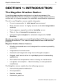
SECTION 1: INTRODUCTION
The Magellan Weather Station
For cutting-edge weather monitoring in a harsh environment, the
Magellan Weather Station combines a rugged multi-parameter weather
sensor with an internal compass for automatic wind direction alignment.
The all-in-one Magellan sensor module integrates:
•
A sonic anemometer for wind speed measurement
•
Multi-element sensor for highly accurate and stable temperature
readings
•
Fast-response, capacitive relative humidity sensor
•
State-of-the-art barometric pressure sensor
•
Internal fluxgate compass for automatic alignment of wind
direction
Weather monitoring options include WeatherMaster™ Software and the
Weather MicroServer™ for internet-ready weather data and industrial
protocols.
Magellan Weather Station Features
•
Weather-protected sensor unit designed for maximum portability
and utility
•
Integrated sonic wind sensor
•
Automatic self-alignment using internal fluxgate compass
•
Rugged metal construction for rapid deployment in demanding
applications
•
No mechanical components means virtually no maintenance
•
Low power consumption – ideal for battery or solar-powered
installations
The Magellan sensor module has the following sensors:
•
Sonic Wind speed and direction
•
Air temperature
•
Relative humidity
•
Barometric pressure
Columbia Weather Systems, Inc.
12
Magellan Weather Station
________________________________________________________________________
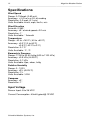
Specifications
Wind Speed
Range: 0-134mph (0-60 m/s)
Accuracy: +/-0.5 m/s or 5% of reading
Resolution: 0.2 mph (0.1 m/s)
Units Available: knots, mph, km/hr, m/s
Wind Direction
Azimuth: 0-360°
Accuracy: ±5° at wind speed >2.2 m/s
Resolution: 1°
Units Available: ° Azimuth
Temperature
Range: -40 to +140°F (-40 to +60°C)
Accuracy: ±0.2°C (0 to 60°C)
±0.5°C (-40°C to 0°C)
Resolution: 0.1°C
Units Available: °F, °C
Barometric Pressure
Range: 17.50 to 32.50 InHg (600 to 1100 hPa)
Accuracy: ±0.5 hPa (At 25°C)
Resolution: 0.1 hPa
Units Available: Kpa, mbar, InHg
Relative Humidity
Range: 0 - 100%
Accuracy: ±3% (At 25°C)
Resolution: 1%
Units Available: %RH
Compass
Accuracy: ±2°
Resolution: 1°
Input Voltage
Sensor Input: 8 to 36 VDC
Current Consumption: 40mA typical@ 12VDC
Columbia Weather Systems, Inc.
Magellan Weather Station
13
________________________________________________________________________
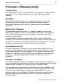
Principles of Measurements
Temperature
The temperature sensor in the Magellan uses a precision triple-element
thermistor. This provides highly accurate and stable temperature
readings.
Humidity
The relative humidity sensor is a capacitive polymer sensor. The
construction of the humidity sensor element provides excellent
resistance to wetting, dust, dirt, oils, and common environmental
chemicals.
Barometric Pressure
The barometric pressure sensor is a stable transducer using nanotechnology, yielding a linear and repeatable sensor with low hysteresis.
The piezoresistive pressure sensor module is mounted on a small
electronic circuit board.
A microcontroller controls the operation of the sensor and the data
interface. The microcontroller polls the pressure sensor module once per
second for the barometric pressure and ambient temperature. The raw
readings are temperature corrected by the microcontroller.
Wind Measurement
A unique folded-path, low-power sonic anemometer operates on the
principle that the speed of the wind affects the time it takes for sound to
travel from one point to a second point. If the sound is traveling in the
direction of the wind, then the transit time is decreased. If the sound is
traveling in a direction opposite the wind, then the transit time is
increased.
Fluxgate Compass
The internal compass module is low power and compact. It employs a
pair of magneto-inductive sensors which change inductance with varying
magnetic field strengths, to sense the Earth’s magnetic field.
The microprocessor measures the output of the internal compass and
then corrects wind direction data for the orientation of the sensor. The
output of the wind direction is relative to magnetic North. A user
programmable value of Magnetic Declination may be entered through
terminal mode to enable output relative to True North rather than
Magnetic North.
Columbia Weather Systems, Inc.
14
Magellan Weather Station
________________________________________________________________________
Columbia Weather Systems, Inc.
Magellan Weather Station
15
________________________________________________________________________
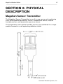
SECTION 2: PHYSICAL
DESCRIPTION
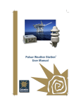
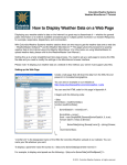
Magellan Sensor Transmitter
The Magellan Sensor Transmitter is an all-in-one sensor unit containing
sonic wind speed and direction sensor, temperature sensor, relative
humidity sensor, and barometric pressure sensor.
The temperature and relative humidity sensors are combined in a single
module housed in a self-aspirating radiation shield.
Columbia Weather Systems, Inc.
16
Magellan Weather Station
________________________________________________________________________
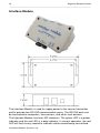
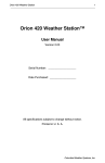
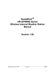
Interface Module
The Interface Module is used to supply power to the sensor transmitter
and to provide two RS-232 communication ports. The RS-232 ports can
be connected to computers, transceivers, and other such devices.
The Interface Module has two LED indicators. The green LED is a power
indicator and the red LED is a data indicator. In normal operation, the red
LED will flash every second to indicate a data record being transmitted.
Columbia Weather Systems, Inc.
Magellan Weather Station
17
________________________________________________________________________
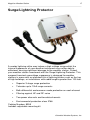
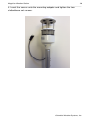
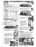
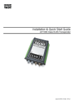
Surge/Lightning Protector
A nearby lightning strike may induce a high voltage surge which the
internal suppressor of your weather instrument may not be able to
withstand, causing significant damage to the weather station. Protect
your weather station investment with the Surge/Lightning Protector. This
compact transient overvoltage suppressor is designed for weather
stations in areas with an elevated risk of lightning strikes such as the top
of high buildings, or installations with cable lengths greater than 100 feet.
•
Superior 3-stage surge protection
•
Tolerates up to 10kA surge currents
•
Both differential and common mode protection on each channel
•
Filtering against HF and RF noise
•
Two power channels and two data channels
•
Environmental protection class IP66
Catalog Number: 8355
Includes adjustable mounting kit
Columbia Weather Systems, Inc.
18
Magellan Weather Station
________________________________________________________________________
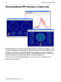
WeatherMaster
Software (Optional)
WeatherMaster is professional grade weather monitoring software. This
software package is designed for specialized markets that require robust
weather calculations, interoperability with computer models, and data
interfaces to other industrial systems. WeatherMaster utilizes Microsoft
Access database for easy data access and manipulation.
Please refer to the WeatherMaster user manual for installation and
operation procedures
Columbia Weather Systems, Inc.
Magellan Weather Station
19
________________________________________________________________________
Weather Display Console (Optional)
Displays weather information • Designed to be viewed clearly from a
distance • Industrial grade WVGA touchscreen.
Seven-inch, TFT color LCD panel with 800 x 480 pixel resolution.
Performs computations for wind chill, heat index and other calculated
parameters • 200MHz ARM9 CPU
Serial or Ethernet connection: Connects directly to weather station with
serial port or connects to a Weather MicroServer over a network utilizing
an existing Ethernet infrastructure -- no extra wiring. The MicroServer
configuration also allows for data from one weather station to be
monitored from multiple display consoles at various locations.
Screens can be factory-customized to meet specialized market and
industry requirements.
The Weather Display is also available in a 19” rack-mount chassis and a
panel-mount configuration.
Please refer to the Weather Display Console user manual for more
information.
Columbia Weather Systems, Inc.
20
Magellan Weather Station
________________________________________________________________________
Weather MicroServer (Optional)
The Weather MicroServer uses a small computer board that runs an
embedded Linux operating system.
The MicroServer has 32MB flash memory for operation and 8 GB SD
card for data logging.
The Magellan transmitter connects to the MicroServer via COM1.
The MicroServer has two RS-232 COM ports and an Ethernet port.
The MicroServer offers the following:
•
XML Weather Data
•
FTP weather data in XML or CSV format
•
Modbus/TCP, Modbus RTU (Serial RS-485) interfaces
•
SNMP, BACnet, DNP3 interfaces
•
Weather Underground & Anything Weather interface
•
CWOP interface
•
Years’ worth of data logging at 1-minute interval
•
Interface to optional visibility, solar radiation sensors, and
temperature sensors
Please refer to the Weather MicroServer user manual for more
information.
Columbia Weather Systems, Inc.
Magellan Weather Station
21
________________________________________________________________________
SECTION 3: FIXED MOUNT
INSTALLATION
Fixed Mount System Configurations
The Magellan Fixed Mount Weather Station can be installed in multiple
configurations depending on communication options, power availability
and viewing options.
Cabled System:
Columbia Weather Systems, Inc.
22
Magellan Weather Station
________________________________________________________________________
Wireless System with Weatherproof Enclosure:
The following is an example of a wireless configuration.
Columbia Weather Systems, Inc.
Magellan Weather Station
23
________________________________________________________________________
Installation Overview
Unpacking the System
Installing the Mast
Installing the Sensor Transmitter
Installing the Surge Arrestor
Installing the Interface Module
Connecting the Sensor Transmitter to the Interface Module
Connecting to MicroServer, Weather Display and Computer (refer to
Section 3: Fixed Mount Installation)
Unpacking the Unit
Unpack the Magellan weather station and verify that all parts are
included.
1. Standard system includes:
Magellan Sensor Transmitter
50 ft sensor cable + additional cable length if ordered
Interface Module
(2) 3-position terminal blocks
Interface module power supply
User Manual
7-foot RS-232 cable + additional cable length if ordered
2. Weather Display Console (Optional)
Display Console
Power supply
6-foot RS-232 cable + additional cable length if ordered
User manual
3. WeatherMaster software and user manual (Optional)
4. Weather MicroServer (Optional)
MicroServer
Power supply
6-foot Ethernet cable
Columbia Weather Systems, Inc.
24
Magellan Weather Station
________________________________________________________________________
User manual
Inspect all system components for obvious shipping damage (Refer to
“Important Notice: Shipping Damage” in case of damage).
NOTE: Save the shipping carton and packing material in case the unit
needs to be returned to the factory. If the system does not operate or
calibrate properly, see Maintenance and Troubleshooting sections, for
further instructions.
Columbia Weather Systems, Inc.
Magellan Weather Station
25
________________________________________________________________________
Installing the Mast
There are three acceptable methods for mounting the mast to a roof or
building structure: Sloped roof mounting, flat roof mounting or wall
mounting. See Optional Sensor Mounting Hardware for more
information.
Location
Do not attach the sensor transmitter to a radio transmitting mast or
tower.
Select a mounting location that will allow the sensor cable to be routed
away from other data cables to avoid interference. Do not mount sensors
close to power lines. For normal roof mounting, the recommended
minimum distance from power lines is 25 ft. (8 m). Use extreme caution
when working close to power lines.
Mounting Method
Choose the appropriate mounting method for the installation and obtain
any necessary mounting hardware. Refer to Optional Sensor Mounting
Hardware section for information on optional sensor mounting hardware
and accessories which are available from the factory.
If the mounting hardware is not obtained from the factory, be certain to
use metal parts which are plated or galvanized to assure maximum
longevity.
Secure the mast to the roof, using guy wires with sufficient tensile
strength or to building wall using a wall-mount hardware kit.
Routing Cable
Use plastic tie wraps to secure the cable to mast, particularly at the mast
base. Tighten the tie wraps securely and clip off any excess length with a
wire cutter tool.
Once the Magellan sensor transmitter has been installed route the cable
back to the Interface Module or weatherproof enclosure.
CAUTION: There may be electric wires in the wall. When routing cable
through walls, we recommend that you shut off the electricity in the
room(s) where you are drilling.
Any mast or tower should always be properly earth grounded to minimize
electrical storm damage. The use of a properly grounded metal mast or
tower, however, does not insure protection from electrostatic discharge.
These items could become electrically charged resulting in damage to
the sensors and/or console. This could damage the system in the event
of an electrical storm.
Columbia Weather Systems, Inc.
26
Magellan Weather Station
________________________________________________________________________
Note: If the standard 50 ft. cable provided with the sensor transmitter is
not long enough, it may be extended by splicing on an appropriate length
of 22-gauge, stranded, seven conductor shielded cable with the same
color code. When cutting and splicing, insure good contacts, proper color
coding of the terminal leads, and a good seal. (A good solder splice, and
water proof insulation are essential; merely twisting the respective wires
together is not adequate.) Additional cable (Catalog No. 81547) is
available from the factory.
Columbia Weather Systems, Inc.
Magellan Weather Station
27
________________________________________________________________________
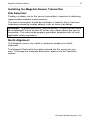
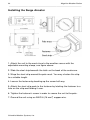
Installing the Magellan Sensor Transmitter
Site Selection:
Finding a suitable site for the sensor transmitter is important in obtaining
representative ambient measurements.
The sensor transmitter should be installed in a location that is free from
turbulence caused by nearby objects, such as trees or buildings.
WARNING: To protect personnel (and the device), a lightning rod should
be installed with the tip at least 40 inches (one meter) above the sensor
transmitter. The rod must be properly grounded, compliant with all local
applicable safety regulations.
North Alignment
The Magellan sensor has a built-in electronic compass for North
alignment.
The Magnetic Declination has been entered into the sensor for your
area. To change the magnetic declination, please see the Operation
section.
Columbia Weather Systems, Inc.
28
Magellan Weather Station
________________________________________________________________________
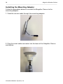
Installing the Mounting Adapter
Follow the procedure below to connect the Magellan Sensor to the
mounting adapter:
1. Feed the sensor cable through the mounting adapter.
2. Plug the metal cable connector into the base of the Magellan Sensor
and tighten.
Columbia Weather Systems, Inc.
Magellan Weather Station
29
________________________________________________________________________
3. Insert the sensor onto the mounting adapter and tighten the two
slotted base set screws.
Columbia Weather Systems, Inc.
30
Magellan Weather Station
________________________________________________________________________
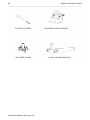
Installing the Surge Arrestor
1. Attach the unit to the mast close to the weather sensor with the
adjustable mounting clamp, see figure above.
2. Slide the steel strip beneath the latch on the back of the enclosure.
3. Wrap the steel strip around the pole mast. You may shorten the strip
to a suitable length.
4. Loosen the fastener by backing up the screw half way.
5. Attach the steel strip ends to the fastener by latching the fastener to a
hole on the strip and folding it over.
6. Tighten the fastener’s screw in order to secure the unit to the pole.
7. Ground the unit using an AWG 6 (16 mm2) copper wire.
Columbia Weather Systems, Inc.
Magellan Weather Station
31
________________________________________________________________________
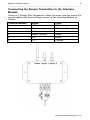
Connecting the Sensor Transmitter to the Interface
Module
Using a #1 Straight Slot screwdriver, attach the wires from the end of the
sensor cable to the terminal block screws on the Interface Module as
follows:
Terminal Number
1
2
3
4
5
6
Signal
+12 V
Ground
No Connection
Signal Ground
RX
TX
Color
RED
White and Bare
Green
Black
Orange
Columbia Weather Systems, Inc.
32
Magellan Weather Station
________________________________________________________________________
Optional Sensor Mounting Hardware
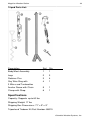
Telescoping Tripod and Tiedown Kit
The tripod is designed to provide up to 10 feet of stable, secure support
for your meteorological sensors.
Constructed from welded anodized aluminum for appearance and
longevity, the 15-pound tripod can easily support up to 60 pounds of
equipment. An optional tie-down kit allows for additional security in highwind areas.
To install, insert the legs into the main body and secure with stainless
steel retainer pins. Extend the mast to the desired height and insert
another retainer pin. Install the guy wires to complete the set-up.
Columbia Weather Systems, Inc.
Magellan Weather Station
33
________________________________________________________________________
Tripod Parts List:
Description
Ref. Qty.
Body/Mast Assembly
1
1
Legs
2
3
Retainer Pins
3
4
Guy Wire Ring with
3 Wires and Turnbuckles
4
1
Anchor Screw with Chain
5
1
Clamp with Strap
6
1
Specifications
Capacity: Supports up to 60 lbs.
Shipping Weight: 17 lbs
Shipping Box Dimensions: 71" x 9" x 9"
Tripod and Tiedown Kit Part Number: 88019
Columbia Weather Systems, Inc.
34
Magellan Weather Station
________________________________________________________________________
Sensor Mast
10-foot steel mast available for use with Roof Mount Hardware Kit (Part
No. 88002) or Wall Mount Kit (Part No.88003).
Roof Mounting
The Roof Mounting Kit (Cat. No. 88002) is suitable for both a slanted and
flat roof installation. The figure and table below illustrates and describes
the individual parts.
Description
Ref.
Qty.
Part No.
Steel mast, 10 ft.
1
1
88005
Universal Mast Anchor
2
1
88010
Lag Screw, Roof Mast Mount
3
4
88030
Guy Wire Clamp, 1/8"
4
1
88070
Steel Guy Wire, Galvanized
6
50ft.
88080
Eye Bolt Wood Screws, 1/4" x 3"
7
4
88090
3
88100
1/4" x 2 1/4" (for comp. roofs)
Turnbuckles, 6" open x 4" closed (not shown)
Columbia Weather Systems, Inc.
Magellan Weather Station
35
________________________________________________________________________
Wall Mounting
The figure and table below illustrates and describes the individual parts
in the Wall Mounting Kit (Part No. 88003). Individual parts are also
available.
Description
Ref. Qty.
Part No.
Mast, 10 ft.
1
1
88005
4" Wall Mount Bracket
9
2
88120
Lag Screw
3
4
88030
Columbia Weather Systems, Inc.
36
Magellan Weather Station
________________________________________________________________________
Columbia Weather Systems, Inc.
Magellan Weather Station
37
________________________________________________________________________
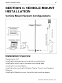
SECTION 4: VEHICLE MOUNT
INSTALLATION
Vehicle Mount System Configurations
Installation Overview
Unpacking the Unit
Installing the telescoping mast and truck-mount brackets
Installing the vehicle mount connector and routing cable
Installing the Interface Module
Installing and connecting the Weather Display Console and Computer
Software
Installing the Magellan sensor transmitter and mounting adapter
Columbia Weather Systems, Inc.
38
Magellan Weather Station
________________________________________________________________________
Unpacking the Unit
Unpack the Magellan weather station and verify that all parts are
included.
1. Standard system includes:
Magellan Sensor Transmitter
15 ft external sensor cable and male sensor connector (plus
additional cable lengths, if ordered)
50 ft internal cable with vehicle mount female sensor
connector (plus additional cable lengths, if ordered) and allweather connector cap
Interface Module with power supply
(2) 3-positon terminal block connectors
6-foot RS-232 cable (plus additional cable lengths, if
ordered)
9 ft telescoping mast with vehicle-mount brackets
Mast extension sleeve adapter
User Manual
2. Weather Display Console (Optional)
Display Console
Power supply
6-foot RS-232 cable (plus additional cable lengths, if
ordered)
User Manual
3. WeatherMaster Software, with User Manual (Optional)
Inspect all system components for obvious shipping damage (Refer to
“Important Notice: Shipping Damage” in case of damage).
Save the shipping carton and packing material in case the unit needs to
be returned to the factory. If the system does not operate or calibrate
properly, see Maintenance and Troubleshooting sections, for further
instructions.
Columbia Weather Systems, Inc.
Magellan Weather Station
39
________________________________________________________________________
Installing the telescoping mast and
vehicle-mount brackets
1. Select a location on the vehicle where the Magellan sensor mast will
be installed.
2. Three mounting brackets are included with the mast. The mounting
base plate and a spring-loaded securing mounting bracket will be
permanently mounted to the vehicle for quick and easy set up. The
third bracket is attached to the mast and mates with a slot on the
spring-loaded mounting bracket. This bracket may be loosened and
re-positioned on the mast to fit the installation scheme and mounting
bracket positioning. A spacer for the spring-loaded bracket is
provided to insure that the mast is 90° vertical.
3. Ensure the vehicle-mount sensor connector is in close proximity to
the mast’s mounting bracket location (refer to the vehicle-mount
sensor connector section below). Mark and drill the appropriate
mounting bracket holes. Be sure to allow for sufficient structural
backing, to adequately support the mast and sensor.
4. External sensor cabling is intended to hang freely along the side of
the mast. This assures the mast’s easy extension and retraction
without pinching, crimping, or cutting the sensor cable. Users may
tie-wrap the cable to the lower portion of the mast. The external
sensor cable has a male connector that couples to the vehicle-mount
female connector on the side of the vehicle.
5. To extend the mast, locate the large textured locking ring at the top
of the nested mast. This ring loosens and tightens the mast
extension. A counter-clockwise rotation loosens the ring and allows
the mast to be fully extended. Clockwise ring rotation tightens the
extension in place.
Columbia Weather Systems, Inc.
40
Magellan Weather Station
________________________________________________________________________
Installing the vehicle mount sensor
connector and routing cable
1. To install the female vehicle-mount sensor connector, drill a ¾” hole
in close proximity to the sensor mast mounting bracket installation. A
recommended location is near the mast’s lower base bracket.
2. Drill four small pilot holes for the mounting screws.
3. Run 50-ft cable through the hole and route to the Interface Module
location.
4. Connect the cable to the 3-position connectors, as listed in the chart
below.
5. Affix the connector with mounting screws on the external side of the
vehicle and ensure the associated all-weather connector cap is
securely attached.
Columbia Weather Systems, Inc.
Magellan Weather Station
41
________________________________________________________________________
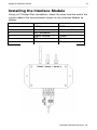
Installing the Interface Module
Using a #1 Straight Slot screwdriver, attach the wires from the end of the
sensor cable to the terminal block screws on the Interface Module as
follows:
Terminal Number
1
2
3
4
5
6
Signal
+12 V
Ground
No Connection
Signal Ground
RX
TX
Color
RED
White and Bare
Green
Black
Orange
Columbia Weather Systems, Inc.
42
Magellan Weather Station
________________________________________________________________________
Connecting the Weather Display Console
and Computer
Connect the Weather Display Console to the Interface Module using the
RJ-11 cable. The Display Console can be connected to either serial port
1 or 2.
Connect the Interface Module to the computer using the RJ-11 and DB-9
connector (RS-232 Interface). The computer can be connected to either
serial port 1 or 2. On the computer end, the DB-9 connector is plugged
into the computer serial port (normally COM port 1). If the computer does
not have a serial port, then a USB to Serial Port converter is required.
Columbia Weather Systems, Inc.
Magellan Weather Station
43
________________________________________________________________________
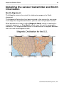
Installing the sensor transmitter and North
Orientation
North Alignment
The Magellan sensor has a built-in electronic compass for North
alignment.
The Magnetic Declination has been entered in the sensor for your area.
To change the magnetic declination, please see the Operation section.
Wind direction can refer to either Magnetic North, which is read with a
magnetic compass, or True North, which uses the earth’s geographic
meridians. The magnetic declination is the difference in degrees between
the true north and magnetic north.
Columbia Weather Systems, Inc.
44
Magellan Weather Station
________________________________________________________________________
Columbia Weather Systems, Inc.
Magellan Weather Station
45
________________________________________________________________________
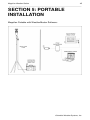
SECTION 5: PORTABLE
INSTALLATION
Magellan Portable with WeatherMaster Software:
Columbia Weather Systems, Inc.
46
Magellan Weather Station
________________________________________________________________________
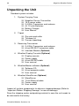
Unpacking the Unit
Standard system includes:
1. System Carrying Case
Magellan Sensor Transmitter
15 ft sensor cable
2.4 GHz Transceiver and antenna
(2) 12 volts Batteries
Battery Charger
User Manual
2. Tripod
Guy wire and collar
Tie-down kit
Canvas tripod bag
3. Receiving Transceiver
2.4 GHz Transceiver and antenna
6-foot RS-232 Transceiver cable
Interface Module (Optional)
4. Weather Display Console (Optional)
Display console
Power supply
6-foot RS-232 cable
User manual
5. WeatherMaster software (Optional)
Software CD
6-foot computer cable
User manual
6. Weather MicroServer (Optional)
MicroServer
7-foot Ethernet cable
Power supply
User manual
Inspect all system components for obvious shipping damage (Refer to
“Important Notice: Shipping Damage” in case of damage).
Save the shipping carton and packing material in case the unit needs to
be returned to the factory.
Columbia Weather Systems, Inc.
Magellan Weather Station
47
________________________________________________________________________
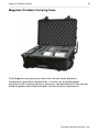
Magellan Portable Carrying Case
The Magellan carrying case stores the sensor head, batteries,
transceivers and other accessories. It serves as a weatherproof
enclosure with a wiring harness, antenna, and connection to the sensor
head for power and communication via the wireless transceiver.
Columbia Weather Systems, Inc.
48
Magellan Weather Station
________________________________________________________________________
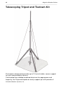
Telescoping Tripod and Tiedown Kit
The tripod is designed to provide up to 10 feet of stable, secure support
for your meteorological sensors.
Constructed from welded anodized aluminum for appearance and
longevity, the 15-pound tripod can easily support up to 60 pounds of
Columbia Weather Systems, Inc.
Magellan Weather Station
49
________________________________________________________________________
equipment. An optional tie-down kit allows for additional security in highwind areas.
To install, insert the legs into the main body secure with stainless steel
retainer pins. Extend the mast to the desired height and insert another
retainer pin. Install the guy wires to complete the set-up.
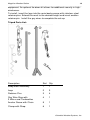
Tripod Parts List:
Description
Ref. Qty.
Body/Mast Assembly
1
1
Legs
2
3
Retainer Pins
3
4
Guy Wire Ring with
3 Wires and Turnbuckles
4
1
Anchor Screw with Chain
5
1
Clamp with Strap
6
1
Columbia Weather Systems, Inc.
50
Magellan Weather Station
________________________________________________________________________
Specifications
Capacity: Supports up to 60 lbs.
Shipping Weight: 17 lbs
Shipping Box Dimensions: 71" x 9" x 9"
Tripod and Tiedown Kit Part Number: 88019
Columbia Weather Systems, Inc.
Magellan Weather Station
51
________________________________________________________________________
RS-232 Interface Module
The RS-232 Interface Module connects up to four devices to the wireless
transceiver, such as computers, display consoles and other such
devices.
Columbia Weather Systems, Inc.
52
Magellan Weather Station
________________________________________________________________________
Set Up Instructions
Site Selection:
1. Upon arrival at the deployment site, determine a suitable location
where the Magellan mast may be set up away from physical
obstructions and heavy foot traffic. Because of the wireless
transceivers, the telescoping tripod and sensors may be located
as far as 1-mile (Line of Sight - LOS) away from where the
weather data is viewed.
2. Site location should be away from trees, buildings or other
obstructions that will alter accurate wind direction and speedreadings.
3. Screw the grounding/tie-down auger into the ground at the
center of the placement until the auger portion is adequately
secured.
4. If the site selection is on blacktop/pavement, use a 6” nail spike
or Rebar driven into the surface at a 45° angle. This sufficiently
secures the mast during operations.
Mast Set Up and Sensor Alignment:
1. Remove tripod components from the bag. Stand the tripod up
(without legs) so the sensor head may be attached to the mast.
2. Attach the Sensor Head to the mast.
3. Attach sensor cable by connecting the 8-pin waterproof male
connector/sensor cable to the one-foot female sensor pig-tail
waterproof connector.
4. Holding the tripod vertical, place tripod legs in their respective
slots, one leg at a time. Once the first leg is in, balance the tripod
until the other legs are inserted and the tripod is free standing.
5. With all legs in place, insert the leg locking pins. The tripod may
now be picked up and moved over the grounding stake.
6. Secure the tripod to the grounding stake using the clamp strap.
Ensure the strap is tight enough to keep the tripod in-place
during high winds.
7. Extend the mast to its fullest height and insert the locking pin.
8. If the guy wire kit is used, remove the sensor and mounting
adapter prior to mast set up and slide the guy wire ring collar
onto the mast extension, then reinstall the sensor. Anchor the
end of each guy wire to the corresponding tripod foot using the
wing nuts. Extend the mast fully and adjust the guy wires using
the turnbuckles to tighten the guy wires evenly.
Columbia Weather Systems, Inc.
Magellan Weather Station
53
________________________________________________________________________
Transportation Case and Sensor Plug-In
1. Place the Magellan transportation case at the foot of the tripod.
2. Attach the 8-inch wireless antenna to the antenna cable on the
outside of the case.
3. Plug the 8-pin Female Sensor Cable to the 8-pin male connector
on the outside of the case.
4. Ensure the red/black power cord connectors are connected to
their respective battery terminals inside the case.
5. Latch and seal the case to the internal components from the
weather elements.
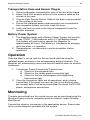
Battery Power System
1. The Magellan comes with a Battery Power System that consists
of two 12VDC, 7.5AH batteries and a 12-Volt battery charger.
One battery will continuously operate the Magellan for
approximately 60 hours. One battery is intended to be charging
while the other is in operation.
2. Swap batteries, as necessary to continue weather station
operations.
Operation
Once the Mast is set up, with the Sensor Head attached, plug the
red/black power terminals to the corresponding battery terminals. The
Magellan will automatically sense and transmit weather data via wireless
transceiver.
1. Transceiver Power/Connectivity/Transmission:
a) Check for the red power light
b) Check for the steady green connectivity light
c) Check for the one-second green pulsing/blinking
transmission light
2. Once the transceiver lights are all operational, data is being
transmitted. If the green transmission light is not blinking once
per second, data is not being transmitted. Re-check the RS-232,
power, and antenna connections.
Monitoring
The data transmitted from the remote sensor can be monitored using the
Weather Display console, computer weather software, and/or Weather
MicroServer.
Connect the wireless transceiver to the appropriate device. Please refer
to the system diagrams provided with the system.
Columbia Weather Systems, Inc.
54
Magellan Weather Station
________________________________________________________________________
Columbia Weather Systems, Inc.
Magellan Weather Station
55
________________________________________________________________________
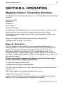
SECTION 6: OPERATION
Magellan Sensor Transmitter Interface
The Magellan sensor communicates via a serial interface at the following
settings:
Baud rate: 9600
Data bits: 8
Stop bits: 1
Parity: None
Flow control: None
On power up, the Magellan sensor automatically outputs a string of data
containing the current values of all parameters once per second.
To activate terminal mode, hit the <Enter> key three times within a two
second period.
Successful entry into terminal mode will return the prompt:
Command (HE for Help, QU to Quit):
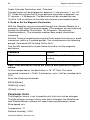
Magnetic Declination
The flux compass in the Magellan sensor provides wind direction to
Magnetic North. The sensor firmware allows the setting of a declination
angle to correct the wind direction output to True North. Once the
declination angle is set in the sensor, it is stored permanently in nonvolatile memory. The declination angle must be reset only if the system
is used in a different geographical location separated by many miles from
the original location.
Please note that the magnetic declination is set at the factory per
system, based on the shipping destination.
To reset the magnetic declination:
1. Determine the Correct Declination
Visit the following web site for help in determining the correct declination
for your site:
http://www.ngdc.noaa.gov/geomag/declination.shtml
Under Declination click “Calculate”
Under Lookup Latitude/ Longitude enter your zip code and click “Get &
Add Lat / Lon” or manually enter latitude and longitude.
Columbia Weather Systems, Inc.
56
Magellan Weather Station
________________________________________________________________________
Under Calculate Declination click “Calculate”
The declination will be displayed in degrees (º) and minutes ('), e.g. 16º
27'. Divide the minutes by 60 to get decimal remainder of degrees, e.g.
27 minutes = 0.45 degrees. The declination will be rounded up from
16.45 to 16.5 to conform to the data entry format of one decimal place.
2. Read or Set the Magnetic Declination
With the Magellan sensor connected through the Interface Module to a
computer, start HyperTerminal program. (This program can be accessed
through the Windows Start button - All Programs - Accessories Communications.) The automatic weather data output should start
streaming.
Activate Terminal mode by pressing the Enter button three times in quick
succession (within a 2-second period). You should receive the following
prompt: Command (HE for Help, QU to Quit):
Use the MD command as shown below to read or set the magnetic
declination:
Command
Result
MD<Enter>
Report Magnetic Declination
setting
MDxx.x<Enter>
Set declination to xx.x degrees
Note: West declination values are entered and reported as negative
values.
In the example above, the declination is 16° 27' East. The value
converted to decimal is 16.45. If entered as such, it will be rounded up to
16.5.
Enter the following commands:
MD16.5[Enter]
QU[Enter] to quit.
Y[Enter] to save.
Parameter Units
The Magellan sensor is set to specific units that must not be changed.
The MicroServer assumes these units and if changed, the MicroServer
and WeatherMaster software will report incorrect parameter values.
Wind speed: m/s
Temperature: °C
Relative Humidity: %RH
Columbia Weather Systems, Inc.
Magellan Weather Station
57
________________________________________________________________________
Barometric Pressure: milliBar
Columbia Weather Systems, Inc.
58
Magellan Weather Station
________________________________________________________________________
Columbia Weather Systems, Inc.
Magellan Weather Station
59
________________________________________________________________________
SECTION 7: CALIBRATION
Factory Calibration
Send the device to Columbia Weather Systems, Inc. for calibration and
adjustment, see Section 9: USER SUPPORT INFORMATION for more
information.
Temperature and Pressure Reading
Adjustments
Even though the temperature sensor is calibrated at the factory to ±0.5°
F and requires no further calibration, and similarly the pressure sensor is
calibrated to ±0.015 inches Hg, the sensors reading can be adjusted
using WeatherMaster software or the Weather Display console. Please
refer to their user manual for more information.
Columbia Weather Systems, Inc.
60
Magellan Weather Station
________________________________________________________________________
Columbia Weather Systems, Inc.
Magellan Weather Station
61
________________________________________________________________________
SECTION 8: MAINTENANCE
Because the sensor has no moving parts to wear out, periodic
maintenance is not required.
The only user repairable part is the Temperature/Relative Humidity
Sensor Module (T/RH Module) located inside the multi-plate shield.
To order the T/RH Module please contact Columbia Weather Systems
for more information.
Columbia Weather Systems, Inc.
62
Magellan Weather Station
________________________________________________________________________
Columbia Weather Systems, Inc.
Magellan Weather Station
63
________________________________________________________________________
SECTION 9: USER SUPPORT
INFORMATION
This section consists of the following items:
1. One-Year Limited Warranty: Please read this document carefully.
2. Return for Repair Procedure: This procedure is for your convenience
in the event you must return your Magellan for repair or replacement.
Follow the packing instructions carefully to protect your instrument in
transit.
Limited Warranty
Columbia Weather Systems, Inc. (CWS), warrants the Magellan Weather
Station to be free from defects in materials and/or workmanship when
operated in accordance with the manufacturer’s operating instructions,
for one (1) years from date of purchase, subject to the provisions
contained herein. CWS warranty shall extend to the original purchaser
only and shall be limited to factory repair or replacement of defective
parts.
EXCLUSIONS
Certain parts are not manufactured by CWS (i.e., certain purchased
options, etc.) and are therefore not covered by this warranty. These parts
may be covered by warranties issued by their respective manufacturers
and although CWS will not warrant these parts, CWS will act as agent for
the administration of any such independent warranties during the term of
this warranty. This warranty does not cover normal maintenance,
damage resulting from improper use or repair, or abuse by the operator.
Damage caused by lightning or other electrical discharge is specifically
excluded. This warranty extends only to repair or replacement, and shall
in no event extend to consequential damages. In the event of operator
repair or replacement, this warranty shall cover neither the advisability of
the repair undertaken, nor the sufficiency of the repair itself.
THIS DOCUMENT REFLECTS THE ENTIRE AND EXCLUSIVE
UNDERSTANDING OF THE PARTIES, AND EXCEPT AS OTHERWISE
PROVIDED HEREIN, ALL OTHER WARRANTIES, EXPRESS OR
IMPLIED, PARTICULARLY THE WARRANTIES OF MERCHANT
ABILITY AND/OR FITNESS FOR A PARTICULAR PURPOSE ARE
EXCLUDED.
Columbia Weather Systems, Inc.
64
Magellan Weather Station
________________________________________________________________________
This warranty gives you specific legal rights, and you may also have
other rights which vary from state to state.
Return for Repair Procedure
1.
In the event of defects or damage to your unit, first call the
Service Department Monday through Friday, 8:30 am to 4:00 pm
PST, (503) 629-0887 to determine the advisability of factory
repair. The Service Department will issue an RMA number
(Return Merchandise Authorization) to help us identify the
package when received. Please write that number on the outside
of the box.
2.
In the event factory service is required, return your Magellan
Weather Station as follows:
A.
Packing
Wrap the Sensor Transmitter in a plastic bag first.
Pack in original shipping carton or a sturdy oversized
carton.
Use plenty of packing material.
B.
Include:
A brief description of the problem with all known
symptoms.
Your telephone number.
Your return street shipping address (UPS will not deliver
to a P.O. box).
Write the RMA number on the outside of the box.
C.
Shipping
Send freight prepaid (UPS recommended).
Insurance is recommended. (The factory can provide the
current replacement value of the item being shipped for
insurance purposes.)
D.
Send to:
Columbia Weather Systems, Inc.
5285 NE Elam Young Parkway, Suite C100
Hillsboro, Oregon 97124
E.
3.
C.O.D. shipments will not be accepted.
If your unit is under warranty, after repair or replacement has
been completed, it will be returned by a carrier and method
Columbia Weather Systems, Inc.
Magellan Weather Station
65
________________________________________________________________________
chosen by Columbia Weather, Inc. to any destination within the
continental U.S.A. If you desire some other specific form of
conveyance or if you are located beyond these borders, then you
must bear the additional cost of return shipment.
4.
If your unit is not under warranty, we will call you with an
estimate of the charges. If approved, your repaired unit will be
returned after all charges, including parts, labor and return
shipping and handling, have been paid. If not approved, your unit
will be returned as is via UPS COD for the amount of the UPS
COD freight charges.
Columbia Weather Systems, Inc.
66
Magellan Weather Station
________________________________________________________________________
Columbia Weather Systems, Inc.
Magellan Weather Station
67
________________________________________________________________________
Reference
Glossary
Aspirating Radiation Shield
A device used to shield a sensor such as a temperature probe from
direct and indirect radiation and rain while providing access for
ventilation.
Barometric Pressure
The pressure exerted by the atmosphere as a consequence of
gravitational attraction exerted upon the “column” of air lying directly
above the point in question.
Celsius Temperature Scale
A temperature scale with the ice point at 0 degrees and the boiling point
of water at 100 degrees.
Dew Point
The temperature to which a given parcel of air must be cooled at
constant pressure and constant water-vapor content in order for
saturation to occur. When this temperature is below 0°C, it is sometimes
called the frost point.
Fahrenheit Temperature Scale
A temperature scale with the ice point at 32 degrees and the boiling point
of water at 212 degrees.
Heat Index
The heat index or apparent temperature is a measure of discomfort due
to the combination of heat and high humidity. It was developed in 1979
and is based on studies of evaporative skin cooling for combinations of
temperature and humidity.
Relative Humidity
Popularly called humidity. The ratio of the actual vapor pressure of the
air to the saturation vapor pressure.
Columbia Weather Systems, Inc.
68
Magellan Weather Station
________________________________________________________________________
Sea Level Pressure
The atmospheric pressure at mean sea level, either directly measured
or, most commonly, empirically determined from the observed station
pressure.
In regions where the earth’s surface pressure is above sea level, it is
standard observational practice to reduce the observed surface pressure
to the value that would exist at a point at sea level directly below.
Wind Chill
That part of the total cooling of a body caused by air motion.
Columbia Weather Systems, Inc.
Magellan Weather Station
69
________________________________________________________________________
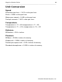
Unit Conversion
Speed
Kilometers per hour = 1.610 x miles per hour
Knots = 0.869 x miles per hour
Meters per second = 0.448 x miles per hour
Feet per second = 1.467 x miles per hour
Temperature
Temperature in °C = 5/9 (temperature in °F - 32)
Temperature in °F = (1.8 x temperature in °C) + 32
Distance
Millimeters = 25.4 x inches
Pressure
Millibars = 33.86 x inches of mercury
Kilopascals = 3.386 x inches of mercury
Pounds per square inch = 0.49 x inches of mercury
Standard atmospheres = 0.0334 x inches of mercury
Columbia Weather Systems, Inc.
70
Magellan Weather Station
________________________________________________________________________
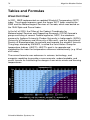
Tables and Formulas
Wind Chill Chart
In 2001, NWS implemented an updated Wind chill Temperature (WCT)
index. The change improves upon the former WCT Index used by the
NWS and the Meteorological Services of Canada, which was based on
the 1945 Siple and Passel Index.
In the fall of 2000, the Office of the Federal Coordinator for
Meteorological Services and Supporting Research (OFCM) formed a
group consisting of several Federal agencies, MSC, the academic
community (Indiana University-Purdue University in Indianapolis (IUPUI),
University of Delaware and University of Missouri), and the International
Society of Biometeorology to evaluate and improve the windchill formula.
The group, chaired by the NWS, is called the Joint Action Group for
temperature Indices (JAG/TI). JAG/TI's goal is to upgrade and
standardize the index for temperature extremes internationally (e.g. Wind
chill Index).
The current formula uses advances in science, technology, and
computer modeling to provide a more accurate, understandable, and
useful formula for calculating the dangers from winter winds and freezing
temperatures.
Columbia Weather Systems, Inc.
Magellan Weather Station
71
________________________________________________________________________
Wind Chill Equation
WC = 35.74 + 0.6215 T -35.75(V0.16) + 0.4275 T(V0.16)
Where:
WC = wind chill temperature in °F
V = wind velocity in mph
T = air temperature in °F
Note: Wind chill Temperature is only defined for temperatures at or
below 50 degrees F and wind speeds above 3 mph.
Columbia Weather Systems, Inc.
72
Magellan Weather Station
________________________________________________________________________
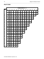
Heat Index
Temperature in °F
70
75
80
85
90
95
100 105 110 115 120 125 130 135
0
64
66
73
78
83
87
91
95
99
5
64
69
74
79
84
88
93
97
102 107 111 116 122 126
10
65
70
75
80
85
90
95
100 105 111 116 123 131
15
65
71
76
81
86
91
97
102 108 115 123 131
20
66
72
77
82
87
93
99
105 112 120 130 141
25
66
72
77
83
88
94
101 109 117 127 139
30
67
73
78
84
90
96
104 113 123 135 148
35
67
73
79
85
91
98
107 118 130 143
40
68
74
79
86
93
101 110 123 137 151
45
68
74
80
87
95
104 115 129 143
50
69
75
81
88
96
107 120 135 150
55
69
75
81
89
98
110 126 142
60
70
76
82
90
100 114 132 149
65
70
76
83
91
102 119 138
70
70
77
84
93
106 124 144
75
70
77
85
95
109 130 150
80
71
78
86
97
113 136
85
71
78
87
99
117 140
90
71
79
88
102 122 150
95
71
79
89
105 126
100
72
80
90
108 131
RH
Columbia Weather Systems, Inc.
103 107 111 117 120
Magellan Weather Station
73
________________________________________________________________________
Dew Point
B = (ln (RH/100) + ((17.2694*T) / (238.3+T))) / 17.2694
Dew Point in °C = (238.3 * B) / (1-B)
Where:
RH = Relative Humidity
T = Temperature in °C
Ln = Natural logarithm
Columbia Weather Systems, Inc.
74
Magellan Weather Station
________________________________________________________________________
Columbia Weather Systems, Inc.
5285 NE Elam Young Parkway, Suite C100
Hillsboro, OR 97124
Telephone
(503) 629-0887
Fax
(503) 629-0898
Web Site
http://www.columbiaweather.com
Email
[email protected]
Catalog Number: 81656
Version 2.03
Printed in U.S.A.
Columbia Weather Systems, Inc.