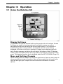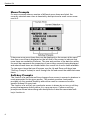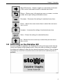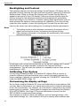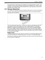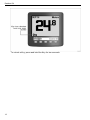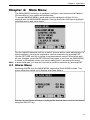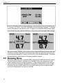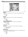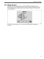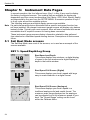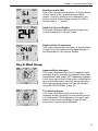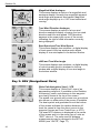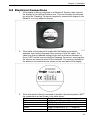
1
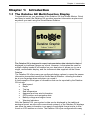
Dataline GX
User Manual
For Software Version 1.04
Stowe Marine Ltd.
235 Bentley Way
LYMINGTON
SO41 8JW
England
www.stowemarine.com
© Stowe Marine Ltd. 2008
The copyright of this manual is the property of Stowe Marine Ltd.
Product liability and safety warnings
Product liability
Stowe Marine Ltd. accepts no responsibility for the use and/or operation of this
equipment. It is the user’s responsibility to ensure that under all circumstances the
equipment is used for the purposes for which it has been designed.
Warning – electrical hazard
This equipment uses high voltage electrical power. Contact with high voltages may
result in injury and/or loss of life.
Warning - calibration
The safe operation of this equipment is dependent on accurate and correct calibration.
Incorrect calibration of this equipment may lead to false and inaccurate navigational
readings placing the vessel into danger.
Caution
The use of solvent based or chemical cleaners on Dataline will result in damage and
invalidate your warranty.
Caution
Dataline contains no user-serviceable parts. Repairs should only be made by an
authorised service centre. Unauthorised repairs or modifications may invalidate the
warranty.
EMC Directive 89/336/EEC
This product has been designed to be compliant with the above
Directive. Maximum performance, and compliance with the EMC
Directive, can only be ensured by correct installation. It is strongly
recommended that the installation conforms to the following
standards:
Small Craft – Electrical Systems:
A.
B.
ISO 10133 –Extra Low-Voltage DC Installations
ISO 13297 –Alternating Current Installations
ISO = International Standards Organization
Trademarks
All rights reserved. No part of this manual may be reproduced or transmitted in any
form or by any means including photocopying and recording, for any purpose without
the express written permission of Stowe Marine Ltd.
Information in this document is subject to change without notice. Stowe Marine Ltd.
reserves the right to change or improve its products and to make changes in the
content without obligation to notify any person or organisation of such changes.
Stowe, Dataline and Dataline GX are all trademarks of Stowe Marine Ltd. and may not
be used without the express permission of Stowe Marine Ltd.
Stowe is a registered trademark of Stowe Marine Ltd.
Dataline is a registered trademark of Stowe Marine Ltd.
NMEA is a registered trademark of the National Marine Electronics Association.
NMEA 2000 is a registered trademark of the National Marine Electronics Association.
The information contained in this manual is believed to be accurate at the time of going
to print but no responsibility, direct or consequential, can be accepted for damage
resulting from the use of this information. The manufacturers reserve the right to make
changes, without notice, to any of its products.
© Stowe Marine Ltd. 2008
About Stowe Marine Limited
Thank you for choosing Stowe Marine, a trusted name in marine electronics. Stowe
Marine has built its reputation by designing and manufacturing top-quality, thoroughly
reliable marine equipment. Your Stowe Marine Dataline system is designed for troublefree use in even the harshest marine environment.
About this manual
We encourage you to read this manual carefully in order to get full benefit from all the
features and uses of your Stowe Marine product. Also, please register your purchase
by filling out the warranty registration card.
Throughout this manual, Notes, Warnings and Cautions are used to alert the user or
installer to special instructions concerning a particular service or operation that may be
hazardous if performed incorrectly or carelessly.
Observe these alerts carefully!
Warning
This device should not be used as a navigational aid to prevent collision, grounding,
boat damage, or personal injury. When the boat is moving, water depth may change
too quickly to allow time for you to react. Always operate the boat at very slow speeds if
you suspect shallow water or submerged objects.
Warning
Disassembly and repair of this electronic unit should only be performed by authorised
service personnel. Any modification of the serial number or attempt to repair the original
equipment or accessories by unauthorised individuals will invalidate the warranty.
Handling and/or opening this unit may result in exposure to lead, in the form of solder.
Warning
This product contains lead, a chemical known to the State of California to cause cancer
and birth defects and other reproductive harm.
Dataline GX
Contents
CHAPTER 1:
1.1
THE DATALINE GX MULTI-FUNCTION DISPLAY ............................................ 3
CHAPTER 2:
2.1
2.2
3.2
3.3
4.4
4.5
OPERATION........................................................................... 7
USING THE DATALINE GX .......................................................................... 7
Display Soft-keys.............................................................................. 7
Menu and Soft-key Prompts ............................................................. 7
Menu Prompts .................................................................................. 8
Soft-key Prompts .............................................................................. 8
SWITCHING ON THE DATALINE GX .............................................................. 9
Backlighting and Contrast .............................................................. 10
Calibrating Your System ................................................................ 10
Customising the display settings .................................................... 10
SCREEN SELECTION ................................................................................ 11
Page Lock ...................................................................................... 11
CHAPTER 4:
4.1
4.2
4.3
QUICK START GUIDE ........................................................... 5
BASIC SETUP ............................................................................................ 5
DATA PAGE FLOWCHART ........................................................................... 6
CHAPTER 3:
3.1
INTRODUCTION .................................................................... 3
MAIN MENU ......................................................................... 13
ALARM MENU .......................................................................................... 13
DAMPING MENU ...................................................................................... 14
SETUP MENU .......................................................................................... 15
Beeper ............................................................................................ 15
Language ....................................................................................... 15
Mode .............................................................................................. 16
Demo .............................................................................................. 16
Reset All ......................................................................................... 17
UNITS MENU ........................................................................................... 17
Speed ............................................................................................. 18
Depth .............................................................................................. 18
Temp (Temperature) ...................................................................... 18
Distance ......................................................................................... 18
Wind Speed .................................................................................... 18
Bearing ........................................................................................... 19
CALIBRATE MENU ................................................................................... 19
Speed ............................................................................................. 20
Speed Range ................................................................................. 21
Depth Offset ................................................................................... 21
Mast Align....................................................................................... 22
1
Dataline GX
4.6
ABOUT SCREEN ...................................................................................... 23
CHAPTER 5:
5.1
5.2
SAIL BOAT MODE SCREENS ..................................................................... 24
KEY 1: Speed/Depth/Log Group .................................................... 24
Key 2: Wind Group ......................................................................... 25
Key 3: NAV (Navigational Data) ..................................................... 26
Key 4: Statistics and Engine Data .................................................. 28
OTHER SCREENS .................................................................................... 28
CHAPTER 6:
6.1
6.2
6.3
6.4
6.5
7.2
7.3
TECHNICAL INFORMATION ............................................... 35
SPECIFICATIONS ...................................................................................... 35
Power ............................................................................................. 35
Display Unit .................................................................................... 35
Communication............................................................................... 35
Environmental................................................................................. 35
TROUBLESHOOTING ................................................................................. 36
Visual Inspection ............................................................................ 36
MAINTENANCE......................................................................................... 36
CHAPTER 8:
8.1
8.2
INSTALLATION .................................................................... 29
BEFORE YOU BEGIN ................................................................................ 29
What you’ll need ............................................................................. 29
MOUNTING THE DATALINE GX .................................................................. 29
Bulkhead Mounting ......................................................................... 29
FIXING TEMPLATE.................................................................................... 31
MOUNTING THE DATALINE GX IN A BULKHEAD .......................................... 32
ELECTRICAL CONNECTIONS ..................................................................... 33
Power Connections ........................................................................ 34
CHAPTER 7:
7.1
INSTRUMENT DATA PAGES .............................................. 24
CUSTOMER SUPPORT ....................................................... 37
TWO YEAR WARRANTY ............................................................................ 37
CUSTOMER SERVICE ............................................................................... 38
CHAPTER 9:
GLOSSARY .......................................................................... 43
CHAPTER 10:
INDEX ................................................................................... 45
2
Chapter 1 Introduction
Chapter 1:
Introduction
1.1 The Dataline GX Multi-Function Display
Congratulations on your purchase of the Dataline GX from Stowe Marine. Quick
and easy to install, the Dataline GX provides important information anytime and
anywhere you want using the Stowe Marine Dataline.
The Dataline GX is designed to report instrumentation data identical to that
displayed by traditional gauges on a boat. However, it eliminates the need for
multiple display heads to be installed on your boat since it allows you to use a
single, customisable display, and the instrument data supplied via the Stowe
Dataline.
The Dataline GX offers many pre-configured display options to repeat the sensor
information transmitted across the Stowe Marine Dataline - allowing the data to
be at your fingertips when and where you need it.
A few examples of the types of information that can be reported by the Dataline
GX include:
•
Boat speed
•
Depth
•
Trip log
•
Sea temperature
•
Apparent and true wind information
•
GPS position and navigation data
•
Battery voltage and engine hours
•
Warning Indicators
With the Dataline GX, your system’s data can be displayed in the traditional
analogue format, as seen with conventional systems, or the Dataline GX displays
can show the same information in an easy-to-read digital format similar to that
found on LCD watches or clocks. The Dataline GX is pre-configured with many
3
Dataline GX
different screen configurations to repeat the data available via the system
Dataline.
Note If a particular sensing device associated with a specific instrument function has
not been installed, that relevant function will display a series of dashes “- - -“
instead of the data.
4
Chapter 2 Quick Start Guide
Chapter 2:
Quick Start Guide
2.1 Basic Setup
The Dataline GX has been designed for use with both sail and powered craft. The
pre-configured screens accessed via the four left-most buttons (Hot Keys) differ
slightly, dependent upon which mode has been selected by the user. These
choices are as follows:
•
Sail
•
Motor
•
GPS
•
Wind
•
Speed
•
Depth
The four hot keys provide you with a quick and easy way to display essential data
at the press of a button, without the need to scroll through endless menus. By
selecting the most appropriate mode for your needs, you will ensure that the
display of inappropriate data is minimised. Refer to the instructions on Page 16
for configuration information.
Other examples of basic setup functions are the Language settings, and the units
used for the display of boat speed and wind speed. These settings are found
under the MAIN MENU by pressing and holding the rightmost key (see
“Operation” on next page) and then checking the relevant menus.
5
Dataline GX
2.2 Data Page Flowchart
6
Chapter 3 Operation
Chapter 3:
Operation
3.1 Using the Dataline GX
Display Soft-keys
The Dataline GX has five Screen Soft-keys that control all unit functions. Screen
Soft-keys are used for choosing analogue and digital screens, as well as
navigating through and choosing the various menu options. The functions of
these five keys are context-sensitive, and depend upon the screen being
displayed at the time a soft-key is pressed. A popup menu showing each softkey’s function appears just above the soft-key at the bottom of the LCD display.
There is also an audible “beep” when any button is pressed to confirm the button
press. This beeping function can be disabled within the SETUP MENU (Page 15).
Menu and Soft-key Prompts
When working with the Dataline GX functions and menus, there are many ways to
choose options and enter information. Many of the screens that will require your
input will also give you Prompts on how to enter the information or choose
options.
7
Dataline GX
Menu Prompts
On menu screens where a number of different menu items are listed, the
currently selected menu item is denoted by bold print and a small cursor arrow
next to it.
If there are more menu items than can be displayed on the screen at the same
time then a scroll bar is displayed on the left side of the screen to indicate that
more items are available off-screen. The size and position of the dark box within
the scroll bar represents the proportion of menu items currently being displayed
and where these items are located within the overall list of menu items available.
To view menu items that are off-screen, use the Up and Down soft-keys (see
“Soft-key Prompts” below) to scroll through the list and reveal the additional menu
items.
Soft-key Prompts
The function of a particular soft-key changes from screen to screen to whatever is
most appropriate for the given screen. This context sensitive functionality
provides you the greatest flexibility without the need for numerous functionspecific buttons for every task.
The function of a soft-key on a particular screen is shown by an icon or soft-key
prompt that appears directly above it in a pop-up menu. Common soft-key
prompts are shown below along with descriptions of what the associated softkey’s function is.
8
Chapter 3 Operation
Adjust/Customise – Adjusts, toggles or customises an element
of the current instrument screen or selected menu item.
Return – Returns you to the previous menu or screen, or enters
a data value upon exiting a calibration screen.
Decrease – Decreases the setting of a selected menu item.
Down – Moves the cursor arrow down to select the next menu
item in a list
Increase – Increases the setting of a selected menu item.
Enter – Stores the setting of a selected function.
Up – Moves the cursor arrow up to select the previous menu
item in a list.
3.2 Switching on the Dataline GX
As soon as power is applied to the Dataline GX it will go through a short start-up
routine and display a logo splash screen. When the start-up routine is complete
the display will change to show the last viewed instrument screen. If the unit does
not power-up, ensure all connections are correct and secure and that power is
available.
9
Dataline GX
Backlighting and Contrast
The backlight intensity and contrast settings for the Dataline GX display can be
adjusted by briefly pressing the right-most soft-key whilst viewing any instrument
display screen. Doing so causes the Lighting and Contrast Pop-up Menu to
appear at the bottom of the LCD display. Press the soft-key directly below the
soft-key prompt for the adjustment desired and that display will immediately
adjust according to your selection. Continue making these adjustments until you
have achieved the optimum viewing settings for readability. Press the soft-key
under the return symbol to leave the Lighting and Contrast Pop-up Menu and
return to the screen you were viewing prior to making the display adjustments.
Notes
1.
2.
The lighting levels on other displays connected to the system will not
adjust until exiting this screen, by pressing the Return soft-key.
Other displays connected to the system are unaffected by the contrast
adjustment function.
If brightness and contrast are accidentally set so that the Lighting and Contrast
Pop-up Menu is no longer readable, press the four leftmost soft-keys
simultaneously. This will reset the contrast to a readable medium value and the
backlighting to 100%.
Calibrating Your System
For accuracy of displayed data, the Dataline GX display offers a number of
powerful calibration routines that allow you to quickly and easily calibrate the
sensor readings. Calibrate your system following the “CALIBRATE” instructions
under the MAIN MENU (Page 13).
Customising the display settings
As you begin using the Dataline GX, there will doubtlessly be some features that
you may want to customise to your needs and preferences to take full advantage
of the unit’s functionality. For example, you may want to change the units used to
denote speed or distance. These types of changes are made using the Dataline
GX’s SETUP MENU. See Page 15 for more information on how to use the
SETUP MENU to customise these settings.
Any changes you make to these user settings, such as lighting/contrast, units
used, alarm settings, etc., are retained in the unit’s memory after shutdown and
10
Chapter 3 Operation
are automatically restored when the Dataline GX is powered back on again. This
includes any user setting changes made during the Dataline GX’s “Demo” mode.
Likewise, any settings saved in the Dataline GX’s normal operation mode will be
available in the “Demo” mode.
3.3 Screen Selection
The Dataline GX displays instrument data and information on screens selected by
the user. These screens are accessed via the five screen soft-keys positioned
just below the LCD display.
The four leftmost soft-keys (Key 1 to Key 4) are factory configured and will take
you directly to the pre-set screens with only a single keypress. The screens
available for display are dependent upon the current mode setting (Sail, Motor,
GPS, Wind, Speed, Depth) as determined by the user from the SETUP MENU.
Successive presses of each of these keys will cycle around the available options.
Further details concerning the specific screens available can be found in Chapter
5, Instrument Data Pages.
Page Lock
The Page Lock facility allows a key to be locked to one particular display screen,
so that it may easily be recalled at the push of a button. To activate the Page
Lock feature, simply press and hold the Key you wish to lock for two seconds until
the Key symbol is displayed.
11
Dataline GX
To unlock a Key, press and hold the Key for two seconds.
12
Chapter 4 Main Menu
Chapter 4:
Main Menu
The MAIN MENU allows you to calibrate, configure, and customise the Dataline
GX according to your needs and preferences.
To access the MAIN MENU, press and hold the rightmost soft-key for five
seconds until the MAIN MENU appears. Use Up and Down soft-keys to highlight
individual menus and menu items.
Use the Adjust/Customise soft-key to select choices and/or make adjustments. In
some instances, you may be required to confirm a selection by pressing ENT.
Use the RETURN soft-key to return to previous/parent menus. When done with
all your changes, press the RETURN soft-key again to exit from the MAIN MENU
to return to the display screen you were viewing prior to accessing the menu.
Note In some instances, you may be required to confirm a selection by pressing ENT.
4.1 Alarm Menu
Selecting ALARM from the MAIN MENU selects the Alarm MENU screen. This
menu allows the setting up of Shallow and Deep Alarms.
Use the Up and Down soft-keys to highlight the desired alarm function and select
using the ADJUST key.
13
Dataline GX
Use the Decrease and Increase soft-keys to set the alarm level in increments of
0.1 meters, (0.3 feet). Press RETURN when finished making changes. To disable
either of the alarms, set them to zero. The alarm is activated whenever the depth
drops below the user adjusted Shallow or above the user adjusted Deep settings.
The active alarm ‘flashes’ in the centre of the screen and the buzzer sounds until
the alarm is either temporarily cancelled by pressing the right hand button or the
current depth changes to a value outside of the user adjusted settings. The alarm
will automatically sound again if the alarm condition returns.
4.2 Damping Menu
Selecting DAMPING from the MAIN MENU selects the DAMPING MENU screen.
This menu allows sensor readings to be damped if they are changing too fast,
which normally occurs in rougher weather. A higher damping value will slow the
rate at which the readings are updated or changed, making them easier to read.
However, this also means that if left on a higher setting, some measured data
may not be displayed as quickly as required.
14
Chapter 4 Main Menu
Use the Up and Down soft-keys to highlight the desired sensor reading. Use the
Decrease and Increase soft-keys to set the level of damping (0 = no damping, 9 =
maximum damping). Press RETURN when finished making all changes. The
factory default setting for all damping values is 2 seconds.
4.3 Setup Menu
Beeper
This function enables and disables the internal beeper from sounding each time a
soft-key is pressed. Audible alarm functions remain unaffected. This function will
only adjust the local unit and the setting is stored in memory through a power-off.
Use the Adjust/Customise soft-key to toggle the key press beeper’s operational
status.
Language
Selecting LANGUAGE from the SETUP MENU displays the LANGUAGE MENU
screen. This menu allows you to change the language used by all the displays in
a networked system.
15
Dataline GX
Select the desired language by using the Up, Down, and Adjust/Customise softkeys.
Mode
The Dataline GX Display has been designed for use with both sail and powered
craft. The operational functions differ slightly, depending on the choice of
operating modes. The operating modes are:
•
Sail
•
Motor
•
GPS
•
Wind
•
Speed
•
Depth
To alter the display mode, simply press the Adjust soft-key to cycle through the
available menu choices.
Demo
The Dataline GX can be configured to run an internal demonstration program,
which useful for learning the operation of the display.
16
Chapter 4 Main Menu
Reset All
This setting should be used with caution since all calibration data and user
settings will be lost.
The RESET ALL function resets all settings back to a default value.
Press OK to reset your Dataline GX or press the RETURN soft-key to cancel.
4.4 Units Menu
Selecting UNITS from the SETUP MENU produces the UNITS MENU screen.
This menu allows you to customise the types of units used in measurements and
readouts. Selected units can be metric, statute, or nautical. UNITS are global
settings on a networked system. That is, the settings for UNITS can be changed
on any Dataline GX on a network and that change will consequently be made to
all units on that network.
17
Dataline GX
Available unit options include:
Speed
The Speed setting allows the units to be selected for the displayed boat speed
readings:
•
Knots
•
MPH
•
Km/h
Depth
The Depth setting allows the units to be selected for the displayed depth
readings:
•
Metres
•
Feet
•
Fathoms
Temp (Temperature)
The Temp setting allows the units to be selected for the displayed sea
temperature readings:
•
•
°C (Celsius)
°F (Fahrenheit)
Distance
The Distance setting allows the units to be selected for the displayed Log
readings:
•
Nm (Nautical miles)
•
Miles (Statute)
•
Km
Wind Speed
The Wind Speed setting allows the units to be selected for the displayed apparent
wind speed, and true wind speed readings:
•
Knots
•
m/s
•
Beaufort
•
MPH
18
Chapter 4 Main Menu
Bearing
The Bearing setting allows the user to select the units for headings and bearings:
•
MAG (Magnetic)
•
TRUE
4.5 Calibrate Menu
Selecting CALIBRATE MENU from the MAIN MENU produces the CALIBRATE
MENU screen. This menu allows you to fine tune and calibrate some of your
sensors to ensure accurate data on-screen.
Descriptions and instructions for each of the functions available under the
CALIBRATE MENU are listed below.
19
Dataline GX
Speed
The SPEED option alters the boat speed transducer readings in 2.5% increments
and decrements from the factory default setting of 0.0%.
For convenience, real-time SOG (Speed Over Ground) data from a position fixer
is displayed on-screen to simplify the boat speed calibration. This information can
be used as a reference when there is very little tidal flow, and the position fixer is
transmitting accurate position data. Simply adjust the percentage-offset value by
using the increment and decrement soft-keys, and then press ENT to store and
update the calibration value. The displayed boat speed-readings will automatically
update upon pressing the ENT soft-key. Continue with this process until the
displayed SPEED readings match the displayed SOG readings.
•
Maximum setting: +97.5%
•
Minimum setting: -97.5%
The percentage offset value is also stored by pressing the RETURN soft-key, to
exit the speed calibration page.
20
Chapter 4 Main Menu
Speed Range
The speed range setting is used to adjust the maximum meter scaling for the
analogue boat speed indicator.
To adjust the maximum speed range for the analogue boat speed indicator,
repeatedly press the ADJUST soft-key to scroll through the pre-set limits. The
pre-set limits are available as follows: 6, 12, 18, 24, 36, 48, 60, 90 and 120.
Depth Offset
The DEPTH OFFSET allows the displayed depth readings to be shown either as:
•
directly below the keel or propellers of the boat to the seabed, or
•
from the waterline to the seabed
This makes it much easier to see how much water clearance is left beneath the
boat. The offset is adjusted in the same units as the depth is displayed, as
selected by the user in chapter 4.4.
21
Dataline GX
The offset value to be entered is determined as follows:
•
For depth below the keel or propellers: this should be the vertical
distance from the face of the depth transducer, to the lowest part of the
boat below; for example the keel of a sailing yacht or the propellers of a
motor boat.
•
For depth from the waterline: this should be the vertical distance from
the face of the transducer, to the surface of the water.
Use positive values for waterline readings and negative values for readings below
the keel or propellers.
Mast Align
Accurate wind angle readings require the windvane to be installed facing forward
and as close to the centreline of the boat as possible. However, due to installation
limitations, this is not always possible. The Dataline GX allows a windvane offset
to be applied. This offset applies an electronic correction so that wind angle
readings are then shown correctly on the displays.
The MAST ALIGN value is a fixed offset that is added or subtracted from the wind
angle readings. Enter an offset value such that the actual wind angle and the
displayed readings match each other. The current wind angle, as measured by
the windvane is listed on screen for comparison to the known value.
22
Chapter 4 Main Menu
4.6 About Screen
The ABOUT screen is selected from the MAIN MENU and displays useful
information about your Dataline GX, such as part number and software version.
This information may be needed by Stowe Customer Support in the event that
you contact them.
The TEST soft-key allows you to view incoming NMEA data for diagnostic
purposes.
23
Dataline GX
Chapter 5:
Instrument Data Pages
In normal operation, the four leftmost keys, (Key 1 to Key 4) are used to display
the factory configured screens. The screens that are available for display are
dependent upon the current mode setting (Sail, Motor, GPS, Wind, Speed, Depth)
as determined by the user from the SETUP MENU. Successive presses of keys 1
to 4 will cycle around the available options.
The following analogue and digital display screens are available.
Note If a particular sensing device associated with a specific instrument function has
not been installed, the relevant instrument gauge screens will display only dashes
instead of data. Typically with most systems, there will some functions that remain
unavailable due to a specific sensor not having been connected.
These instrument gauge screens display information related to data gathered
from attached or networked speed sensing devices. Descriptions of each screen
follow.
5.1 Sail Boat Mode screens
The Sail Boat Mode uses most of the screens, so is used as an example of the
screens available.
KEY 1: Speed/Depth/Log Group
Boat Speed and Depth
This screen displays two windows—a digital display
of speed in the top window and a digital display of
depth in the bottom window.
Boat Speed Full Screen (Digital)
This screen displays your boat’s speed with large
easy-to-read characters in a digital format.
Boat Speed Full Screen (Analogue)
This screen displays your boat’s speed in a
traditional analogue dial and needle format. The
maximum scale range displayed on the analogue
can be adjusted to suit the maximum speed of your
boat. The “Speed Range” setting can be found
within the Calibrate Menu.
24
Chapter 5 Instrument Data Pages
Boat Speed and VMG
This screen displays two windows—a digital display
of boat speed in the top window and a digital
display of velocity made good to windward in the
bottom window. When sailing downwind, VMG is
denoted with a “—“ symbol
Depth Full Screen (Digital)
This screen displays water depth with large easyto-read characters in a digital format.
Depth and Sea Temperature
This screen displays two windows—a digital display
of depth in the top window and a digital display of
sea-temperature in the bottom window.
Key 2: Wind Group
Apparent Wind Analogue
This screen displays a replica of an apparent wind
analogue display, showing live apparent wind angle
and apparent wind speed. APP (apparent) appears
in the upper right corner of the screen indicating the
type of wind information currently being displayed.
Wind type and wind speed units can be changed
using the SETUP MENU (Page 15).
True Wind Analogue
This screen displays a replica of a true wind
analogue display, showing live true wind angle and
true wind speed. TRUE appears in the upper right
corner of the screen indicating the type of wind
information currently being displayed.
25
Dataline GX
Magnified Wind Analogue
This screen displays a replica of a magnified wind
analogue display, showing live magnified apparent
wind angle and apparent wind speed. Magnified
wind angle displays up to +/-50º close hauled and
running.
True Wind Direction Analogue
This screen displays a replica of a true wind
direction analogue display, showing live true wind
direction and true wind speed. DIR (direction)
appears in the upper right corner of the screen
indicating the type of wind information currently
being displayed.
Boat Speed and True Wind Speed
This screen displays two windows—a digital display
of boat speed in the top window and a digital
display of true wind speed in the bottom window.
VMG and True Wind Angle
This screen displays two windows—a digital display
of velocity made good to windward in the top
window and a digital display of true wind angle in
the bottom window.
Key 3: NAV (Navigational Data)
Glide Path Navigation View 1: XTE
This screen displays a “Glide Path” view of an
approaching waypoint. If available on the Dataline,
the bearing, name, and distance to this waypoint
are clearly shown at the top of the screen.
The speed over ground and course over ground are
also shown on either side of the screen if available.
The boat symbol and graduated line at the bottom
of the screen indicates the relative distance offtrack the vessel is from the direct course to the
waypoint (known as Cross Track Error, or XTE).
The exact XTE distance is displayed in the centre
of the screen and is in the same type of units as
“DIST” above it. The units used for distance
measurements may be changed in the SETUP
MENU (see “UNITS”, Page 17).
26
Chapter 5 Instrument Data Pages
Note a question mark will be displayed if the
position fixer outputs invalid or poor quality
positional information.
Glide Path Navigation View 2: VMG
This screen displays a “Glide Path” view of an
approaching waypoint. If available on the Dataline,
the bearing, name, and distance to this waypoint
are clearly shown at the top of the screen.
The speed over ground and course over ground are
also shown on either side of the screen if available.
The boat symbol and graduated line at the bottom
of the screen indicates the relative distance offtrack the vessel is from the direct course to the
waypoint (known as Cross Track Error, or XTE).
The VMG to Waypoint is displayed in the centre of
the screen.
SOG and COG
This screen displays two windows—a digital display
of speed over ground (SOG) in the top window and
a digital display of course over ground (COG) in the
bottom window.
Boat Speed / Depth / COG / SOG
This screen displays four pieces of data – a digital
display of boat speed in the top left window, digital
display of depth in the top right window, a digital
display of speed over ground in the bottom left
window, and a digital display of course over ground
in the bottom right window.
Analogue and Digital Heading
This screen displays a replica of a heading
analogue display, graphically showing the boat’s
actual heading with a digital indication of the boat’s
heading in the centre of the display.
27
Dataline GX
Time and Lat / Long
This screen displays two windows—a digital display
of local time from the GPS in the top window and
the boat’s present position, as taken from the GPS
in the bottom window.
Key 4: Statistics and Engine Data
Logs
This screen displays the trip log and trip time
covered during the current trip along with the total
distance covered and the current boat speed.
Speed Statistics
This screen displays your boat’s maximum and
average boat speeds since the Dataline GX was
powered up or reset.
Battery and Engine Data
If available on the Dataline, the top half of this
screen indicates the battery voltages (Battery 1 and
Battery 2) in a digital format. The bottom half of the
screen displays the Engine Hours (ENG HRS 1 and
ENG HRS 2).
SOG and Depth
This screen displays two windows—a digital display
of speed over ground (SOG) in the top window and
a digital display of water depth in the bottom
window.
5.2 Other Screens
Some additional screens are used in Wind, Speed and Depth Modes which are not
repeated as they are so similar to screens already shown in Sail Mode.
28
Chapter 5 Installation
Chapter 6:
Installation
A complete installation consists of mounting the Dataline GX and making all the
necessary connections.
6.1 Before You Begin
What you’ll need
Parts Supplied
Below is a list of the parts supplied by Stowe Marine; please ensure that all the
appropriate parts were included in your package:
•
Dataline GX Display
•
Dataplug Connector
•
Cover
•
Dataline GX User Manual
•
Installation Template
If any items are missing, please call Stowe Customer Support on +44 (0) 1590
610071.
Additional Tools and Items you’ll Need
You may need to order additional cabling to connect your Dataline GX to the
existing instrument system. To do so, you will need to take measurements of
several wiring runs. If it is determined that additional cabling is required, please
contact your local authorised Stowe Marine dealership who will be able to supply
the appropriate cabling. Next, carefully plan where you will be installing the
Dataline GX and where you will be routing any cables. Then, preferably, preinstall the Dataline GX prior to measuring to ensure that you will have the exact
measurements prior to ordering.
When planning and measuring cable routes, measure along unobstructed wire
runs between the various points of connection. Round off each measurement to
the nearest 30cm (1’) and add additional length if uncertain.
If required, order cables and all other needed parts from Stowe Marine by calling
+44 (0) 1590 610071. In addition to the items above, you will also need the
following for installation and operation:
•
A 64mm (2.5”) hole saw
•
A hand drill and various drill bits
•
Terminal-block screwdriver
•
A ruler or measuring tape
•
Pen or pencil
•
Adhesive tape
•
UV nylon mounting cable ties. Clamps may be used instead.
6.2 Mounting the Dataline GX
Bulkhead Mounting
Determining Proper Mounting Location
Place the unit in various locations to decide which is best for mounting. The
Dataline GX may have to be disconnected for service at some point during the
boat’s lifetime, so leave at least 100mm (4”) of clearance behind the unit for
releasing and removing its connectors.
29
Dataline GX
30
Chapter 5 Installation
6.3 Fixing Template
Overall size 110mm (4.33”) x 110mm (4.33”)
Fixing Hole Positions
70mm (2.75”) x 70mm (2.75”)
Cut Out for back recess 64mm
diameter (2.5”)
Drill 4mm clearance x 4
= 4.3mm (0.17”)
31
Dataline GX
Mounting Unit
1.
2.
3.
4.
5.
6.
7.
Locate a suitable, flat area of the bulkhead to mount the Dataline GX.
Tape the Bulkhead Mounting Installation Template to the desired
mounting location.
Drill a 2.5mm (3/16”) hole at each of the four mounting hole locations
marked on the template.
Cut out the circular section marked in the centre of the template with a
64mm (2.5”) hole saw. Remove template when finished.
Insert and tighten the four threaded 4.3mm (3/16”) studs into the four
holes located on the rear-side of the unit.
Pass the Dataline GX’s rear cable and connector assembly through the
main cut-out on the mounting surface.
Align the unit with the mounting holes in the front side of the bulkhead
and insert the unit and studs into the bulkhead. From the rear-side of the
bulkhead, place a thumbnut onto each threaded stud and finger-tighten
only. Excess studding may be cropped off if desired.
6.4 Mounting the Dataline GX in a Bulkhead
32
Chapter 5 Installation
6.5 Electrical Connections
3.
If the display is being connected to a Dataline-X System, then connect
the display to the existing Dataline wire. This can normally be achieved
by using the “Dataplug” connector supplied to connect the display to the
Databox, or to any adjacent display.
4.
If the cable routing cannot be made with the Dataplug connector
attached, then simply disconnect the connector from the cable. The
cable may then be passed through holes with a minimum diameter of
6mm (0.25”) before reconnecting the Dataplug Connector, ensuring that
the colours are correctly wired to the terminals. The correct positions for
the different coloured wires are shown on the rear label of the display.
5.
If the instrument is being connected to another instrument system, then
the connections are as shown in the table below:
Colour
Function
Red
+12V ~ +24V Power In (Fused 1A)
White
NMEA Signal In (A / + / Positive)
Brown
Not Connected
Green
NMEA Reference In (B / - / Negative)
Black
0V Power In
33
Dataline GX
6.
7.
8.
Check that the instrument functions correctly.
Temporarily disconnect the Dataplug connectors and coat the terminals
and wires with silicone grease or petroleum jelly. These products will not
harm the instrument.
Ensure the “dovetail” lugs are free from grease and securely located into
the rear of the instrument when replacing Dataplugs.
Notes
•
•
•
•
•
Avoid running cables along other wires or cables that carry high current
or might cause EMI (electromagnetic interference). Examples are
generator leads or sparkplug wires. Such runs could cause system
interference or possibly even failure.
Do not over-tighten fixing screws.
Do not use WD40 or any solvent on any part of the instrument.
Do not use sealing compound on the rear of the instrument casing.
Secure Dataline cables every 300mm (12”) with cable ties or clamps and
stainless steel screws.
Power Connections
The Dataline GX is powered from the Dataline wire.
34
Chapter 6 Technical Information
Chapter 7:
Technical Information
7.1 Specifications
Power
Voltage Input
Consumption:
Circuit Protection
9V to 24V d.c.
100mA (lights off)
125mA (lights on)
One 500mA fuse/breaker per unit (in installations
using an otherwise un-powered or inadequately
powered Dataline)
Display Unit
Display Type
Backlight
Mounting
Construction
Dimensions
FSTN 4 Level Greyscale
128 x 160 pixels
Green LED with three user selectable levels and
Backlit keys
Bulkhead or Gimbal
High Impact ABS casing sealed with silicone
gaskets
110mm (H) x 110mm (W) x 38.5mm (D)
4.3” (H) x 4.3” (W) x 1.5” (D)
Communication
Dataline
Proprietary Stowe Marine protocol
Environmental
Operating Temperature
Storage Temperature
Enclosure Rating
-25°C to 75°C (-13°F to 167°F)
-30°C to 80°C (-22°F to 176°F)
IP67
35
Dataline GX
7.2 Troubleshooting
If a problem cannot be identified or corrected, call Stowe Customer Support on
01590 610071.
Visual Inspection
If a problem is experienced with the Dataline GX system, such as lost data or no
data being reported from an installed sensor, first visually inspect the system for
the most likely causes, which include the following:
•
Adequate power supply
•
Loose connectors
•
Bent connector pins
•
Harnesses perforated by excessively tightened wire ties
•
Faulty sensor/transducer/interface
7.3 Maintenance
Your Stowe Marine Dataline GX is designed to provide you with years of troublefree operation with virtually no maintenance. Follow the simple procedures below
to ensure that your Dataline GX continues to deliver top performance.
If the unit comes into contact with salt spray, simply wipe the affected surfaces
with a cloth dampened in fresh water.
Do not attempt to repair the Dataline GX yourself. There are no user serviceable
parts inside, and special tools and techniques are required for reassembly to
ensure the waterproof integrity of the housings. Repairs should be performed only
by authorised Stowe Marine technicians.
Many requests for repair received by Stowe Marine involve units that do not
actually need repair. These units are returned “no problem found.” If you have a
problem with your Dataline GX, consult the troubleshooting guide before calling
Customer Support or sending your unit in for repair. The Dataline GX contains
several tools which can aid in determining if there is a problem and how to isolate
and repair the problem in many cases.
WARNING
Disassembly and repair of this electronic unit should only be performed by
authorised service personnel. Any modification of the serial number or attempt to
repair the original equipment or accessories by unauthorised individuals will
invalidate the warranty. Handling and/or opening this unit may result in exposure
to lead, in the form of solder.
36
Dataline GX
Chapter 8:
Customer Support
If you have any questions, contact Stowe Marine Customer Support:
Telephone:
+44 (0) 1590 610071
Email:
[email protected]
If reading and following the suggestions under “Troubleshooting” on Page 36 has
not resolved any problems you may be experiencing with the product and you feel
the product needs factory service, please follow the instructions under “Product
Return Procedure” on Page 38.
8.1 Two Year Warranty
We warrant to the original retail purchaser that Stowe Marine electronic products
have been manufactured free from defects in materials and workmanship. This
warranty is effective for two years from the product manufacture date, except
where Stowe Marine electronic products are used commercially or in any rental or
other income producing activity; then this warranty is limited to one year from the
date of original purchase for mechanical and electrical products.
Stowe Marine products found to be defective and covered by this warranty will be
replaced or repaired at Stowe Marine’s option, and returned to the customer.
Items must be returned (freight prepaid) within the warranty period to the dealer
from whom such products were purchased, or directly to Stowe Marine’s
Lymington facility.
Stowe Marine’s sole responsibility under this warranty is limited to the repair or
replacement of product that is, in Stowe Marine’s opinion, defective. Stowe
Marine is not responsible for charges connected with the removal of such product
or reinstallation of replacement or repaired parts.
We will have no obligations under this warranty for any product which:
•
was improperly installed;
•
was used in an installation other than as recommended in our
installation or operation instructions or specifications;
•
failed or was damaged due to an accident or abnormal operation
including racing, misuse or alterations outside our factory;
•
was repaired or modified by entities other than Stowe Marine;
•
was used on an engine/boat combination where the engine horsepower
exceeds the rating established by the boat manufacturer;
•
was used with other product(s) which, in Stowe Marine’s opinion, are
incompatible with the Stowe Marine product.
THIS WARRANTY IS EXPRESSLY IN LIEU OF ANY OTHER WARRANTIES,
OBLIGATIONS OR LIABILITIES ON THE PART OF STOWE MARINE AND WILL
BE THE CUSTOMER’S EXCLUSIVE REMEDY EXCEPT FOR ANY
APPLICABLE IMPLIED WARRANTIES UNDER ENGLISH LAW WHICH ARE
HEREBY LIMITED IN DURATION TO TWO YEARS FROM THE DATE OF
ORIGINAL PURCHASE. IN NO EVENT WILL STOWE MARINE BE LIABLE FOR
ANY INCIDENTAL OR CONSEQUENTIAL DAMAGES FOR BREACH OF ANY
EXPRESS OR IMPLIED WARRANTY RELATING TO THE PRODUCTS.
Stowe Marine products returned under this warranty must be tagged with the
customer’s name, street address, and phone number to ensure proper handling,
and returned freight prepaid to the selling dealer or to the appropriate Stowe
Marine manufacturing facility. User manual contains the facility return addresses.
37
Dataline GX
8.2 Customer Service
For Customer Service, please contact a Customer Service representative:
Telephone:
+44 (0) 1590 610071
Email:
[email protected]
Products should be sent to:
Stowe Marine Ltd.
235 Bentley Way
LYMINGTON
SO41 8JW
England
The Limited Warranty does not cover shipping costs to the Stowe Marine
Lymington facility, any costs for labour or otherwise related to product removal or
replacement, or any other costs of any nature without prior consent by Stowe
Marine Service in Lymington, UK. Parts, products and accessories made by
others are warranted only to the extent of the original manufacturer’s warranty to
Stowe Marine.
Stowe Marine tests 100% of the returned products at its facility.
Please call +44 (0)1590 610071 should you have any questions regarding
customer returns. The customer may also email Stowe Marine at
[email protected].
38
Chapter 8 Glossary
Chapter 9:
Glossary
Bearing (BRG)
Course Over Ground
(COG)
Cross Track Error (XTE)
®
NMEA
Speed Over Ground
(SOG)
Dataline®
Direction to a waypoint expressed in
degrees relative to north. Options for
measuring from TRUE or MAG (Magnetic)
North are available.
Direction you are travelling measured in
degrees from North. Options for measuring
from TRUE or MAG (Magnetic) North are
available.
Distance between your present position and
the trackline.
NMEA is a registered trademark for the
National Marine Electronics Association.
Speed of boat, derived from GPS.
The proprietary Stowe databus for providing
a continuous stream of data to all devices
connected to the Dataline system network.
39
40
Chapter 9 Index
Chapter 10: Index
A
Alarm
cancelling, 14
setting, 13
Demo, 11, 16
Depth, 18, 21, 24, 27, 28, 29, 30
Distance, 10, 18, 27, 30, 31
F
Fuses, 37, 39
B
Backlight
setting, 10
specification, 39
Battery
Statistics and engine data, 28, 31
Bearing, 19
glide path view, vmg, 26, 29, 32
glide path view, xte, 26, 29, 31
glossary, 43
Boat Speed, 18, 20, 21, 24, 25, 27,
28, 30
C
Calibration
menu, 19
resetting, 17
return key, 9
your system, 10
Contrast
customising display settings, 10
setting, 10
Course
glossary, 43
over ground (COG), 26, 27, 29,
30, 31, 32
Cross track error (XTE), 26, 29, 31,
32
glossary, 43
G
Glide Path, 26, 29, 31, 32
GPS, 3, 11, 27, 30
mode, 16, 24, 31
speed over ground (SOG), 43
H
Heading, 27, 30
units, 19
N
NMEA, 23, 37, 43
P
Power
voltage, 37, 39
R
Reset, 17
lighting and contrast, 10
S
SOG
speed over ground, 20, 27, 28,
29, 30, 32, 43
Specifications, 39
D
T
Damping
Adjusting, 14
Temperature, 18, 25, 29
Template, 35
41
U
Units of measure, 17, 18
V
Voltage, 3, 28, 31, 39
W
Wind, 18
42
angle, 22
apparent analogue, 25
speed, 5
true, 26
true analogue, 25
true direction analogue, 25